
Data Sheet

10 / 17
Copyright (c) 2009-2013 RoboPeak Team
Copyright (c) 2013-2019 Shanghai Slamtec Co., Ltd.
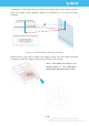
Communication interface
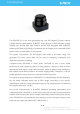
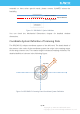
The RPLIDAR S1 uses separate 5V DC power for powering the range scanner core
and the motor system. And the standard RPLIDAR S1 uses SH1.0-6P female
receptacle and interface lead as communication interface. Detailed interface
definition is shown in the following figure:
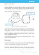
Figure 2-5 RPLIDAR S1 Female Receptacle Definition
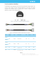
Figure 2-6 RPLIDAR S1 Interface Lead Schematic Diagram
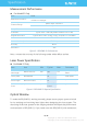
Color
Signal
Name
Type
Description
Min
Typical
Max
Brown
VCC
Power
Total Power
4.8V
5V
5.5V
Purple
Orange
GND
Power
GND
0V
0V
0V
Yellow
Green
RX
Input
Serial port input of the
scanner core
0V
3.3V
3.5V
Blue
TX
Output
Serial port output of
the scanner core
0V
3.3V
3.5V