2021-02-25 rev.2.2 www.slamtec.com Shanghai Slamtec.Co.
Contents CONTENTS ................................................................................................................................................... 1 OVERVIEW ................................................................................................................................................... 3 SDK AND DEMO PROGRAM .............................................................................................................................. 3 PROTOCOL BASICS ...................
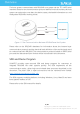
Overview The host system communicates with RPLIDAR core system via the TTL UART serial interface. Based on the communication protocol defined in this document, the host system can retrieve the scan data, the device status, the health information etc. and manipulate RPLIDAR’s working mode.
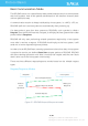
Protocol Basics Basic Communication Mode The RPLIDAR uses a non-textual binary data packet based protocol to communicate with host systems. And all the packets transmitted on the interface channel share uniform packet formats. A communication session is always initialized by a host system, i.e. a MCU, a PC, etc. RPLIDAR itself won’t send any data out automatically after powering up. If a data packet is sent from host systems to RPLIDARs, such a packet is called a Request.
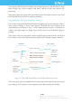
Host system should prevent sending extra request packets if the RPLIDAR is busy with handing the current request and hasn’t replied to the host system yet. Otherwise, these extra request packets will be discarded by the RPLIDAR’s protocol stack and the RPLIDAR will not have any chance to handle it. Single Request-Multiple Response Modes This mode is used when the RPLIAR is asked to perform the scan operation.
responses mode, the RPLIDAR will continue to handle the request which has interrupted it. The request packets sent by the host system during the multiple responses mode will be cached by the RPLIDAR’s protocol stack. After leaving the multiple responses mode, RPLIDAR will handle the cached request. Single Request-No Response For requests like STOP, RESET Core, RPLIDAR uses the single request – no response mode since there is no need to reply to the host system.
A fixed 0xA5 byte is used for each request packet, RPLIDAR uses this byte as the identification of a new request packet. An 8bit (1byte) command field must follow the start flag byte. If the current request carries extra payload data, an 8bit (1byte) payload size field is required to be transmitted after sending the command field and then follows the payload data. After the payload data has been transmitted, an 8bit (1byte) checksum field calculated from the previous sent data should be transmitted.
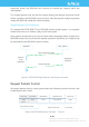
2 … Figure 2-5 Response Packets Sent during a Single Request-Single Response Mode … 2 … Figure 2-6 Response Packets Sent during a Single Request-Multiple Response Mode The format of response descriptors is depicted in the following figure.
A response descriptor uses fixed two bytes’ pattern 0xA5 0x5A for the host system to identify the start of a response descriptor. The 30bit Data Response Length field records the size of a single incoming data response packet in bytes. (All the incoming data response packets within a request/response session should have the same format and length). The 2bits Send Mode field describes the request/response mode of the current session.
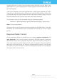
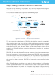
Working State and Mechanism Major Working States and Transition Conditions RPLIDAR has the following 4 major states: Idle, Scanning, Request Processing and the Protection Stop state. The translation conditions are depicted in the following figure: Up Figure 3-1 RPLIDAR’s Major Status Translation The Idle state is the default state of RPLIDAR which will be entered automatically after powering up or reset.
status. But the host system cannot ask the RPLIDAR to perform scan operations unless the host system send a Reset request to reboot the RPLIDAR core system. Scanning Status RPLIDAR always checks the motor rotation status when working in the scanning state. Only when the motor rotation speed becomes stable, RPLIDAR will start taking distance measurement and sending out the result data to the host system.
Request and Response Data Scan Mode and Measurement Frequency A new concept called ‘scan mode’ is introduced since firmware version 1.24. RPLIDAR’s following performance may differ in different scan modes: Measurement frequency Max measurement distance Sensitivity of detection Environment light elimination Different model of RPLIDAR support different set of scan modes. Each of them is optimized for specified work environment.
A new command GET_LIDAR_CONF has been added to help host system to enumerate all scan modes supported by a LIDAR device, as well as the performance parameters of each scan mode. This command can also be used to get “Typical Scan Mode” of a LIDAR, which is the recommend work mode for particular LIDAR model by Slamtec. To avoid problems, SLAMTEC highly recommends users manipulate work modes of an RPLIDAR via the RPLIDAR Public SDKs. Requests Overview All the available requests are listed in the below table.
STOP Request Request Packet: A5 25 RPLIDAR will exit the current scanning state once it receives the Stop (0x25) Request sent by a host system. The laser diode and the measurement system will be disabled and the Idle state will be entered. This request will be ignored when RPLIDAR is in the Idle or Protection Stop state. Since RPLIDAR won’t send response packet for this request, host systems should wait for at least 1 millisecond (ms) before sending another request.
A5 25 A5 … Figure 4-2 The Timing Sequence of a STOP Request RPLIDAR Core Reset(RESET) Request Request Packet: A5 40 Host systems can make RPLIDAR core to reset (reboot) itself by sending this request. A reset operation will make RPLIDAR revert to a similar state as it has just been powered up. This request is useful when RPLIDAR has entered the Protection Stop state. After a core reset, RPLIDAR will return to the idle state which will accept the start scan request again.
Request Packet: A5 20 Response Descriptor: A5 5A Response Mode: 05 Multiple 00 40 00 81 Data Response Length: 5 bytes RPLIDAR, except for the RPLIDAR that is in the Protection Stop State, will enter the scanning state once it receives this request from a host system. Each measurement sample result will be sent out using an individual data response packet. If the RPLIDAR has been in scanning state already, it will stop the current measurement sampling and start a new round of scanning.
RPLIDAR encapsulates each measurement sample into a data response packet with the format showed in the above figure and send the packet out.
θ [0,360) Interface Lead Figure 4-7 Angle and Distance Value Geometric Definition for RPLIDAR A2 series A5 20 A5 … S=1* … A5 5A 05 00 00 40 … 81 Figure 4-8 The Communication Status after Host System Sending a SCAN Request * S of the first scan point of each scan frame are set to 1, otherwise 0. Express Scan(EXPRESS_SCAN) Request and Response Notice: This command have two different versions: legacy version and extended version. The legacy version is reserved for back-compatibility.
legacy version. Please use extended version for scan modes sample more than 4000 times per second and max distance of which exceeds 16m. RPLIDAR Public SDK has been updated to hide the complexity and variety of the protocol. It selects scan mode automatically according to user’s requirement, and is back-compatible to RPLIDARs with firmware prior to 1.24.
RPLIDAR will enter the measurement sampling mode once it receives the express scan(EXPRESS_SCAN) request. Different from the scan(SCAN) request, this request will make RPLIDAR work at the sampling rate as high as it can be. For LIDARs support sampling more than 4000 times per second, the host system should use GET_LIDAR_CONF command to get “Typical Scan Mode”, and use this command to make LIDAR work under its best performance and output measurement sample data accordingly.
Figure 4-10 Field Definition of RPLIDAR Express Scan Data Request Packet 21 / 50 Copyright (c) 2009-2013 RoboPeak Team Copyright (c) 2013-2019 Shanghai Slamtec Co., Ltd.
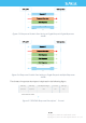
Format of the data response packets (Legacy Version): RPLIDAR uses the following data response packet structure for responding the legacy version of EXPRESS_SCAN requests.
The descriptions of every field within the above packet are listed in the following table: ) Figure 4-12 Field Definition of RPLIDAR Express Scan Data Response Packet 2 Calculation of this check sum should exclude both sync bytes. 23 / 50 Copyright (c) 2009-2013 RoboPeak Team Copyright (c) 2013-2019 Shanghai Slamtec Co., Ltd.
The following table describes the filed definition of the Cabin data. 𝑑𝜃 𝑑𝜃 Figure 4-13 Field Definition of RPLIDAR Express Scan Cabin Data Response Packet The following figure describes the communication status after the host system sending out the express scan request.
Format of the data response packets (Extended Version): RPLIDAR may also respond in following response packet format according to amount of measurements and the link bandwidth. The actual data packet format could also be fetched via GET_LIDAR_CONF command.
) Figure 4-16 Field Definition of RPLIDAR Express Scan Data Response Ultra Capsuled Packet Following table defines fields in ultra cabin data structure: Figure 4-17 Field Definition of RPLIDAR Express Scan Ultra Cabin Data Response Packet Ultra cabin uses a SLAMTEC-patented (CN 108306649 A) compression technology to encode measurements. The `major` field is a 12bit value encoded in a variable scale format. The `predict1` and `predict2` fields are 10bit predict value.
to the source of our public SDK or related patent for technical details. Using opensourced SDK is preferred, comparing to implement decoder on your own.
Format of the data response packets (Dense Version): RPLIDAR may respond in following response packet format according to amount of measurements and the link bandwidth. The actual data packet format could also be fetched via GET_LIDAR_CONF command.
) Figure 4-20 Field Definition of RPLIDAR Express Scan Data Response Dense Capsuled Packet The filed definition of the Cabin data was defined as the following table. Figure 4-21 Field Definition of RPLIDAR Express Scan Dense Cabin Data Response Packet After receiving the dense express scan request, the communication status between RPLIDAR and host system was illustrated in the following chart. 29 / 50 Copyright (c) 2009-2013 RoboPeak Team Copyright (c) 2013-2019 Shanghai Slamtec Co., Ltd.
A5 82 05 A5 … … S=0 S=1 … … ° A5 5A 54 00 00 40 85 Figure 4-22 The Communication Status Sending Out the Dense Capsuled Express Scan Request Data Processing of the Express Scan Data (Capsuled Express Scans) By compressing the redundant data, the data response packet used in express scan mode makes it possible to send the 4khz sampling data via the original 115200bps bandwidth communication link. For this reason, the host system needs extra data recovery logic to get valid measurement data.
Figure 4-23 The Abstract Description for the Response Data Packet of Express Scan Request The above figure indicates the data response packet format of RPLIDAR in the express scan mode. For convenience, after RPLIDAR receives the express scan request and enter express scan mode, the first sent data response packet is denoted as 𝑃 , the second 𝑃 and the ith 𝑃 .
Data Processing of the Express Scan Data (Dense Capsuled Express Scans) When working in this express scan mode, every sampling distance value is stored in the cabin structural body. The distance value is matched with the actual distance measured in this sampling, and the corresponding angle data can be calculated out with the start_angle_q6 in this request.
Force Scan(FORCE_SCAN) Request and Response Request Packet: A5 21 Response Descriptor: A5 5A Response Mode: 05 Multiple 00 00 40 81 Data Response Length: 5 bytes A force scan (FORCE_SCAN) request forces RPLIDAR to start measurement sampling and send out the results immediately once it receives this request. This request is useful for device debugging.
Get Device Info (GET_INFO) Request and Response Request Packet: A5 50 Response Descriptor: A5 5A 14 00 Single Response Mode: 00 00 04 Data Response Length: 20 bytes RPLIDAR will send out its device information (e.g. serial number, firmware/hardware version) to the host system once it receives this request.
Figure 4-26 Field Definition of Device Info Data Response Packet A5 A5 5A 50 14 A5 00 00 00 … 04 Figure 4-27 The Timing Sequence of a GET_INFO Request 35 / 50 Copyright (c) 2009-2013 RoboPeak Team Copyright (c) 2013-2019 Shanghai Slamtec Co., Ltd.
Get Device Health Status (GET_HEALTH) Request and Response Request Packet: A5 52 Response Descriptor: A5 5A 3 Single Response Mode: 00 00 00 06 Data Response Length: 3 bytes A host system can send the GET_HEALTH request to query RPLIDAR’s health state. If the RPLIDAR has entered the Protection Stop state caused by hardware failure, the related error code of the failure will be sent out.
When a host system detects RPLIDAR has entered the Protection Stop state, it can set a RESET request to let RPLIDAR core system reboot to escape the Protection Stop state. However, if RPLIDAR enters the Protection Stop state for several times, this may be a sign of some unrecoverable damage has occurred in RPLIDAR.
The following table describes the filed definition of the above packet. Figure 4-31 Field Definition of Sample Rate Data Response Packet Device configuration query command (GET_LIDAR_CONF) Request Packet: A5 84 S Response Descriptor: A5 5A S Response Mode: Single Request Data 00 00 C 00 20 Data Response Length: Variable Use this command to fetch characters of RPLIDAR. Use type and payload to specify the configuration entry to query.
Fields of above packet format are defined below: Figure 4-33 Definition of Get LIDAR Conf Request Fields 39 / 50 Copyright (c) 2009-2013 RoboPeak Team Copyright (c) 2013-2019 Shanghai Slamtec Co., Ltd.
Format of data response packets: 0 32 Byte Offset: type +0 0 8 payload[0] +4 … 0 8 n+4 payload[n] Figure 4-34 Format of a Get LIDAR Conf Response Packet Fields of above packet format are defined below: Figure 4-35 Definition of Device Configuration Get Command Response Packet Fundamental Data Type Definitions This command uses following fundamental data types or their combination as payload. All data are stored in little-endian byte order.
Figure 4-36 Fundamental Data Types and Definition Available configuration entries Figure 4-37 Supported Configuration Entries RPLIDAR_CONF_SCAN_MODE_COUNT (0x70) Configuration Entry RPLIDAR returns the amount of scan modes supported when receives this command. RPLIDAR supports scan mode ids from 0 to (scan_mode_count – 1). 41 / 50 Copyright (c) 2009-2013 RoboPeak Team Copyright (c) 2013-2019 Shanghai Slamtec Co., Ltd.
For instance, device returning 2 according to this query means that the device support 2 work modes, whose ids are 0, 1. The host system may use the work mode id and other configuration type to get specific characters of the work mode. RPLIDAR_CONF_SCAN_MODE_US_PER_SAMPLE (0x71) Configuration Entry Get sample duration of the scan mode, whose id is specified by the payload of request. The return value is a 32bit unsigned int in Q8 fixed point format.
RPLIDAR_CONF_SCAN_MODE_TYPICAL (0x7C) Configuration Entry Get typical scan mode id of LIDAR. RPLIDAR_CONF_SCAN_MODE_NAME (0x7F) Configuration Entry Get the name of scan mode, whose id is specified by the payload of request. The return value is a string of a user-friendly name for this scan mode. 43 / 50 Copyright (c) 2009-2013 RoboPeak Team Copyright (c) 2013-2019 Shanghai Slamtec Co., Ltd.
Device motor speed control command (MOTOR_SPEED_CTRL)4 A5 Request Packet: A8 02 Rpm C A host system can send this command to control the real-time motor speed of RPLIDAR. And RPLIDAR will be enter the idle state only if have received the command with Rpm = 0. Format of the Data Request Packets: 0 16 Byte Offset: +0 Rpm Figure 4-38 Format of a MOTOR_SPEED_CTRL Request Packet 4 Only RPLIDAR S1 serials support this command at present.
Application Notes Typical work flow of retrieving scanning data from an RPLIDAR It is recommended that a host system always follows the below sequence to enable RPLIDA’s scanning operation and retrieve the scanning data. Before sending a SCAN request, the host system should send a GET_HEALTH request in advance to query the RPLIDAR’s health status. In case RPLIDAR is in the Protection Stop state, the host system can send a RESET request to try to escape the Protection Stop state.
Calculate RPLIDAR Scanning Speed In most cases, there is no need for a host system to care about the actual RPLIDAR scanning speed. RPLIDAR ensures the precision of the measurement results using its build-in self-adaptive motor rotation speed detector. If an RPLIDAR is required to have a fixed scanning speed, the host system can control the motor speed using a PWM driver and based on the speed feedback provided by the algorithm described in this section.
∆T. The interval time represents how long the RPLIDAR has spent to perform a 360o scan. So the actual scan speed can be calculated using the following equation: RPM = 1 ∗ 60 ∆𝑇 The calculated value can be used as a feedback to control the motor speed. 47 / 50 Copyright (c) 2009-2013 RoboPeak Team Copyright (c) 2013-2019 Shanghai Slamtec Co., Ltd.
Revision History 48 / 50 Copyright (c) 2009-2013 RoboPeak Team Copyright (c) 2013-2019 Shanghai Slamtec Co., Ltd.
Appendix Image and Table Index FIGURE 1-1 THE COMMUNICATION BETWEEN RPLIDAR AND HOST SYSTEM ..................................................... 3 FIGURE 2-1 RPLIDAR REQUEST/RESPONSE MODES ............................................................................................ 4 FIGURE 2-2 RPLIDAR SINGLE REQUEST - MULTIPLE RESPONSE MODE .............................................................. 5 FIGURE 2-3 RPLIDAR SINGLE REQUEST-NO RESPONSE MODE ....................................................
FIGURE 4-25 FORMAT OF A DEVICE INFO DATA RESPONSE PACKET................................................................... 34 FIGURE 4-26 FIELD DEFINITION OF DEVICE INFO DATA RESPONSE PACKET ....................................................... 35 FIGURE 4-27 THE TIMING SEQUENCE OF A GET_INFO REQUEST ...................................................................... 35 FIGURE 4-28 FORMAT OF A DEVICE HEALTH DATA RESPONSE PACKET..............................................................