
Development Kit - User Manual

12 / 16
Copyright (c) 2009-2017 RoboPeak Team
Copyright (c) 2013-2017 Shanghai Slamtec Co., Ltd.
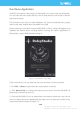
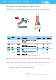
Figure 3-3 RPLIDAR A3 Pins Reference Design
Pin Definition for the USB Adapter
The USB adapter is also using XH2.54-5P specification socket, and it can be
connected with RPLIDAR A3 directly. The pin definition is the same as the RPLIDAR
A3.
USB-DC power cord instruction
The developer kit provides USB-DC power cord for the user to connect additional
power to the USB adapter for additional power supply. For the output voltage and
current requirements of the power supply, please refer to the datasheet of the
corresponding lidar model.
Configure RPLIDAR A3 Scan Frequency
The motor speed control signal MOTOCTL can be configured directly via the USB
adapter of RPLIDAR A3. Therefore, the RPLIDAR A3’s scan frequency can be
modified by invoking the related functions in the SDK to configure the motor
speed.
Without the USB adapter, users can also control the speed by setting the PWM
duty cycle of MOTOCTL. Please note that the PWM frequency is 20kHz. For more
detailed parameter and index, please refer to the datasheet.
Please refer to the RPLIDAR protocol and application note for more information
and the SDK for the sample code on RPLIDAR scan frequency.
V5.0
GND
TX
RX
MOTOCTL
Power
(5V DC)
UART
PWM Generator
MCU/DSP
RPLIDAR