2021-04-02 rev.1.3 Model:A3M1 www.slamtec.com Shanghai Slamtec.Co.
Contents CONTENTS ................................................................................................................................................... 1 OVERVIEW ................................................................................................................................................... 3 ITEMS IN THE DEVELOPMENT KIT ....................................................................................................................... 3 RPLIDAR A3 .......................
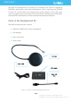
Overview RPLIDAR A3 development kit includes the matched tools used for evaluating RPLIDAR’s performance and initial development. After connecting the RPLIDAR A3 with PC via USB cable and connecting the power adapter to the USB cable, users can observe the cloud map of the environment scanning point collected by the RPLIDAR in RoboStudio and start development based on the SDK.
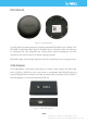
RPLIDAR A3 Figure 1-2 The RPLIDAR The RPLIDAR A3 development kit contains standard RPLIDAR A3 unit (A3M1). The RPLIDAR is embedded with logic IO drivable motor controller which can be used to configure the scan frequency by tuning motor speed. Developers can also choose to turn off the motor for power saving purpose. RPLIDAR usage and interface definition will be introduced in the coming sections. USB Adapter The USB adapter comes with a dial switch.
Connection and Usage Connection RPLIDAR A3 can be easily connected to PC according to the following steps. 1) Connect RPLIDAR A3 with the USB adapter. Figure 2-1 Connect RPLIDAR A3 and USB Adapter 2) Connect the USB adapter to your PC via the Micro-USB cable. If the PC is on, after connecting the USB cable to your PC and connecting the power adapter to the USB cable, the indicator light of the USB will light up but the RPLIDAR will not start scanning.
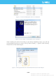
Figure 2-3 Choose USB Adapter Driver for Installation Figure 2-4 Start Page of USB Adapter Driver Installation After Installing the driver according to the above installation steps, you will see corresponding serial port name in the [Control Panel] -> [Device and Printers]. Please refer to the below figure. Figure 2-5 Recognized Serial Port Name Matched with the USB Adapter 6 / 16 Copyright (c) 2009-2017 RoboPeak Team Copyright (c) 2013-2017 Shanghai Slamtec Co., Ltd.
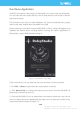
Run Demo Application SLAMTEC provides a Lidars plugin in RoboStudio for users in test and evaluation. You can view the scan result directly in the UI and save the scan result to files for further processing. This GUI demo can only run under Windows. For Linux and MacOS users, please refer to the other simple demo provided in the SDK. Please make sure you have connected RPLIDAR to PC by using USB adapter and installed the device driver correctly before running the demo application in RoboStudio.
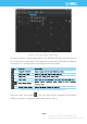
Figure 2-7 The Lidar Plugin in RoboStudio The serial number, version and model of the RPLIDAR A3 will show next with its icon in the lidar control panel. The supported commands of RPLIDAR are showed in the tool bar. The descriptions are listed in the bellow table. Figure 2-8 The Supported Commands of RPLIDAR in RoboStudio Press the Start Scan button ,the scan data will be displayed as below(by default, the motor rotating speed should be about 10Hz.
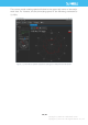
Figure 2-9 The Scan Outline by RPLIDAR in RoboStudio Right click in the major working area to choose a range so as to zoom in or out the view. The scan frequency is also showed in the above interface. Troubleshooting When the scan core or the laser power works abnormally, the scan core will enter protection mode. This state can be retrieved via SDK API. If such scenario happened, please send restart command to reset the scan core.
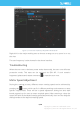
The current actual rotating speed will show in the upper left corner of the major work area. For instance, the actual rotating speed in the following screenshot is 11.92Hz. Figure 2-10 The Motor Speed Adjustment Dialogue of RPLIDAR in RoboStudio 10 / 16 Copyright (c) 2009-2017 RoboPeak Team Copyright (c) 2013-2017 Shanghai Slamtec Co., Ltd.
SDK Introduction and Usage RPLIDAR A3 Pin Definition and Specification RPLIDAR A3 is using XH2.54-5P specification plug. Please use it with socket that meet the specification of XH2.54-5P. The detailed pin definition is shown as below: Red Figure 3-1 RPLIDAR A3 Pins Figure 3-2 RPLIDAR Pin Definition and Specification RPLIDAR A3 uses the one 5V DC power supply for powering the scan motor and the scan core at the same time. No extra power is required.
RPLIDAR V5.0 Power(5V DC) GND TX UART RX MOTOCTL PWM Generator MCU/DSP Figure 3-3 RPLIDAR A3 Pins Reference Design Pin Definition for the USB Adapter The USB adapter is also using XH2.54-5P specification socket, and it can be connected with RPLIDAR A3 directly. The pin definition is the same as the RPLIDAR A3. USB-DC power cord instruction The developer kit provides USB-DC power cord for the user to connect additional power to the USB adapter for additional power supply.
SDK Usage SLAMTEC provides RPLIDAR SDK support on both Windows and Linux platform. And users can embed the SDK source code to other operational system or embedded system quickly. Please refer to the SDK document for more information. 13 / 16 Copyright (c) 2009-2017 RoboPeak Team Copyright (c) 2013-2017 Shanghai Slamtec Co., Ltd.
Operation Recommendation Pre-Heating for Best Performance The scan core will be heating when start working. We recommend pre-heating RPLIDAR (Start the scan mode and the scan motor is rotating) for more than 2 minutes to get the best measurement accuracy. Ambient Temperature RPLIDAR’s measurement resolution is sensitive to the ambient temperature. Improper use may even damage the sensor. Please avoid using RPLIDAR in extreme high temperature (>40 degree) and too low temperature (<-10 degree).
Revision History 15 / 16 Copyright (c) 2009-2017 RoboPeak Team Copyright (c) 2013-2017 Shanghai Slamtec Co., Ltd.
Appendix Image and Table Index FIGURE 1-1 ITEMS IN THE RPLIDAR DEVELOPMENT KIT..................................................................................................... 3 FIGURE 1-2 THE RPLIDAR .......................................................................................................................................................... 4 FIGURE 1-3 RPLIDAR ADAPTER ...........................................................................................................................