
Data Sheet


13 / 18
Copyright (c) 2009-2013 RoboPeak Team
Copyright (c) 2013-2017 Shanghai Slamtec Co., Ltd.
Scanner Motor Control
The RPLIDAR A3M1 is embedded with a motor driver which has speed tuning
feature. Users can control the start, the stop and the rotating speed for the motor
via MOTOCTL in the interface. MOTOCTL can be supplied using PWM signal with
special frequency and duty cycle, and in this mode, the rotating speed is decided
by the duty cycle of the input MOTOCTL PWM Signal.
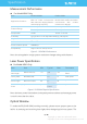
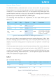
The following table describes the requirement for the input PWM signal of
MOTOCTL:
Figure 2-9 RPLIDA Specification for PWM Signal of MOTOCTL
Note: the typical value is tested when the scanner rotating frequency is 10Hz. With
the same rotating speed, the PWM duty cycle of every RILIDAR A3M1 may vary
slightly. If a precise rotating speed is required, users can perform a closed-loop
control.
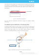
If the host system only need to control the start and stop of the motor, please use
the direct current signal in high level and low level to drive MOTOCTL. Under this
condition, when the MOTOCTL is the low level signal, the RPLIDAR A3M1 will stop
rotating and scanning; when the MOTOCTL is the high level signal, the RPLIDAR
A3M1 will rotated at the highest speed.
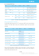
MISC
For Model A3M1 Only
Figure 2-10 RPLIDAR MISC Specification
Item
Unit
Min
Typical
Max
Comments
High level
voltage
V
3.0V
3.3V
5V
-
PWM
frequency
Hz
24,500
25,000
25,500
Square Signal
Duty cycle
range
-
0%
60%*
100%
Typical value is the duty
cycle of high pulse width
when the scanner
frequency is at10Hz
Item
Unit
Min
Typical
Max
Comments
Weight
Gram (g)
TBD
190
TBD
Temperature range
Degree Celsius (
o
C)
0
20
45