
Data Sheet

12 / 18
Copyright (c) 2009-2013 RoboPeak Team
Copyright (c) 2013-2017 Shanghai Slamtec Co., Ltd.
For Model A3M1 Only
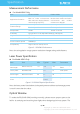
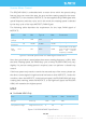
Figure 2-7 RPLIDAR Power Supply Specification
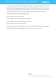
Data communication interface
The RPLIDAR A3M1 takes the 3.3V-TTL serial port (UART) as the communication
interface. The table below shows the transmission speed and the protocol
standard.
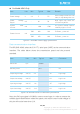
Figure 2-8 RPLIDAR Serial Port Interface Specifications
Note: the RX input signal of A3M1is current control type. In order to ensure the
reliable signal identification inside the system, the actual control node voltage of
this pin will not be lower than 1.6v.
Item
Unit
Min
Typical
Max
Remark
Power Voltage
V
4.9
5
5.5
If the voltage exceeds the max
value, it may damage the core
Power Voltage
Ripple
mV
-
20
50
High ripple may cause the
core working failure.
System Start
Current
mA
-
1200
1500
The system startup requires
relatively higher current.
Power Current
mA
TBD
200
220
5V Power,power off
TBD
450
600
5V Power,power on
Item
Unit
Min
Typical
Max
Comments
Band rate
bps
-
256000
-
-
Working mode
-
-
8N1
-
8n1
Output high voltage
Volt (V)
2.9
-
3.5
Logic High
Output low voltage
Volt (V)
-
-
0.4
Logic Low
Input high voltage
Volt (V)
1.6*
-
3.5
Logic High
Input low voltage
Volt (V)
-0.3
-
0.4
Logic Low