
Data Sheet

11 / 18
Copyright (c) 2009-2013 RoboPeak Team
Copyright (c) 2013-2017 Shanghai Slamtec Co., Ltd.
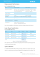
Communication interface
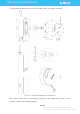
The RPLIDAR A3M1 uses separate 5V DC power for powering the range scanner
core and the motor system. And the standard RPLIDAR A3M1 uses XH2.54-5P
male socket. Detailed interface definition is shown in the following figure:
Figure 2-5 RPLIDAR Power Interface Definition
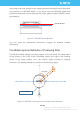
Figure 2-6 RPLIDAR External Interface Signal Definition
Power Supply Interface
RPLIDAR A3M1 takes the only external power to power the range scanner core
and the motor system which make the core rotate. To make the RPLIDAR A3M1
work normally, the host system needs to ensure the output of the power and meet
its requirements of the power supply ripple.
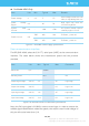
Color
Signal
Name
Type
Description
Min
Typical
Max
Red
VCC
Power
Total Power
4.9V
5V
5.5V
Yellow
TX
Output
Serial port output of
the scanner core
0V
3.3V
3.5V
Green
RX
Input
Serial port input of the
scanner core
0V
3.3V
3.5V
Black
GND
Power
GND
0V
0V
0V
Blue
MOTOCTL
Input
Scan motor /PWM
Control Signal (active
high, internal pull
down)
0V
3.3V
5V
Red
XH2.54-5P
VCC
TX
RX
GND
MOTOCTL