RPLIDAR A3 2018-01-24 rev.1.0 Low Cost 360 Degree Laser Range Scanner Introduction and Datasheet Model: A3M1 OPTMAG 16K www.slamtec.com Shanghai Slamtec.Co.
Contents CONTENTS ................................................................................................................................................... 1 INTRODUCTION ......................................................................................................................................... 3 SYSTEM CONNECTION ........................................................................................................................................ 4 MECHANISM ........................
Introduction The RPLIDAR A3M1 is the next generation low cost 360 degree 2D laser scanner (LIDAR) solution developed by SLAMTEC. It can take up to 16000 samples of laser ranging per second with high rotation speed. And equipped with SLAMTEC patented OPTMAG technology, it breakouts the life limitation of traditional LIDAR system so as to work stably for a long time. The system can perform 2D 360-degree scan within a 25-meter range.
requirements. With the 10Hz scanning frequency, the sampling rate is 16kHz and the angular resolution is 0.225°. Due to the improvements in SLAMTEC hardware operating performance and related algorithm, RPLIDAR A3M1 works well in all kinds of indoor environment and outdoor environment with direct sunlight. Meanwhile, before leaving the factory, every RPLIDAR A3M1 has passed the strict testing to ensure the laser output power meet the eye-safety standard of IEC-60825 Class 1.
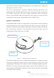
The detailed specification about power and communication interface can be found in the following sections. Mechanism The RPLIDAR A3M1 is based on laser triangulation ranging principle and adopts the high-speed vision acquisition and processing hardware developed by SLAMTEC. The system ranges more than 16000 times per second.
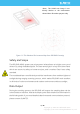
*Note : The LIDAR scan image is not directly relative to the environment showed here. Illustrative purpose only. Figure 1-3 The Obtained Environment Map from RPLIDAR Scanning Safety and Scope The RPLIDAR A3M1 system uses a low power infrared laser as its light source, and drives it by using modulated pulse. The laser emits light in a very short time frame which can ensure its safety to human and pet, and it reaches Class I laser safety standard.
Data Type Unit Description Distance mm Current measured distance value between the rotating core of the RPLIDAR and the sampling point Heading degree Current heading angle of the measurement Start Flag (Bool) Flag of a new scan Checksum The Checksum of RPLIDAR return data Figure 1-4 The RPLIDAR Sample Point Data Information … (dሾn − 1ሿ, θሾn − 1ሿ) (dሾnሿ, θሾnሿ) (dሾ0ሿ, θሾ0ሿ) (dሾ1ሿ, θሾ1ሿ) … Start Flag A new scan Figure 1-5 The RPLIDAR Sample Point Data Frames The RPLIDAR outputs sampling
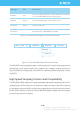
Application Scenarios The RPLIDAR can be used in the following application scenarios: General robot navigation and localization Environment scanning and 3D re-modeling Service robot or industrial robot working for long hours Home service /cleaning robot navigation and localization General simultaneous localization and mapping (SLAM) Smart toy’s localization and obstacle avoidance 8 / 18 Copyright (c) 2009-2013 RoboPeak Team Copyright (c) 2013-2017 Shanghai Slamtec Co., Ltd.
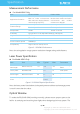
Specification Measurement Performance For Model A3M1 Only Item Enhanced Mode Outdoor Mode Application Scenarios Extreme performance Ideal for indoor environments with maximum ranging distance and sampling frequency. Extreme reliability Ideal for both outdoor and indoor environments with reliable resistance to daylight.
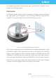
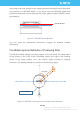
obscuring of the host system for the ranging window will impact the performance and resolution of RPLIDAR A3M1. If you need cover the RPLIDAR A3M1 with translucent materials or have other special needs, please contact SLAMTEC about the feasibility. Optical Window Figure 2-3 RPLIDAR Optical Window You can check the Mechanical Dimensions chapter for detailed window dimensions. Coordinate System Definition of Scanning Data The RPLIDAR A3M1 adopts coordinate system of the left hand.
Communication interface The RPLIDAR A3M1 uses separate 5V DC power for powering the range scanner core and the motor system. And the standard RPLIDAR A3M1 uses XH2.54-5P male socket. Detailed interface definition is shown in the following figure: Red XH2.54-5P MOTOCTL GND RX TX VCC Figure 2-5 RPLIDAR Power Interface Definition Color Signal Name Type Description Min Typical Max Red VCC Power Total Power 4.9V 5V 5.5V Yellow TX Output Serial port output of 0V the scanner core 3.3V 3.
For Model A3M1 Only Item Unit Min Typical Max Remark Power Voltage V 4.9 5 5.5 If the voltage exceeds the max value, it may damage the core Power Ripple mV - 20 50 High ripple may cause the core working failure. mA - 1200 1500 The system startup requires relatively higher current.
Scanner Motor Control The RPLIDAR A3M1 is embedded with a motor driver which has speed tuning feature. Users can control the start, the stop and the rotating speed for the motor via MOTOCTL in the interface. MOTOCTL can be supplied using PWM signal with special frequency and duty cycle, and in this mode, the rotating speed is decided by the duty cycle of the input MOTOCTL PWM Signal.
Self-protection and Status Detection To ensure the laser of RPLIDAR always working in the safety range (<3mW) and avoid any other damage caused by device, the RPLIDAR comes with laser power detection and sensor healthy check feature. It will shut down the laser and stop working automatically when any of the following errors has been detected.
SDK and Support To facilitate the usage of RPLIDAR A3 in the product development and speed up the development cycle for users, SLAMTEC has provided the Lidars plugin in RoboStudio for testing and debugging as well as the SDK available under Windows, x86 Linux and Arm Linux. Please contact SLAMTEC for detail information. Figure 4-1 the Lidars Plugin in RoboStudio 15 / 18 Copyright (c) 2009-2013 RoboPeak Team Copyright (c) 2013-2017 Shanghai Slamtec Co., Ltd.
Mechanical Dimensions The mechanical dimensions of the RPLIDAR A3M1 are shown as below: Figure 5-1 RPLIDAR Mechanical Dimensions Note: the 4 M3 screws in the bottom should be no longer than 4mm, or the internal module would be damaged. 16 / 18 Copyright (c) 2009-2013 RoboPeak Team Copyright (c) 2013-2017 Shanghai Slamtec Co., Ltd.
Revision history Date Version Description 2018-01-24 1.0 Initial version for A3M1 17 / 18 Copyright (c) 2009-2013 RoboPeak Team Copyright (c) 2013-2017 Shanghai Slamtec Co., Ltd.
Appendix Image and Table Index FIGURE 1-1 RPLIDAR SYSTEM COMPOSITION ..................................................................................................... 4 FIGURE 1-2 THE RPLIDAR WORKING SCHEMATIC ............................................................................................... 5 FIGURE 1-3 THE OBTAINED ENVIRONMENT MAP FROM RPLIDAR SCANNING ................................................... 6 FIGURE 1-4 THE RPLIDAR SAMPLE POINT DATA INFORMATION ...............................