RPLIDAR A2 Low Cost 360 Degree Laser Range Scanner Development Kit User Manual Model: A2M4 2016-04-06 rev.01 Shanghai Slam tec Co., Ltd. www.slamtec.
Contents CONTENTS ................................................................................................................................................... 1 1. OVERVIEW ........................................................................................................................................... 3 ITEMS IN THE DEVELOPMENT KIT ....................................................................................................................... 3 RPLIDAR A2 ...........................
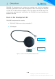
1. Overview RPLIDAR A2 development kit includes the matched tools used for evaluating RPLIDAR’s performance and initial development. After connecting the RPLIDAR A2 with PC via USB cable and adapter, Users can observe the cloud map of the environment scanning point collected by the RPLIDAR and start development based on the SDK.
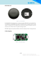
RPLIDAR A2 Figure 1-2 The RPLIDAR The RPLIDAR A2 development kit contains standard RPLIDAR A2 unit (A2M4-R1). The RPLIDAR is embedded with logic IO drivable motor controller which can be used to configure the scan frequency by tuning motor speed. Developers can also choose to turn off the motor for power saving purpose. RPLIDAR usage and interface definition will be introduced in the coming sections.
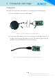
2. Connection and Usage Connection RPLIDAR A2 can be easily connected to PC according to the following steps. 1) Connect RPLIDAR A2 with the USB adapter. Figure 2-1 Connect RPLIDAR A2 and USB Adapter 2) Connect the USB adapter to your PC via the Micro-USB cable. If the PC is on, after connecting the USB cable to your PC, the indicator light of the USB will light up but the RPLIDAR will not start scanning.
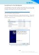
Install Driver for the USB Adapter The USB adapter converts UART to USB by using CP2102 chip. You need to install the device driver for the chip. The driver can be found in the provided SDK package or downloaded from Silicon Labs’ official website: http://www.silabs.com/products/interface/usbtouart/Pages/usb-to-uart-bridge.
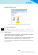
After Installing the driver according to the above installation steps, you will see corresponding serial port name in the [Control Panel] -> [Device and Printers]. Please refer to the below figure. Figure 2-5 Recognized Serial Port Name Matched with the USB Adapter Run Demo Application Frame_grabber is a GUI demo application provided by SLAMTEC. You can view the scan result directly in the UI and save the scan result to files for further processing.
Figure 2-6 Choose Serial Port Name Matched with the USB Adapter If the connection is ok, you shall see the UI like this: Figure 2-7 The Start of Demo Application The firmware/hardware version and serial number of the RPLIDAR will show in the title line of the GUI. The supported commands of RPLIDAR are showed in the tool bar. The descriptions are listed in the bellow table. 8 / 15 Copyright (c) 2009-2013 RoboPeak Team Copyright (c) 2013-2016 Shanghai Slamtec Co., Ltd.
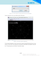
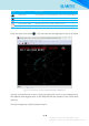
Button Function Description Start Scan Scan data will be displayed after scan core starting work Stop Scan Scan core enter power save mode Save Scan Data Save current scan data to the local file Restart RPLIDAR Adjust Motor Speed Restart scan core to clear internal errors Adjust the motor speed as required Figure 2-8 The Supported Commands in Demo Application Press the Start Scan button ,the scan data will be displayed in the UI as below: Figure 2-9 The Scan Outline in RPLIDAR Demo Application
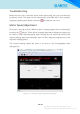
Troubleshooting When the scan core or the laser power works abnormally, the scan core will enter protection mode. This state can be retrieved by using SDK API. If such scenario happened, please send restart command to reset the scan core. Motor Speed Adjustment During the running process, different motor rotating speed can be achieved by pressing the button. There will be a speed adjustment dialog box popped up for users to enter required speed.
3. SDK Introduction and Usage RPLIDAR A2 Pin Definition and Specification RPLIDAR A2 is using XH2.54-5P specification plug. Please use it with socket that meet the specification of XH2.54-5P. The detailed pin definition is shown as below: Red XH2.
RPLIDAR V5.0 Power(5V DC) GND TX UART RX MOTOCTL PWM Generator MCU/DSP Figure 3-3 RPLIDAR A2 Pins Reference Design Pin Definition for the USB Adapter The USB adapter is also using XH2.54-5P specification socket, and it can be connected with RPLIDAR A2 directly. The pin definition is the same as the RPLIDAR A2. Configure RPLIDAR A2 Scan Frequency The motor speed control signal MOTOCTL can be configured directly via the USB adapter of RPLIDAR A2.
4. Operation Recommendation Pre-Heating for Best Performance The scan core will be heating when start working. We recommend pre-heating RPLIDAR (Start the scan mode and the scan motor is rotating) for more than 2 minutes to get the best measurement accuracy. Ambient Temperature RPLIDAR’s measurement resolution is sensitive to the ambient temperature. Improper use may even damage the sensor. Please avoid using RPLIDAR in extreme high temperature (>40 degree) and too low temperature (<-10 degree).
5. Revision History Date Version Description 2016-04-06 0.1(A2M4) Initial 14 / 15 Copyright (c) 2009-2013 RoboPeak Team Copyright (c) 2013-2016 Shanghai Slamtec Co., Ltd.
Appendix Image and Table Index FIGURE 1-1 ITEMS IN THE RPLIDAR DEVELOPMENT KIT..................................................................................................... 3 FIGURE 1-2 THE RPLIDAR .......................................................................................................................................................... 4 FIGURE 1-3 RPLIDAR ADAPTER ...........................................................................................................................