
User Guide


13 / 19
Copyright (c) 2009-2013 RoboPeak Team
Copyright (c) 2013-2016 Shanghai Slamtec Co., Ltd.
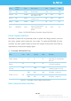
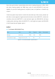
The RPLIDAR A2 takes the 3.3V-TTL serial port (UART) as the communication
interface. The table below shows the transmission speed and the protocol
standard.
Figure 2-8 RPLIDAR Serial Port Interface Specifications
Note: the RX input signal of A2M5/A2M6 is current control type. In
order to ensure the reliable signal identification inside the system, the
actual control node voltage of this pin will not be lower than 1.6v.
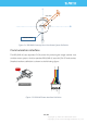
Scanner Motor Control
The RPLIDAR A2 is embedded with a motor driver which has speed tuning feature.
Users can control the start, the stop and the rotating speed for the motor via
MOTOCTL in the interface. MOTOCTL can be supplied using PWM signal with
special frequency and duty cycle, and in this mode, the rotating speed is decided
by the duty cycle of the input MOTOCTL PWM Signal.
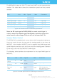
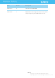
The following table describes the requirement for the input PWM signal of
MOTOCTL:
Figure 2-9 RPLIDA Specification for PWM Signal of MOTOCTL
Item
Unit
Min
Typical
Max
Comments
Band rate
bps
-
115200
-
-
Working mode
-
-
8N1
-
8n1
Output high voltage
Volt (V)
2.9
-
3.5
Logic High
Output low voltage
Volt (V)
-
-
0.4
Logic Low
Input high voltage
Volt (V)
1.6*
-
3.5
Logic High
Input low voltage
Volt (V)
-0.3
-
0.4
Logic Low
Item
Unit
Min
Typical
Max
Comments
High level
voltage
V
3.0V
3.3V
5V
-
PWM
frequency
Hz
24,500
25,000
25,500
Square Signal
Duty cycle
range
-
0%
60%*
100%
Typical value is the duty
cycle of high pulse
width when the scanner
frequency is at10hz