
User Guide


12 / 19
Copyright (c) 2009-2013 RoboPeak Team
Copyright (c) 2013-2016 Shanghai Slamtec Co., Ltd.
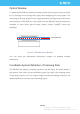
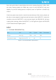
Figure 2-6 RPLIDAR External Interface Signal Definition
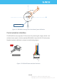
Power Supply Interface
RPLIDAR A2 takes the only external power to power the range scanner core and
the motor system which make the core rotate. To make the RPLIDAR A2 work
normally, the host system needs to ensure the output of the power and meet its
requirements of the power supply ripple.
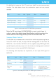
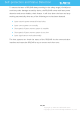
For Model A2M5/A2M6 Only
Figure 2-7 RPLIDAR Power Supply Specification
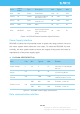
Data communication interface
Color
Signal
Name
Type
Description
Min
Typical
Max
Red
VCC
Power
Total Power
4.9V
5V
5.5V
Yellow
TX
Output
Serial port output of
the scanner core
0V
3.3V
3.5V
Green
RX
Input
Serial port input of the
scanner core
0V
3.3V
3.5V
Black
GND
Power
GND
0V
0V
0V
Blue
MOTOCTL
Input
Scan motor /PWM
Control Signal (active
high, internal pull
down)
0V
3.3V
5V
Item
Unit
Min
Typical
Max
Remark
Power Voltage
V
4.9
5
5.5
If the voltage exceeds the
max value, it may damage
the core
Power Voltage
Ripple
mV
-
20
50
High ripple may cause the
core working failure.
System Start
Current
mA
-
1200
1500
The system startup requires
relatively higher current.
Power Current
mA
TBD
200
220
5V Power,power off
TBD
450
600
5V Power,power on