RPLIDAR A2 Low Cost 360 Degree Laser Range Scanner 2018-03-23 rev.1.1 Introduction and Datasheet Model: A2M5 A2M6 OPTMAG 4K-8K www.slamtec.com Shanghai Slamtec.Co.
Contents CONTENTS ................................................................................................................................................... 1 INTRODUCTION ......................................................................................................................................... 3 SYSTEM CONNECTION ........................................................................................................................................ 4 MECHANISM ........................
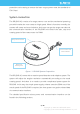
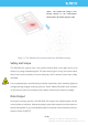
Introduction The RPLIDAR A2 is the next generation low cost 360 degree 2D laser scanner (LIDAR) solution developed by SLAMTEC. It can take up to 8000 samples of laser ranging per second with high rotation speed. And equipped with SLAMTEC patented OPTMAG technology, it breakouts the life limitation of traditional LIDAR system so as to work stably for a long time. RPLIDAR A2M5/A2M6 is the enhanced version of 2D laser range scanner(LIDAR). The system can perform 2D 360-degree scan within a 18-meter range.
passed the strict testing to ensure the laser output power meet the standards of FDA Class I. System connection The RPLIDAR A2 consists of a range scanner core and the mechanical powering part which makes the core rotate at a high speed. When it functions normally, the scanner will rotate and scan clockwise. And users can get the range scan data via the communication interface of the RPLIDAR and control the start, stop and rotating speed of the rotate motor via PWM.
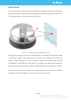
Mechanism The RPLIDAR A2 is based on laser triangulation ranging principle and adopts the high-speed vision acquisition and processing hardware developed by SLAMTEC. The system ranges up to 8000 times per second. 𝒅 Figure 1-2 The RPLIDAR Working Schematic During every ranging process, the RPLIDAR emits modulated infrared laser signal and the laser signal is then reflected by the object to be detected.
*Note : The LIDAR scan image is not directly relative to the environment showed here. Illustrative purpose only. Figure 1-3 The Obtained Environment Map from RPLIDAR Scanning Safety and Scope The RPLIDAR A2 system uses a low power infrared laser as its light source, and drives it by using modulated pulse. The laser emits light in a very short time frame which can ensure its safety to human and pets, and it reaches Class I laser safety standard.
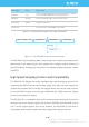
Data Type Unit Description Distance mm Current measured distance value between the rotating core of the RPLIDAR and the sampling point Heading degree Current heading angle of the measurement Start Flag (Bool) Flag of a new scan Checksum The Checksum of RPLIDAR return data Figure 1-4 The RPLIDAR Sample Point Data Information … (dሾn − 1ሿ, θሾn − 1ሿ) (dሾnሿ, θሾnሿ) (dሾ0ሿ, θሾ0ሿ) (dሾ1ሿ, θሾ1ሿ) … Start Flag A new scan Figure 1-5 The RPLIDAR Sample Point Data Frames The RPLIDAR outputs sampling
Application Scenarios The RPLIDAR can be used in the following application scenarios: o General robot navigation and localization o Environment scanning and 3D re-modeling o Service robot or industrial robot working for long hours o Home service /cleaning robot navigation and localization o General simultaneous localization and mapping (SLAM) o Smart toy’s localization and obstacle avoidance 8 / 19 Copyright (c) 2009-2013 RoboPeak Team Copyright (c) 2013-2016 Shanghai Slamtec Co., Ltd.
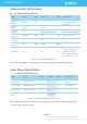
Specification Measurement Performance For Model A2M5/A2M6 Only Item Distance Range Angular Range Distance Resolution Angular Resolution Sample Duration Sample Frequency Scan Rate Unit Min Typical Max Comments Meter(m) 0.2 - 18 Based om white objects with 70% reflectivity Degree - 0-360 - - mm - <0.5 <1% of the distance - <1.5 meters All distance range* Degree 0.45 0.9 1.35 10Hz scan rate Millisecond(ms ) - 0.
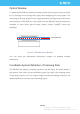
Optical Window To make the RPLIDAR A2 working normally, please ensure proper space to be left for its emitting and receiving laser lights when designing the host system. The obscuring of the host system for the ranging window will impact the performance and resolution of RPLIDAR A2. If you need cover the RPLIDAR A2 with translucent materials or have other special needs, please contact SLAMTEC about the feasibility.
θ ሾ0,360) Interface Lead Figure 2-4 RPLIDAR Scanning Data Coordinate System Definition Communication interface The RPLIDAR A2 uses separate 5V DC power for powering the range scanner core and the motor system. And the standard RPLIDAR A2 uses XH2.54-5P male socket. Detailed interface definition is shown in the following figure: Red XH2.54-5P MOTOCTL GND RX TX VCC Figure 2-5 RPLIDAR Power Interface Definition 11 / 19 Copyright (c) 2009-2013 RoboPeak Team Copyright (c) 2013-2016 Shanghai Slamtec Co.
Color Signal Name Type Description Min Typical Max Red VCC Power Total Power 4.9V 5V 5.5V Yellow TX Output 0V 3.3V 3.5V Green RX Input 0V 3.3V 3.5V Black GND Power GND 0V 0V 0V Input Scan motor /PWM Control Signal (active high, internal pull down) 0V 3.
The RPLIDAR A2 takes the 3.3V-TTL serial port (UART) as the communication interface. The table below shows the transmission speed and the protocol standard. Item Unit Min Typical Max Comments Band rate bps - 115200 - - Working mode - - 8N1 - 8n1 Output high voltage Volt (V) 2.9 - 3.5 Logic High Output low voltage Volt (V) - - 0.4 Logic Low Input high voltage Volt (V) 1.6* - 3.5 Logic High Input low voltage Volt (V) -0.3 - 0.
Note: the typical value is tested when the scanner rotating frequency is 10Hz. With the same rotating speed, the PWM duty cycle of every RILIDAR A2 may vary slightly. If a precise rotating speed is required, users can perform a closed-loop control. If the host system only need to control the start and stop of the motor, please use the direct current signal in high level and low level to drive MOTOCTL.
Self-protection and Status Detection To ensure the laser of RPLIDAR always working in the safety range (<3mW) and avoid any other damage caused by device, the RPLIDAR comes with laser power detection and sensor healthy check feature. It will shut down the laser and stop working automatically when any of the following errors has been detected.
SDK and Support SLAMTEC provides debug GUI tool and SDK (available for Windows, x86 Linux and Arm Linux) to speed up the product development for users. Please contact SLAMTEC for detail information. Figure 4-1 The Debugging GUI of RPLIDAR 16 / 19 Copyright (c) 2009-2013 RoboPeak Team Copyright (c) 2013-2016 Shanghai Slamtec Co., Ltd.
Mechanical Dimensions The mechanical dimensions of the RPLIDAR A2 are shown as below: Figure 5-1 RPLIDAR Mechanical Dimensions Note: the 4 * M3 screws in the bottom should be no longer than 4mm, or the internal module would be damaged. 17 / 19 Copyright (c) 2009-2013 RoboPeak Team Copyright (c) 2013-2016 Shanghai Slamtec Co., Ltd.
Revision history Date Version Description 2016-08-12 1.0 Initial Version A2M5/A2M6 2018-03-23 1.1 Updated the version number to 1.1; Updated the scan range from 16m to 18m and the sample frequency from 4000-4100 to 4k -8k. 18 / 19 Copyright (c) 2009-2013 RoboPeak Team Copyright (c) 2013-2016 Shanghai Slamtec Co., Ltd.
Appendix Image and Table Index FIGURE 1-1 RPLIDAR SYSTEM COMPOSITION ..................................................................................................... 4 FIGURE 1-2 THE RPLIDAR WORKING SCHEMATIC ............................................................................................... 5 FIGURE 1-3 THE OBTAINED ENVIRONMENT MAP FROM RPLIDAR SCANNING ................................................... 6 FIGURE 1-4 THE RPLIDAR SAMPLE POINT DATA INFORMATION ...............................