
Data Sheet

9 / 16
Copyright (c) 2009-2013 RoboPeak Team
Copyright (c) 2013-2016 Shanghai Slamtec Co., Ltd.
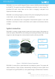
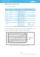
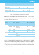
Figure 2-5 RPLIDAR External Interface Signal Definition
Note: the RX input signal of A1M8 is recognized by the current. In order to ensure
the reliable signal identification inside the system, the actual control node voltage
of this pin will not be lower than 1.6v.
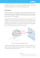
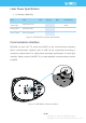
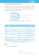
Figure 2-6 RPLIDAR A1 External Interface Specifications
Note: for the motor interface and core interface of batch version, they use the
PH1.25-3P horizontal pitch connector and PH1.25-4P vertical pitch connector
respectively. Please refer to the mechanical dimensions in Chapter 5 for details of
signals and their matched pins. But the RPLIDAR development kit uses the PH2.54-
7P pitch connector. Please refer to
RPLIDAR Development Kit User Manual
for
detailed specifications.
Item
Unit
Min
Typical
Max
Comments
Band rate
bps
-
115200
-
Working mode
-
-
8N1
-
8n1
Output high voltage
Volt (V)
2.9
-
3.5
Logic High
Output low voltage
Volt (V)
-
-
0.4
Logic Low
Input high voltage
Volt (V)
1.6*
-
3.5
Logic High
Input low voltage
Volt (V)
-0.3
-
0.4
Logic Low
Interface
Signal
Name
Type
Description
Min
Typical
Max
Motor
Interface
VMOTO
Power
Power for RPLIDAR A1 Motor
-
5V
9V
MOTOCTL
Input
Enable signal for RPLIDAR A1
Motor/PWM
Control Signal
0V
-
VMOTO
GND
Power
GND for RPLIDAR A1 Motor
-
0V
-
Core
Interface
VCC_5
Power
Power for RPLIDAR A1 Range
Scanner Core
4.9V
5V
5.5V
TX
Output
Serial output for Range Scanner
Core
0V
-
5V
RX
Input
Serial input for Range Scanner
Core
0V
-
5V
GND
Power
GND for RPLIDAR A1 Range
Scanner Core
-
0V
V5.0