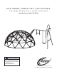
GEO DOME SWING SET ACCESSORY Assembly, Maintenance, and User Manual Skywalker Sports Model # SSGD700 WARNING Read all precautions and instructions in this manual before using this equipment. Save this manual for future reference. Total weight limit 162 lbs.
Model# ID label is located at the bottom base of the Geo Dome Swing Set Accessory. Size of the whole product: L5660xW3650xH2700mm Model SSGD700 GEO DOME - Accessories Made in China Skywalker Holdings, LLC PO Box 547, Brigham City, UT, 84302 USA www.Skywalkertrampolines.com Factory address: Qingda Industrial Park Chengyang Qingdao Shandong China (Model # ID label location) CONTENTS Before You Begin .............................................3 Important Precautions ..................................
BEFORE YOU BEGIN Thank you for selecting a Skywalker Sports Geo Dome Swing Set Accessory. The Geo Dome Accessory kit can provide many years of backyard fun. Your Geo Dome comes equipped with warnings and instructions for the assembly, care, maintenance, and use. This information must be read by all Geo Dome Swing set Accessory supervisors and communicated to or read by all users before any person is allowed to use the Geo Dome.
PLAYGROUND SURFACING MATERIALS INFORMATION The following information is from Section 4 of the United States Consumer Product Safety Comission’s (USCPSC) Outdoor Home Playground Safety Handbook for playground surfacing material. X3. SECTION 4 OF THE CONSUMER PRODUCT SAFETY COMMISSION’S OUTDOOR HOME PLAYGROUND SAFETY HANDBOOK X3.
USER INSTRUCTIONS Observing the following statement and warnings reduces the likelihood of serious or fatal injury. 1. The Geo Dome accessory is designed for up to 2 persons and has a 162 lb. total weight limit. 2. On-site adult supervision for children of all ages at all times is required. 3. Instruct children not to walk close to, in front of, behind, or between moving items. Instruct children to keep a safe distance away to keep from being struck by items in play. 4.
GEO DOME SAFETY INFORMATION A Geo Dome is a recreational product. The information on this manual identify important safety precautions. The precautions are not all-inclusive, because a geo dome can be used in ways that this manual cannot cover completely. USING THE GEO DOME SAFELY Adult Supervision of Children Children using the geo dome must be supervised by adults at all times.
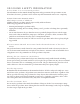
ASSEMBLY PARTS IDENTIFICATION Before beginning assembly, refer to the drawings below to identify all the parts used. The numbers in the circles to the left of each part will be used to help differentiate the parts in the instructions. 1 2 3 Basketball hoop Stand x1 Backboard x1 x1 5 4 Flex Rod With Connector (ĭ6) x2 Flex Rod Thin (ĭ6) x1 7 6 Cross Flex Rod(Thick) (ĭ9.
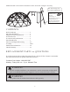
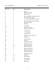
ASSEMBLY Key No. 1 2 3 10 11 20 21 22 23 24 25 27 30 32 Qty. 1 1 1 1 2 2 2 12 10 1 1 1 10 2 PARTS LIST Description Stand Basketball hoop Backboard )OH[ 5RG :LWK &RQQHFWRU ĭ )OH[ 5RG 7KLQ ĭ &URVV )OH[ 5RG 7KLFN ĭ )OH[ 5RG :LWK &OLS (QG ĭ 0 [ PP %ROW 0 1XW Cross Bar Plastic Protector 8SULJKW ³5´ ³/´ ³8´ )UDPH ³8´ )UDPH &RQQHFW WXEH :HOGHG WXEH ³5´ ³/´ 7RS WXEH *\PQ
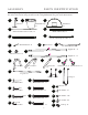
ASSEMBLY PARTS LOCATION DRAWING Tools provided # S4 S5 S6 3 17 14 2 1 15 13 15 16 13 18 16 10 12 19 12 9
ASSEMBLY 1 Use the parts to left for this step. Using the pictured tool, pull the spring of the basketball hoop(2) through large hole of the stand(1) and hook to the smaller hole below. Now attach the basketball hoop to the hoop stand using the M6x62mm bolt and M6 nut. 8 2 M6x62mm x1 9 x1 x1 M6 x1 # 1. 2. 4 3 x1 x1 Using the the parts pictured to left, slide the flex rod with connector (4) through the tabs on the top of the backboard(3) (make sure the backside is facing you.
ASSEMBLY 3. 4 x1 5 x1 4 Using the parts pictured on the left, attach flex rod thin(5) to the ends of the flex rod with connector(4) placed in step 2. Then bend both rods (4 & 5)into the bottom tabs on the backboard (3).
ASSEMBLY Attach the tabs around the poles. 4. 3 5. 6 Backside Using the Cross Flex Rod(Thick)(6) pictured to the left, slide through the bottom of the backboard, and through the side of the hoop stand(1) from step 1 to connect the two together.
ASSEMBLY 6. 7 Using the flex rod with clip end (7)to the left, slide the through the back tabs of the backboard.
ASSEMBLY 7. x1 10 x2 11 M6 x2 9 20 x2 M6x40mm 29 M6 x2 R 8. 12 x1 Using the parts pictured to the left, attach the cross bar from step 7 to the upright (12). L x1 21 x2 31 M8x35mm Using the parts pictured to the left, connect the plastic protector (11) to the cross bar (10).
ASSEMBLY 9. 22 13 x1 Using the parts pictured to the left, attach the "U" frame 1(13) to the poles from step 8 to complete the swing set A-frame. x4 M8x60mm x8 31 Note: Tighten all the bolts. M8 28 x4 10. 14 L x1 x2 M8x60mm 31 R R L ! x16 x1 x1 28 L x8 22 16 15 ! 15 M8 x8 Using the parts pictured to the left connect the shorter A-frame pieces together.
ASSEMBLY Using the parts pictured to the left, attach the "U"-frame 2 (14) to the geo dome at the two 10 hole plates. (This is the plates with the addition holes from step 5 of the geo dome assembly) Then insert the End cap(32) into the middle hole on the Plate. 11. 14 23 30 M8x15mm M8 x10 32 x10 x2 R L L L 12.
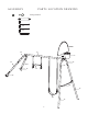
ASSEMBLY 13. 26 31 x4 28 x2 Using the parts pictured to the left, attach the basketball game to the swing set frame. Note: This will also attach the top tube to the A-frame piece. M8x108mm 27 M8x68mm 14. 18 M8 Using the parts pictured to the left, now attach the swing and gymnast bar. Note: The bolts and washers are pre-installed. Please loosen the bolts and washers first. 19 x1 x1 The assembly of your Geo Dome and Swing Set Acessory are now complete.
MAINTENANCE INFORMATION This product was manufactured using quality materials and crafted to provide you and your family with many years of enjoyment and exercise. Proper maintenance care will help to prolong the life and reduce the possibility of injury. The following guidelines should be followed. 1. Tighten all hardware at the beginning of each play season. 2. Lubricate all metallic moving parts per manufacturer’s instructions. 3. Check all protective coverings on bolts, pipes, edges, and corners.
LIMITED WARRANTY Skywalker Holdings, LLC warranties its products to be free from defects in material and workmanship under normal use and service conditions. The steel frame is warranted for one (1) year after the date of purchase. All other parts are warranted for ninety (90) days after the date of purchase. Wind or weather damage is not warranted. All warranty coverage extends only to the original retail purchaser from the date of purchase.