SECTION CONTENTS Section Subject Section 1 Safety Practices . . . . . . . . . . . . . . . . . . . . . . . . . . . . . . . . . . . . . . . . . . . . . . . . . . . . . . . 1.1 1.2 1.3 1.4 1.5 1.6 1.7 1.8 Page 1.1 Introduction . . . . . . . . . . . . . . . . . . . . . . . . . . . . . . . . . . . . . . . . . . . . . . . . . . . . . . . . . . Owners/Operators Manual . . . . . . . . . . . . . . . . . . . . . . . . . . . . . . . . . . . . . . . . . . . . . . Training Mechanics as Operators . . . . . . . . . .
Section Subject Page Section 5 Axles, Drive Shafts, Wheels and Tires . . . . . . . . . . . . . . . . . . . . . . . . . . . . . . . . . . . . . . 5.1 5.2 5.3 5.4 5.5 5.1 Axle, Drive Shaft and Wheel Component Terminology . . . . . . . . . . . . . . . . . . . . . . . . . General Information . . . . . . . . . . . . . . . . . . . . . . . . . . . . . . . . . . . . . . . . . . . . . . . . . . . . Axle Assemblies . . . . . . . . . . . . . . . . . . . . . . . . . . . . . . . . . . . . . . . . . . . . . . . . .
Section Subject Section 9 Electrical System . . . . . . . . . . . . . . . . . . . . . . . . . . . . . . . . . . . . . . . . . . . . . . . . . . . . . . 9.1 9.2 9.3 9.4 9.5 9.6 9.7 9.8 9.9 9.10 9.11 9.12 9.13 9.14 9.15 Electrical Component Terminology . . . . . . . . . . . . . . . . . . . . . . . . . . . . . . . . . . . . . . . . Service Warnings . . . . . . . . . . . . . . . . . . . . . . . . . . . . . . . . . . . . . . . . . . . . . . . . . . . . . Specifications . . . . . . . . . . . . . . . . . . . .
Section Subject Page This Page Intentionally Left Blank iv Model 6042 Legacy Origin 7/02
Section 1 Safety Practices Contents PARAGRAPH 1.1 1.2 1.3 1.4 1.5 1.6 1.7 1.8 Model 6042 Legacy TITLE Introduction . . . . . . . . . . . . . . . . . . . . . . . . . . . . . . . . . . . . . . . . . . . . . . . . . . . . . . . Owners/Operators Manual . . . . . . . . . . . . . . . . . . . . . . . . . . . . . . . . . . . . . . . . . . . Training Mechanics as Operators . . . . . . . . . . . . . . . . . . . . . . . . . . . . . . . . . . . . . Safety Information. . . . . . . . . . . . . . . . . . . . . . . .
Safety Practices 1.1 INTRODUCTION OmniQuip Textron Inc. (hereafter, OmniQuip) products meet all applicable industry safety standards. OmniQuip actively promotes safe practices in the use and maintenance of its products through training programs, instructional manuals and the pro-active efforts of all employees involved in engineering, design, manufacture, marketing and service.
Safety Practices 1.3 TRAINING MECHANICS AS OPERATORS Because it is necessary to move the vehicle to service or maintain the vehicle, it is necessary that all mechanics are OSHA trained and certified as operators. A mechanic trained in the proper operation of the vehicle can better determine whether all functions are operating correctly. At the time of original purchase, the purchaser of this vehicle was instructed by the seller on its proper use.
Safety Practices 1.4.2 Hazard Statements Signal words and messages are used in conjunction with the safety alert symbol to create hazard statements. These hazard statements convey important information about safety. 1.5 ACCIDENT PREVENTION TAG USAGE Four types of hazard statements are used in this manual. Each statement indicates the existence and degree of relative risk of the hazard described within the statement that follows the signal word.
Safety Practices 1.6 SAFETY INSTRUCTIONS Following are general safety statements to consider before performing maintenance procedures on a vehicle. Additional statements related to specific tasks and procedures are located throughout this manual and are listed prior to any work instructions to provide safety information before the hazard occurs. For all safety messages, carefully read, understand and follow the instructions before proceeding. 1.6.
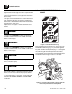
Safety Practices 1.6.3 General Hazards SOLVENTS: Only use approved solvents, and solvents that are known to be safe for use. HOUSEKEEPING: Keep the work area and operator’s cab clean and remove all hazards (debris, oil, tools, etc.). FIRST AID: Immediately clean, dress and report all injuries (cuts, abrasions, burns, etc.), no matter how minor. Know the location of a first-aid kit, and know how to use it.
Safety Practices 1.8 HAZARD/EMERGENCY INFORMATION DECALS If a replacement decal is needed, refer to the owners/ operators manual and parts catalog for the latest parts numbers and ordering information, or, contact OmniQuip Textron Parts Worldwide directly at: Locations of vehicle hazard and other emergency information decals are shown below. As part of routine maintenance, check that ALL hazard and emergency information decals on the vehicle are present and readable. Keep all decals clean.
Safety Practices This Page Intentionally Left Blank 1.
Section 2 General Information and Specifications Contents PARAGRAPH 2.1 2.2 2.3 2.4 2.5 TITLE 6042 Component Terminology . . . . . . . . . . . . . . . . . . . . . . . . . . . . . . . . . . . . . . . . . . Introduction . . . . . . . . . . . . . . . . . . . . . . . . . . . . . . . . . . . . . . . . . . . . . . . . . . . . . . . . . 2.2.1 Service Methods. . . . . . . . . . . . . . . . . . . . . . . . . . . . . . . . . . . . . . . . . . . . . . . . 2.2.2 The Owners/Operators Manual . . . . . . . . . . . .
General Information and Specifications 2.6 Fluids, Lubricants and Capacities . . . . . . . . . . . . . . . . . . . . . . . . . . . . . . . . . . . . . . . 2.6.1 Axles (Differential Housings) . . . . . . . . . . . . . . . . . . . . . . . . . . . . . . . . . . . . . . 2.6.2 Axle Wheel Ends . . . . . . . . . . . . . . . . . . . . . . . . . . . . . . . . . . . . . . . . . . . . . . . 2.6.3 Transmission. . . . . . . . . . . . . . . . . . . . . . . . . . . . . . . . . . . . . . . . . . . . . . . . . . . 2.6.
General Information and Specifications 2.1 6042 COMPONENT TERMINOLOGY To understand the safety, operation and maintenance information presented in this manual, it is necessary that the operator/mechanic be familiar with the names and locations of the major assemblies on this vehicle. The following illustration identifies the components that are referred to throughout this manual.
General Information and Specifications 2.2 2.2.1 INTRODUCTION Service Methods Appropriate service methods and proper repair procedures are essential for safe, reliable operation of this vehicle and the safety of the individual doing the work. This Service Manual provides general direction for accomplishing service and repair work with tested, effective techniques. Following them will assure reliability.
General Information and Specifications The vehicle serial number plate (Fig. 2-1, 1) is located at the front of the vehicle on the frame sway cylinder upright. A warranty registration form must be filled out by the OmniQuip Authorized Service Center (ASC), signed by the purchaser and returned to OmniQuip when the vehicle is sold and/or put into use. Registration activates the warranty period and helps to assure that warranty claims are promptly processed.
General Information and Specifications 2.3 2.3.1 TORQUES 2.3.3 SAE 37° Flare Hydraulic Fittings a. Assembly Procedure Fasteners All fasteners (nuts, bolts, washers, etc.) are equal to SAE Grade 5 (PC8.8) and are plated, unless otherwise specified. Follow these steps when tightening hose ends, tube ends and fitting swivel ends onto fitting male end connections (Refer to Fig. 2-2). 2.3.2 Improper assembly of this type of joint will result in leaking joints.
General Information and Specifications 4. Using a permanent type ink marker, make a mark (Fig. 2-2, 2) on one of the flats on the nut and continue it onto the static fitting or port. 5. Complete the joint by wrench tightening (Fig. 2-2, 3) the nut the number of flats (4) specified in the table for the size and type of fitting. This assembly procedure is referred to as Flats From Finger Tight (FFFT). 6. A less desirable tightening method is nut torque. First follow 1 & 2 above.
General Information and Specifications c. Adjustable (Angle) O-Ring Boss Fittings To O-Ring Boss Ports d. Pipe Fittings to Pipe Ports Improper assembly of this joint will result in a leaking joint. Failure to position the locknut properly will result in damage to the o-ring. Under tightening of the fitting will result in the fitting loosening during normal operation and the joint leaking. Damaging the o-ring during assembly will result in immediate joint leakage. 1.
General Information and Specifications 2.3.4 SAE Flat Face O-Ring Seal Hydraulic Fittings a. Assembly Procedure Improper assembly of this type of joint will result in leaking joints. Under tightening will result in the joint loosening during normal usage. Foreign material on either seal surfaces will cause damage to one or both mating parts when the joint is tightened resulting in a leaking joint. The absences of the fitting o-ring will cause the joint to leak. 1. Inspect both the male (Fig.
General Information and Specifications c. Adjustable (Angle) O-Ring Boss Fittings To O-Ring Boss Ports Improper assembly of this joint will result in a leaking joint. Failure to position the locknut properly will result in damage to the o-ring. Under tightening of the fitting will result in the fitting loosening during normal operation and the joint leaking. Damaging the o-ring during assembly will result in immediate joint leakage. 1.
General Information and Specifications This Page Intentionally Left Blank Model 6042 Legacy Origin 7/02 2.
General Information and Specifications 2.4 METRIC CONVERSION FACTORS VOLUME Teaspoons (tsp) 2.4.1 Approximate American to Metric Conversions When this is known Multiply by To find TORQUE (moment of force) Pound/feet (lb-ft) 1.356 Newton meters (Nm) Pound/inches (lb-in) 0.113 Newton meters (Nm) Horsepower (hp) Tablespoons (Tbsp) 15 3 745.7 Milliliters (ml) Fluid ounces (fl oz) 30 Milliliters (ml) Cups (c) 0.24 Liters Pints (pt) 0.47 Liters Quarts (qt) 0.95 Liters 3.8 Liters 0.
General Information and Specifications 2.4.
General Information and Specifications 2.5 SPECIFICATIONS 2.5.1 Vehicle Dimensions (With Standard 12-ply 13.00-24 Tires) Description (Fig.
General Information and Specifications U I M V J N 0.0 Q P C S R F 24.0" K T L O D A B E H G MA10,0670 Figure 2-6 Vehicle Dimensions with Standard Tires Model 6042 Legacy Origin 7/02 2.
General Information and Specifications 2.5.2 Vehicle Weights Curb Weight w/48" Carriage (Open Cab) 23,520 lb (10.668 kg) Curb Weight w/48" Carriage (Enclosed Cab) 23,720 lb (10.759 kg) Operating Load 6,000 lb (2721 kg) Working Weight (Machine working weight is figured with 72" carriage, two 48" pallet forks, 25%-full fuel tank, and standard bias ply tires [no hydrofill]): Open Cab: Front Axle 9,030 lb (4.096 kg) Rear Axle 14,710 lb (6.672 kg) Total (Open Cab) 23,740 lb (10.
General Information and Specifications 2.5.3 Attachment Weights Std 48" Carriage with Shaft 456 lb (205 kg) Std 60" Carriage with Shaft 526 lb (239 kg) Std 72" Carriage with Shaft 677 lb (307 kg) 48" Side Tilt Carriage with Shaft and Cylinder 687 lb (312 kg) 60" Side Tilt Carriage with Shaft and Cylinder 752 lb (341 kg) 72" Swing Carriage with Shaft and Cylinder 900 lb (408 kg) Bucket, 1.
General Information and Specifications 2.5.5 Hydraulic Cylinder Performance Specifications Note: Vehicle with no load, engine at full throttle, hydraulic oil above 130° F (54° C) minimum, engine at operating temperature. Function Approximate Times, in Seconds Boom Extend Less than 19 seconds Boom Retract Less than 19 seconds Boom Lift Retracted Less than 17 seconds Boom Lower Retracted Less than 13 seconds Attachment Tilt - UP 6.
General Information and Specifications 2.5.6 Electrical System Battery: Type, Rating 12V DC, Negative (-) Ground, Maintenance-Free Quantity 1 Reserve Capacity 1,000 Cold Cranking Amps @ 0° F (-18° C) Group/Series C31XH Alternator 12V, 65 Amps Fuses - Standard Blade Style: 7.
General Information and Specifications 2.5.7 Engine Performance Specifications Note: Engine manufacturer's maximum “high idle” setting is lockwired and sealed. DO NOT disturb this setting. Engine Make/Model Cummins Turbo/4BT3.
General Information and Specifications 2.5.8 Fluid and Lubricant Capacities Engine Crankcase Oil: Capacity with Filter Change 11.0 qt (10,4 liters) Filter Capacity 1.0 qt (0,9 liters) Oil Type SAE 15W40 Diesel Engine Oil (Refer to Section 2.6.6, “Engine.”) Fuel Tank: Total Capacity 37.0 gal (140 liters) Usable Capacity 35.7 gal (135,1 liters) Type of Fuel Above 32° F (0° C) Standard No. 2 Diesel. (Refer to Section 2.6.6, “Engine.
General Information and Specifications 2.5.
General Information and Specifications 2.5.12 Tamper Proofing WARNING: A tamper-proof means is in place on the following adjustable components prior to machine shipment. This can either be tamper-proof paint, or a steel tamper-proof cap. DO NOT attempt to defeat, bypass or alter any tamper-proof device. DO NOT exceed the total rated capacity of the specific pair of forks being used.
General Information and Specifications 2.6.2 Axle Wheel Ends a. Axle Wheel-End Lubricants In general, use a Universal Tractor Fluid that meets the following specifications: Products known to meet these requirements include: • JOHN DEERE: JDM J20C (HY-GARD) • FORD/NEW HOLLAND: ESN-M2C134-D (Hydraulic Oil 134) Nominal viscosity at 104° F (40° C)....................... 55 cSt • MASSEY-FERGUSON: M-1141 (PERMANTRAN III) Minimum viscosity at 212° F (10° C) .................... 9.
General Information and Specifications 2.6.5 Hydraulic System a. Hydraulic Fluids The hydraulic system is factory-filled with ISO Grade 46 anti-wear hydraulic oil. When filling the hydraulic system, use an anti-wear hydraulic oil meeting ISO Grade 46 with -40° F (-40° C) pour point/ASTM viscosity SUS 215 at 100° F (38° C), or a 10W motor oil that meets the requirements of U.S. ordinance specification MIL-L-2104C.
General Information and Specifications 2.6.7 Drive Shaft Splines IMPORTANT: DO NOT disassemble any of the drive shafts (refer to Section 5, “Axles, Drive Shafts, Wheels and Tires” of this manual for information covering drive shafts and U-joints). To help ensure optimum performance, the drive shaft assemblies are specially balanced as a unit at the factory. When servicing any flange yoke, slip yoke or drive shaft tube, order a complete assembly.
General Information and Specifications 2.6.10 Paint 2.6.11 Unless otherwise specified, paint components as indicated in the following sections. a. Orange Paint Durable, premium Sky Trak orange paint is available in both a convenient 16-ounce (480 ml) spray can for touchups, and in a production-size, one gallon (3,8 liters) container for extensive repainting. Consult the appropriate parts manual for the applicable part number and ordering information.
General Information and Specifications 2.8 REPLACEMENT ALWAYS use the correct tool when removing or replacing any part or performing any service. Some procedures may require the use of specialized tools. If needed, many of these tools can be obtained through Snap-on® tool distributors. Contact: Snap-on Incorporated P.O. Box 1410 Kenosha, WI 53141-1410 USA Phone: (262)-656-5200 Internet: http://www.snapon.com Snap-on® is a registered trademark of Snap-on Technologies, Inc.
General Information and Specifications 2.10.3 Bearing Installation 2.12 1. Always install bearings carefully to help avoid damaging their delicate surfaces. 2. Install bearings using one of the following methods: After Service Startup • PRESS FIT for installation on rotating parts such as shafts and gears Note: Refer to the appropriate Owners/Operators manual for engine cold start procedures. • PUSH FIT into static locations such as reduction gear housings 1.
General Information and Specifications 2.12.3 After Hydraulic Component Service 1. Check the torque of fasteners on replaced components. 2. Check that the hoses and tubes are properly attached, properly positioned and that all fittings are properly tightened. 3. If a hydraulic component failed and contaminated the system: • Drain the hydraulic oil reservoir • Flush the system using clean hydraulic oil • Prime the pump • Clean the hydraulic oil reservoir • Change the hydraulic oil filter 4.
General Information and Specifications 2.12.7 After Tire and Wheel Service 1. Check air pressure. Maintain proper air pressure at all times. • 13.00-24, 12 ply - 70 psi (483 kPa) • 15.50-25, 12 ply - 65 psi (448 kPa) 2. Check wheel nut torque. Torque the wheel nuts to 430-470 lb-ft (583-637 Nm). 2.12.8 After Engine Service Consult the qualified service agent (manufacturer’s representative and/or service manual) for proper procedures before engine startup. 2.12.9 After Boom Service 1.
General Information and Specifications This Page Intentionally Left Blank 2.
Section 3 Boom Contents PARAGRAPH 3.1 3.2 3.3 3.4 3.5 3.6 3.7 Model 6042 Legacy TITLE Boom System Component Terminology . . . . . . . . . . . . . . . . . . . . . . . . . . . . . . . . Boom System . . . . . . . . . . . . . . . . . . . . . . . . . . . . . . . . . . . . . . . . . . . . . . . . . . . . . 3.2.1 Boom System Description. . . . . . . . . . . . . . . . . . . . . . . . . . . . . . . . . . . . . 3.2.2 Boom System Operation . . . . . . . . . . . . . . . . . . . . . . . . . . . . . . . . . . .
Boom 3.1 BOOM SYSTEM COMPONENT TERMINOLOGY To understand the safety, operation and maintenance information presented in this section, it is necessary that the operator/mechanic be familiar with the names and locations of the major assemblies of the boom system. The following illustration identifies the components that are referred to throughout this section.
Boom WARNING: DO NOT service the vehicle without following all safety precautions as outlined in the “Safety Practices” section of this manual. Failure to follow the safety practices may result in death or serious injury. 3.2 3.2.1 BOOM SYSTEM Boom System Description The boom operates via an interchange among the hydraulic and mechanical systems.
Boom 3.3.1 Inner Boom Removal WARNING: Wear protective footwear with reinforced toe caps and slip-resistant soles. Failure to comply can result in foot or other bodily injury from crushing, slipping or falling. 3. Remove the thumbscrew (Fig. 3-2, 1), lockwasher (2) and flat washer (3) holding the rear cover (4) to the rear of the outer boom (5). Lift the rear cover straight up until the capscrew in the top of the cover clears the retaining hole in the top of the outer boom.
Boom 5. Remove the elastic locknut (Fig. 3-4, 1) and shoulder bolt (2) holding the two yoke plates (3) to the mount at the front of the outer boom. Retain the shoulder bolt and discard the elastic locknut. 2 3 6. Inspect the yoke plates (Fig. 3-4, 3) for wear or distortion. If any wear or distortion is detected, both plates must be replaced. If no wear is detected, the plates can remain assembled to the extend chain clevis.
Boom 14. Place an Accident Prevention Tag on both the ignition key switch and the steering wheel, stating that the vehicle should not be operated. (Refer to Section 1.5, “Accident Prevention Tag Usage.”) 15. Allow the engine, transmission and hydraulic fluid to cool before proceeding. 16. Disconnect the battery negative (-) cable at the battery negative (-) terminal to prevent the engine from starting accidentally.
Boom 2 5 4 1 3 2 6 1 OA0512 MH2840 Figure 3-9 Clamp Support Bracket Inside Inner Boom 22. Pull the free ends of the attachment tilt hoses (Fig. 3-10, 1) and auxiliary hydraulic hoses (2) from inside the inner boom and out the rear of the boom (3). Allow the hoses to hang from the rear of the boom. Figure 3-11 Retract Chain Locknut Note: Record the location of the shoulder bolt (Fig. 3-12, 1) to ensure correct installation. 24. At the rear of the boom, locate the retract chain (Fig.
Boom Note: If replacing the inner boom assembly with a new inner boom, the quick attach assembly and the attachment tilt cylinder should be removed at this time. If the inner boom is not to be replaced, the quick attach assembly and attachment tilt cylinder can remain in place. Proceed to Step 34. 30. Inspect the pin for nicks or surface corrosion. Use fine emery cloth to repair minor nicks or corrosion. If damaged and if it cannot be repaired, the pin must be replaced. 25.
Boom 33. Lower the attachment tilt cylinder (Fig. 3-15, 4) with the hoist and remove from the backside of the gooseneck. Place the attachment tilt cylinder on a clean, level surface. 1 3 2 4 Note: Use a hoist capable of lifting 5,000 lbs (2268 kg) and two slings to remove the inner boom. 34. Place the slings around the inner boom. Pull the inner boom straight out of the intermediate boom. Reposition the slings as needed so the inner boom balances when removed from the intermediate boom.
Boom 3.3.2 Intermediate Boom Removal WARNING: Wear protective footwear with reinforced toe caps and slip-resistant soles. Failure to comply can result in foot or other bodily injury from crushing, slipping or falling. WARNING: 4 NEVER lift a heavy object without the help of at least one assistant or a suitable sling and hoist. Failure to comply can result in death or serious personal injury. 3 2 1. Remove the inner boom as described in Section 3.3.1, “Inner Boom Removal.” 2.
Boom 6. Remove the retract chain sheave pin (Fig. 3-22, 3) from the mount and the retract chain sheave (4). Remove the retract chain sheave from the intermediate boom. 7. Inspect the bushings inside the sheave. Replace the bushings if there are any signs of wear. Inspect the pin for wear or damage. Replace the pin if showing signs of wear. 9. Remove the capscrews (Fig.
Boom 10. Pull the hose reel with hoses out the back of the intermediate boom. Allow the hose reel assembly to slide down the hoses and rest it on the floor. 11. Label and remove the hoses from the hose reel. The center bolt (Fig. 3-25, 1) can remain in place to hold the hose reel and side plates together. a. Remove the 3/8-16 elastic locknut (Fig. 3-25, 2) and 3/8" flat washer (3) from the lower retaining shoulder bolt (4).
Boom 2 2 1 MA2071 Figure 3-28 Wear Pad Wear Indicators 1 2 MA10,0490 3 Figure 3-27 Extend/Retract Cylinder Rod End Pin Note: Use a hoist with a lifting capacity of 5,000 lbs (2268 kg) and two slings to remove the intermediate boom. 18. Place the slings around the intermediate boom. Pull the intermediate boom straight out of the outer boom. Reposition the slings as needed so the intermediate boom balances when removed from the outer boom.
Boom b. Remove the capscrews (Fig. 3-30, 1), lockwashers (2) and flat washers (3) holding the bottom wear pad (4) and spacer (5) to the intermediate boom. Label the wear pad and spacer as “Bottom.” Also note the orientation of the mounting hole offset. Save the capscrews, lockwashers, flat washers, spacer and wear pad inserts (6). 6 4 5 3 2 1 1 2 3 MH1070 5 Figure 3-31 Intermediate Boom Upper Rear Wear Pads 4 6 MH1060 Figure 3-30 Intermediate Boom Rear Wear Pads c. Remove the capscrews (Fig.
Boom 3.3.3 Outer Boom Removal WARNING: Wear protective footwear with reinforced toe caps and slip-resistant soles. Failure to comply can result in foot or other bodily injury from crushing, slipping or falling. 5. At the underside of the outer boom, locate the retract chain locknut (Fig. 3-34, 1). Remove the elastic locknut and the flat washer (2). Save the flat washer and discard the locknut. WARNING: NEVER lift a heavy object without the help of at least one assistant or a suitable sling and hoist.
Boom 7. At the rear left side of the outer boom, label and remove the (outer) auxiliary hose for the female coupler (Fig. 3-35, 1) and the (inner) hose (2) for the male nipple from the tubes on the mounting plate (3). Plug the hose ends and cap tube ends. 11. At the rear right side of the outer boom, label the extend tube (Fig. 3-37, 1) and retract tube (2) Remove the bulkhead nuts (3). Lift the tube out of the bulkhead plate (4) and re-thread the nut onto the end of the tube. 8.
Boom 16. Label the attachment tilt tube assemblies (Fig. 3-38, 2) located under the boom. Remove the stacking bolts (6) holding the tube clamps (7), locking plates (8) and attachment tilt tubes (2) to the underside of the outer boom. Save the stacking bolts, clamps and locking plates. 19. Remove the capscrew (Fig. 3-40, 1) and elastic locknut (2) holding the upper slave cylinder pivot pin (3) to the outer boom. Securely block (4) the slave cylinder (5) in position.
Boom 22. On the right side boom pivot mounting plate, locate the boom sensor (Fig. 3-41, 1). Remove the hex nut (2) on the inside of the mounting plate. Remove the boom sensor from the outside of the plate, re-thread the nut onto the sensor and allow the sensor to rest on top of the frame, next to the mounting plate. The sensor can remain connected to the harness. 1 3 2 2 MA9750 1 Figure 3-42 Lift/Lower Cylinder Pivot Pins 26. Remove the capscrews (Fig.
Boom 27. Use the hoist to remove the outer boom from the frame. Position the outer boom on a hard, flat surface. Block the boom as required to allow removal of the extend/retract cylinder from the underside of the boom. 28. Use a hoist and slings to support the extend/retract cylinder. At the base end of the cylinder, remove a retaining ring (Fig. 3-44, 1) from one side of the cylinder base end pin (2).
Boom 35. If replacing the outer boom assembly, on the left side of the outer boom, remove the locknut (Fig. 3-47, 1), angle indicator (2) and flat washers (3) from the weld stud. Save the angle indicator and all the hardware for reassembly. If not replacing the boom section, the angle indicator can remain in place. WARNING: NEVER weld or drill the boom. The structural integrity of the boom will be impaired if subjected to any repair involving welding or drilling.
Boom 3.3.4 Outer Boom Installation WARNING: Wear protective footwear with reinforced toe caps and slip-resistant soles. Failure to comply can result in foot or other bodily injury from crushing, slipping or falling. 2. Assemble a new angle indicator decal (Fig. 3-50, 1) to the left side of the boom assembly. Place the hole in the decal around the weld stud (2) and line up 0° mark (3) on the decal with the mark (4) made in step 1.
Boom 4. Install new or saved lift/lower cylinder bearings (Fig. 3-52, 1) into the lift/lower cylinder mounts (2) on each side of the boom assembly. Orient the fracture (3) in the outer race of each bearing at the 3 o’clock position. Press the bearings into position until the edge of the outer race (4) of each bearing is flush with the edge of the plate (5). 5. Install new or saved slave cylinder bearings (Fig. 3-52, 6) into the slave cylinder mounts (7) on each side of the boom assembly.
Boom 11. On the end of the boom pivot pin (Fig. 3-56, 1), closest to the capscrew hole, mark the capscrew mounting hole location. Coat the entire pin with anti-seize compound. 12. Insert the pivot pin (Fig. 3-56, 1) from the outside of the boom assembly, making sure the marks for the capscrew mounting hole stay in line with the capscrew mounting holes in the boom mounting hub. If necessary, use a rawhide hammer to install the pivot pin. 1 2 3 MA10,0530 4 13.
Boom 15. Align the rod end of one of the lift/lower cylinders (Fig. 3-57, 1) with the self-aligning bearing on the outer boom assembly. 20. Use a hoist and sling to position the rod end of the slave cylinder (Fig. 3-58, 1) in line with the selfaligning bearing on the outer boom. 16. Coat the entire lift/lower cylinder pivot pin (Fig. 3-57, 2) with anti-seize compound. Insert the pin through the rod end of the cylinder and the self-aligning bearing. If necessary, use a rawhide hammer to install the pin.
Boom 24. Insert the boom sensor (Fig. 3-59, 1) through the hole in the right side mounting plate (2). Install the jam nut (3), saved, onto the boom sensor on the inside of the plate. Adjust the inner and outer jam nuts on the boom sensor until the gap (4) between the sensor and the boom is .12" (3 mm). Torque the inside jam nut to 36 lb-in (4,1 Nm), to hold the boom sensor in position.
Boom 29. Assemble the inside boom extend hose (Fig. 3-61, 1), coming from the frame bulkhead plate, to the boom extend tube (2), mounted to the inside of the mounting plate (3). Remove all twists from the hose, and tighten the end securely to the end of the tube. 34. Position the attachment tilt cylinder retract tube assembly (Fig. 3-62, 4) in the top inside hole on the mounting plate (2).
Boom 39. Place the lower clamp halves (Fig. 3-63, 5) on each side of the auxiliary hydraulic (lower) tubes (6). Loosely secure the lower clamp halves to the stacking bolt with a clamp cover (7), saved, and a 5/16-18 x 1-1/4" capscrew (8), saved. Verify that the tubes sit properly in all three tube clamp positions and the mounting plate. Tighten the capscrews securely to hold the lower tubes in place in all three positions. 40. Fully tighten both auxiliary tube bulkhead nuts (Fig. 3-62, 7 and 9).
Boom 45. Make sure the retract chain has been inspected before installing it in the outer boom. Refer to Section 3.4.1, “Boom Chain Inspection.” 48. At the front of the outer boom, reassemble the lower outside wear pads (Fig. 3-66, 1) and wear pad spacers (2): 46. Inside the rear of the outer boom, slide the threaded clevis end (Fig. 3-65, 1) of the retract chain down the right side of the boom. Guide the threaded part of the clevis out through the hole in the tab (2) on the bottom of the outer boom.
Boom 49. Install the intermediate boom, retract chain and attaching hardware. (Refer to Section 3.3.5, “Intermediate Boom Installation.”) 50. Install the inner boom, extend chain and attaching hardware. (Refer to Section 3.3.6, “Inner Boom Installation.”) 51. Clean up all debris, hydraulic fluid, etc., in, on, near and around the vehicle. WARNING: Avoid prolonged engine operation in closed areas without adequate ventilation.
Boom 3.3.5 Intermediate Boom Installation WARNING: Wear protective footwear with reinforced toe caps and slip-resistant soles. Failure to comply can result in foot or other bodily injury from crushing, slipping or falling. 1 2 5 WARNING: NEVER lift a heavy object without the help of at least one assistant or a suitable sling and hoist. Failure to comply can result in death or serious personal injury.
Boom c. Place the wear pad inserts (Fig. 3-69, 5), saved, into the cavities in the wear pad (6). Be sure the inserts are seated completely in the cavities. d. Install the wear pad (Fig. 3-69, 6) onto the capscrews. Be careful not to push the wear pad inserts out of the wear pads. e. Apply Loctite® 242 threadlocker to the threads of the two 3/8-16 x 1-1/2" capscrews (Fig. 3-69, 7), saved.
Boom Note: Shim ALL upper rear wear pads as needed to maintain a total maximum gap of .06" (1,5 mm) at the rear of the pads and maintain a total minimum gap of .07-.13" (1,8- 3,3 mm) in the vertical direction. 5. Assemble the top wear pads to the top of the intermediate boom. Position the wear pads so the wear pad mounting holes are offset as noted in disassembly: a. Apply Loctite® 242 threadlocker to the threads of the 3/8-16 x 1" capscrews (Fig. 3-71, 1), saved. b. Place the wear pad shims (Fig.
Boom 10. Remove the slings and the hoist from the intermediate boom. 12. Assemble the top wear pads to the inside of the outer boom: 11. Install the side wear pads to the outer boom: a. Slide the intermediate boom over to one side as far as it will go, to allow wear pad installation. b. Place the wear pad inserts (Fig. 3-73, 1), saved, into the cavities of the side wear pads (2), saved. c. Place the shims (3), saved if present, onto the wear pad and align the holes. d.
Boom c. Apply Loctite® 242 threadlocker to the threads of the 3/8-16 x 1-1/2" capscrews (Fig. 3-76, 4), saved. Align the holes and secure in place with the capscrews (4) and 3/8" lockwashers (5), saved. Be careful not to push the wear pad inserts out of the wear pads. 13. Use a hoist and sling to lift the rod end of the extend/ retract cylinder (Fig. 3-75, 1). Align the rod end of the extend/retract cylinder with the mounts (2) at the front of the intermediate boom. 14.
Boom 3.3.6 Inner Boom Installation WARNING: Wear protective footwear with reinforced toe caps and slip-resistant soles. Failure to comply can result in foot or other bodily injury from crushing, slipping or falling. WARNING: NEVER lift a heavy object without the help of at least one assistant or a suitable sling and hoist. Failure to comply can result in death or serious personal injury.
Boom 5. Keep the four hoses in line (left to right) as they come out of the rear of the inner boom. Place a 5/16" lockwasher (Fig. 3-79, 1), saved, and a 5/16" flat washer (2), saved, onto each 5/16-18 x 5" capscrew (3), saved. Insert the capscrews through the hose clamp support bracket (4), saved. Insert the capscrews from the side as shown. 10. Assemble the hose clamp support bracket to the top of the inner boom: 6. Place a 3/4" diameter hose clamp half (Fig. 3-79, 5), saved, onto the capscrews.
Boom 12. Assemble the remaining wear pads to the rear of the inner boom. The upper left wear pad has already been assembled. c. Apply Loctite® 242 threadlocker to the threads of the 3/8-16 x 1-3/4" capscrews (Fig. 3-81, 5), saved. Align the holes and secure the wear pads in place with the capscrews (5) and 3/8" lockwashers (6), saved. Be careful not to push the wear pad inserts out of the wear pads. Note: Shim ALL upper rear wear pads as needed to maintain a total maximum gap of .
Boom c. Apply Loctite® 242 threadlocker to the threads of the 3/8-16 x 3/4" capscrews (Fig. 3-83, 4), saved. Slide the wear pad (2) with shims (3) between the inner boom and the intermediate boom with the offset of each wear pad the same as noted in disassembly. Align the holes and secure in place with the capscrews (4), 3/8" lockwashers (5), saved, and 3/8" flat washers (6), saved. Be careful not to push the wear pad inserts out of the wear pads. d.
Boom c. Torque all wear pad mounting capscrews to 31 ±3 lb-ft (42 ±4 Nm). Note: ALWAYS replace elastic-lined nuts with new elastic-lined nuts to help ensure proper fastening. d. Fill all wear pad cavities with a good grade of lithium-base EP grease. 4 b. Insert the retaining capscrew (Fig. 3-85, 2) back through the plates of the hose reel, inserting the spacers (3) back in position between the plates as the capscrew is inserted.
Boom 22. Tie the strings (positioned inside the outer boom) to the male end of each of the attachment tilt hoses and the auxiliary hydraulic hoses. IMPORTANT: Keep the hoses in the same order as they come off the hose reel. DO NOT allow the hoses to cross. 23. Working from the front of the boom, pull each hose through the boom assembly: a. Pull the right side auxiliary hydraulic hose (Fig. 3-86, 1) through the boom assembly. Pull the hose out of the opening (2) at the bottom of the outer boom. b.
Boom 5 3 1 3 2 7 1 2 4 MH2340 Figure 3-88 Retract Chain 6 2 4 1 8 5 7 3 MA10,0160 28. Place the double extend chain sheave (Fig. 3-89, 1), saved, between the mounts at the front of the intermediate boom. Insert the sheave pin (2), saved, through the mounts and the double sheave. Align the mounting hole in the sheave pin with the threaded hole in the sheave mount and secure in place with the 1/2-13 x 1" capscrew (3), saved, and the 1/2" lockwasher (4), saved. Tighten securely. 29.
Boom 30. Assemble the two extend chains to the outer boom mount if the yoke plates were removed from the extend chains. If the yoke plates were not replaced, proceed to Step 33. 31. Assemble the yoke plates (Fig. 3-90, 1) to the mount on the front of the outer boom. Coat the shoulder bolt (2), saved, with anti-seize compound and insert the shoulder bolt through a yoke plate (1), the mount on the boom and through a second yoke plate (1) on the bottom. Secure in place with a new 1/2-13 elastic locknut (3).
Boom 1 1 2 2 6 ~ 3 4 4 2 3 3 5 5 3 2 MH1720 6 7 MH1730 Figure 3-93 Auxiliary Hydraulic Coupler and Nipple Figure 3-92 Quick Attach 36. If the inner boom has been replaced with a new boom, the auxiliary hydraulic fittings need to be reassembled: a. Assemble the two bulkhead fittings (Fig. 3-93, 1) from the original boom to the bulkhead plate inside the gooseneck. Insert the bulkhead fittings from the top and secure in place with the bulkhead fitting nut (2) on the bottom side.
Boom 37. Use a hoist and slings to position the attachment tilt cylinder (Fig. 3-95, 1) inside the gooseneck (2). Be sure the attachment tilt cylinder is positioned with the tube for the rod end positioned inside the gooseneck. 38. Coat the base end pivot pin (Fig. 3-95, 3), saved, with anti-seize compound. Align the hole in the cylinder base end with the mounting holes in the gooseneck and insert the pivot pin through the gooseneck.
Boom 42. Assemble the right side hose (Fig. 3-97, 3) labeled as “Extend” to the extend port (lower) fitting (4) on the base end of the attachment tilt cylinder. Index the elbow end of the hose to remove any undo tension and tighten the elbow completely to the fitting on the cylinder. 1 2 1 3 3 4 5 2 MA9820 4 Figure 3-98 Rear Cover to Outer Boom MH1740 Figure 3-97 Attachment Tilt Hoses 43. Clean up all debris, hydraulic fluid, etc., in, on, near and around the vehicle. 44.
Boom 3.4 BOOM CHAINS This vehicle uses double extend chains to extend the boom and a single retract chain to retract the boom. The extend and retract chains are constructed of 3/4" pitch links with 6 x 6 leaf lacing. Note: DO NOT attempt to repair a chain. Replace a stretched or damaged chain with a new part. Always replace both the chain and the clevis. It is recommended that when any chain is replaced, that all the chains and clevis’ be replaced at the same time. 3.4.
Boom a. Inspection Guidelines Edge Wear Expose the extend and retract chains (refer to Section 3.4.1, b. “Expose Extend Chain for Inspection,” or Section 3.4.1, c. “Expose Retract Chain for Inspection”) and inspect the chains for the following conditions: Elongation When the original length (Fig. 3-100, 1) of 12" (305 mm) per foot of new chain has elongated from wear to a length (2) of 12-3/8" (313 mm), the chain must be discarded and replaced. (Refer to Section 3.4.
Boom Turning or Protruding Pins Highly loaded chain, operating with inadequate lubrication, can generate abnormal frictional forces between pin and link plates. When chain is allowed to operate in this condition, a pin or series of pins, can begin to twist out of a chain, resulting in failure. Examine the pin head rivets to determine if the “VEE” flats are still in correct alignment (Fig. 3-103, 1). Chain with rotated/displaced heads (2) or abnormal pin protrusion (3) must be replaced immediately.
Boom Other Modes of Failure b. Expose Extend Chain for Inspection • Ultimate Strength Failure - These types of failures are caused by overloads far in excess of the design load. Either fractured plates (Fig. 3-105, 6) or enlarged holes (7) can occur. If either of these failures occurs, the chain must be replaced immediately. (Refer to Section 3.4.5, “Boom Extend and Retract Chains Removal and Replacement.”) Note: The tight joints inspection must be done with the chain disconnected from the boom.
Boom c. Expose Retract Chain for Inspection 4 The retract chain must be removed from the boom in order to be visually inspected. This must be done every 1000 hours or whenever the retract chain is removed from the boom. (If removal of the chain is required refer to Section 3.4.5, “Boom Extend and Retract Chains Removal and Replacement.”) 5 While doing the chain inspection, check all chain clevis ends for distortion or cracking and sheaves for bearing wear or grooving from the chain.
Boom 6. If the chain clevis has a threaded hole on the end (Fig. 3-108, 1), a string or wire can be attached to the retract chain clevis using a threaded eye (2) or a flat washer tack welded to a capscrew (3). The outside diameter of the eye or flat washer must be smaller than the diameter of the threads on the clevis. The string or wire will be used to pull the chain back through the boom during the reassembly.
Boom 11. Measure the chain elongation. Measure across 17 pins (Fig. 3-110, 1), somewhere between the chain sheave and where the chain is laying in the pan or on the tarp. The maximum measurement allowed is 12-3/8" (313 mm). If the measurement is more than 12-3/8" (313 mm), the chain must be replaced. (Refer to Section 3.4.5, “Boom Extend and Retract Chains Removal and Replacement.”) 14. Coat the threads of the threaded clevis (Fig. 3-111, 1) with multi-purpose grease.
Boom If no string or wire was installed to the end of the clevis: 3 18. From the rear of the boom, one person should push the threaded clevis end (Fig. 3-112, 1) of the retract chain (2) under the chain sheave and down between the intermediate boom and the outer boom. Keep the retract chain (2) to the right side of the boom, push the threaded clevis down to the tab (3) at the front underside of the outer boom. 19. The person at the front of the boom should guide the threaded end of the clevis (Fig.
Boom 3.4.2 Chain Lubrication After inspection and before being returned to service, chains must be lubricated with a quality chain lubricant (“LUBRIPLATE” Chain & Cable Fluid, “LPS3” or equivalent). 4. Measure the sag in the top boom extend chains (Fig. 3-115, 1) between the bottom of the extend chains and the top of the intermediate boom at their closest point (2). Acceptable boom chain sag (3) is between 1-1/2" (38 mm) and 2-1/2" (64 mm). The lubricant must penetrate the chain joint to prevent wear.
Boom 3.4.4 Boom Chain Tension Adjustment Note: Always perform Section 3.4.3, Boom Chain Tension Check before adjusting the boom chain tension. 2. Tighten or loosen the two extend chain adjustment locknuts (Fig. 3-118, 1) located at the rear of the boom. Be sure each of the locknuts are adjusted equally so that each extend chain maintains the same tension. Equal chain tension can be checked by the position of the yoke (Fig. 3-116, 2) on the outer boom.
Boom 4. Recheck chain tension. (Refer to Section 3.4.3, “Boom Chain Tension Check.”) 3 2 5. Further chain adjustment can be achieved by loosening all three chain locknuts (Fig. 3-120, 1 and Fig. 3-121, 1) and moving the rear retract chain clevis (Fig. 3-122, 1) from the original mounting hole (2) in the anchor plate to the next hole (3).
Boom 2 If the distance is less than 8-1/2" (216 mm) or greater than 9-1/2" (241 mm): 1. Verify that the retract chain clevis (Fig. 3-126, 1) is not mounted in the last hole (2) in the anchor plate (3). 1 3 2 1 3 4 5 MA9820 MA9450 Figure 3-124 Rear Cover on Outer Boom Figure 3-126 Move the Rear Retract Chain Clevis a.
Boom 3. To increase the separation distance: Loosen the retract chain locknut (Fig. 3-127, 1) on the bottom of the outer boom one or two turns and tighten the two extend chain locknuts (Fig. 3-128, 1) equally the same number of turns. A minimum of 1 full thread on the clevis must protrude beyond the elastic collar of the locknut. 1 4. To decrease the separation distance: Loosen the extend chain locknuts (Fig.
Boom 4. At the rear of the boom, locate the extend chain elastic locknuts (Fig. 3-130, 1). Record the amount of threads extending beyond both the elastic locknuts. These measurements will be the starting point for adjustment of the extend chains after installation. 5. Remove and replace the extend chains one at a time. Remove the right side elastic locknut (Fig. 3-130, 1) and flat washer (2), holding the right side extend chain clevis (3) to the anchor plate (4) on the inner boom (5).
Boom 11. Lay the new extend chain (Fig. 3-133, 1) on top of the outer boom (2) with the threaded clevis (3) toward the front of the boom. 16. Pull the anchor clevis (Fig. 3-135, 1) up around the double chain sheave and position the clevis between the yoke plates (2). 12. Attach the wire (Fig. 3-133, 4) to the threaded clevis (3) of the new extend chain. Loop the wire through the clevis and twist together to form a loop. 17. Coat the hex-socket head capscrew (Fig.
Boom 6. If the chain clevis has a threaded hole on the end (Fig. 3-138, 1), a string or wire can be attached to the retract chain clevis using a threaded eye (2) or a flat washer tack welded to a capscrew (3). The outside diameter of the eye or flat washer must be smaller than the diameter of the threads on the clevis. The string or wire will be used to pull the chain back through the boom during the reassembly.
Boom Note: Record the location of the shoulder bolt (Fig. 3-139, 4) to ensure correct installation. 13. Coat the threads of the threaded clevis (Fig. 3-140, 1) with multi-purpose grease. 9. At the rear of the boom, locate the two retract chain anchor plates (Fig. 3-139, 1) holding the retract chain to the inner boom just in front of the retract chain sheave (2). Remove the elastic locknut (3) and shoulder bolt (4) holding the retract chain clevis to the anchor plates.
Boom 19. The person at the front of the boom should guide the threaded end of the clevis (Fig. 3-141, 1) through the hole in the tab (3) using a Phillips screwdriver (4). Insert the screwdriver through the hole in the tab and catch the countersunk hole in the end of the clevis. Guide the threaded clevis out as the person at the rear of the boom pushes the retract chain. 2 1 21. At the rear of the boom, place the retract chain (Fig. 3-143, 1) up and over the chain sheave (2).
Boom 26. Adjust retract chain tension. (Refer to Section 3.4.4, a. “Component/Assembly Verification.”) 27. After adjustment is complete, assemble the rear cover to the rear of the outer boom. At the rear of the outer boom (Fig. 3-144, 1), position the rear cover (2) in place. Secure the cover in place with the 5/16" flat washer (3), saved, 5/16" internal-tooth lockwasher (4), saved, and thumbscrew (5), saved. Insert the thumbscrew through the bottom of the outer boom and into the rear cover.
Boom 3.5 BOOM WEAR PADS Flat rectangular wear pads with metal inserts are used. The inserts are special metal hardware that will scratch the boom if the wear pads are worn beyond usable limits. (Refer to the appropriate Owners/Operators Manual.) 1 A total of 30 wear pads are installed on the outer, intermediate and inner booms. Seven wear pads are attached to the inner boom, 15 to the intermediate boom, and eight to the outer boom.
Boom b. Intermediate Boom 1 The inner boom must be removed from the vehicle to allow removal of the rear wear pads on the rear top and rear sides of the intermediate boom, and the wear pads on the rear bottom of the intermediate boom. Refer to Section 3.3.1, “Inner Boom Removal,” for information on removing the inner boom. Coat all wear pad capscrews with Loctite® 242 (blue) before installation. The wear pads (Fig. 3-147, 1 and Fig.
Boom c. Outer Boom 3.5.2 All outer boom pads (Fig. 3-150, 1) are mounted on the front of the outer boom. Remove the top wear pads before removing the bottom wear pads. Lower the gooseneck to the ground until the intermediate boom raises up, providing clearance for removing the bottom pads. Fill the grease pockets (Fig. 3-151, 1) of the top rear boom wear pads with multi-purpose grease. Use Loctite® 242 (blue) on all wear pad capscrews.
Boom 3.6 QUICK ATTACH ASSEMBLY 3.6.2 Connecting to an Attachment This vehicle is equipped with a quick attach system for easy attachment changes. 1. Perform this procedure on a level surface only. Position the vehicle directly behind the attachment to be mounted. 3.6.1 2. Tilt the quick attach backward. Disconnecting from an Attachment 1. Park the vehicle on a hard, level surface. 2.
Boom 3.6.3 Quick Attach Removal 1. Remove the elastic locknut (Fig. 3-153, 1) and capscrew (2) holding the attachment tilt cylinder rod end pin (3) to the quick attach assembly (4). Save the capscrew and discard the elastic locknut. 6. Inspect the pin (Fig. 3-154, 3) for nicks or surface corrosion. Use fine emery cloth to repair minor nicks or corrosion. If damaged or if it cannot be repaired, the pin must be replaced. 2. Support the rod end of the attachment tilt cylinder.
Boom 3.6.4 Quick Attach Installation 1. Assemble the quick attach to the gooseneck. Line up the quick attach (Fig. 3-155, 1) between the mounts on the gooseneck. Assemble a washer (2), saved, on each side of the quick attach. Reassemble the shims (3), saved, between the quick attach and the gooseneck. DO NOT put all the shims on one side. The quick attach should be centered in the gooseneck. 5. Insert the rod end pivot pin (Fig. 3-156, 1) through the lined-up holes.
Boom 3.7 TROUBLESHOOTING This section provides an easy reference guide covering the most common problems that occur during operation of the boom. Boom Troubleshooting Problem Cause 1. Boom will not extend or retract. 2. Dropping chain, or jerky boom extend or retract functions. Model 6042 Legacy Origin 7/02 Remedy 1. Broken hydraulic hose(s) or tube(s) and/or connections leaking. 1. Locate break, replace hose(s) or tube(s), tighten connections. 2.
Boom Boom Troubleshooting (Continued) Problem 3. Boom will not raise or lower. 4. Boom shifts to right or left when extending. 5. Excessive boom pivot pin noise and/or wear. 6. Excessive slave cylinder pivot pin noise and/or wear. 7. Excessive lift/lower cylinder pivot pin noise and/or wear. 8. Rapid boom pad wear. 9. Auxiliary hydraulics will not operate. 3.72 Cause Remedy 1. Broken hydraulic hoses or tubes and/or connection leaks. 1.
Boom Boom Troubleshooting (Continued) Problem Cause 10. Excessive chain wear. Model 6042 Legacy Origin 7/02 Remedy 1. Improper chain adjustment. 1. Adjust to correct tension. (Refer to Section 3.4.3, “Boom Chain Tension Check.”) Replace chain(s) as needed. (Refer to Section 3.4.5, “Boom Extend and Retract Chains Removal and Replacement.”) 2. Chain sheave(s) not properly lubricated. 2. Lubricate chain sheave. (Refer to appropriate Owners/ Operators Manual.) 3. Chain sheave(s) not rotating freely.
Boom This Page Intentionally Left Blank 3.
Section 4 Cab and Covers Contents PARAGRAPH 4.1 4.2 4.3 4.4 4.5 4.6 4.7 Model 6042 Legacy TITLE Operator’s Cab and Covers Component Terminology . . . . . . . . . . . . . . . . . . . . Operator’s Cab . . . . . . . . . . . . . . . . . . . . . . . . . . . . . . . . . . . . . . . . . . . . . . . . . . . . 4.2.1 Operator’s Cab Description . . . . . . . . . . . . . . . . . . . . . . . . . . . . . . . . . . . . 4.2.2 Serial Number Decal . . . . . . . . . . . . . . . . . . . . . . . . . . . . . . . . . . . .
Cab and Covers 4.1 OPERATOR’S CAB AND COVERS COMPONENT TERMINOLOGY To understand the safety, operation and maintenance information presented in this section, it is necessary that the operator/mechanic be familiar with the names and locations of the major assemblies of the vehicle cab and covers. The following illustration identifies the components that are referred to throughout this section.
Cab and Covers WARNING: DO NOT service the vehicle without following all safety precautions as outlined in the “Safety Practices” section of this manual. Failure to follow the safety practices may result in death or serious injury. 4.2 4.2.1 OPERATOR’S CAB Operator’s Cab Description The welded metal cab features a modular design, allowing for a relatively quick, simple exchange of the entire cab and/or component parts. The cab is bolted directly to the frame.
Cab and Covers 4.3 4.3.1 OPEN CAB COMPONENTS 1 12 Seat/Seat Belt 2 3 9 4 5 13 15 a. Seat Removal 1. Park the vehicle on a firm, level surface. Level the vehicle, ground the attachment, place the travel select lever in the (N) NEUTRAL position, place the neutral lock lever in the (N) NEUTRAL LOCK position, engage the parking brake switch and shut the engine OFF. 14 4 3 6 16 2 15 1 2.
Cab and Covers 4.3.2 Steering Wheel, Column and Shifter b. Steering Wheel Installation The steering wheel and transmission travel and gear select lever are mounted on the steering column. 1. Install the steering wheel (Fig. 4-4, 4) onto the splined steering column shaft. a. Steering Wheel Removal 2. Secure the steering wheel with a M18-1,5 thin nut (Fig. 4-4, 3). Torque the nut to 50 lb-ft (68 Nm). 1. Park the vehicle on a firm, level surface.
Cab and Covers 6. Working through the right dash panel opening, disconnect the transmission travel and gear select lever wiring connector (Fig. 4-6, 1). 1 d. Transmission Travel and Gear Select Lever Installation 1. Position the transmission travel and gear select lever (Fig. 4-7, 2) onto the steering column, aligning the pin (4) with the hole (5) in the steering column. 2. Attach the transmission travel and gear select lever with the collar (Fig. 4-7, 3) and two hex socket-head screws (1).
Cab and Covers 3. Unlock and open the rear door. Allow the engine and hydraulic fluid to cool. 2 1 4. Disconnect the battery negative (-) ground cable at the battery negative (-) terminal. 5. Remove the four button-head screws securing the lower dash panel (Fig. 4-8, 3) to the cab. Remove the lower dash panel. 6. Remove the steering wheel. (Refer to Section 4.3.2, a. “Steering Wheel Removal.”) 7. Remove the transmission travel and gear selector lever. (Refer to Section 4.3.2, c.
Cab and Covers 9. Working through the left dash panel opening, label, disconnect and plug the load sense hose (Fig. 4-10, 1) at the top of the steering valve. Cap the fitting on the steering valve. 2 3 10. Disconnect the horn button wire (Fig. 4-10, 2) from the cab wiring harness. 1 5 4 1 MA8860 Figure 4-11 Remove the Steering Column and Valve 2 MA8680 Figure 4-10 Disconnect Load Sense Hose and Horn Button Wire 11. Support the bottom of the steering valve (Fig.
Cab and Covers Note: ALWAYS use new o-rings when servicing the vehicle. 5. Install new o-rings into the fittings. Lubricate the o-rings with clean hydraulic oil. 6. Working through the right dash panel opening, connect the four hoses (Fig. 4-12, 1-4) to the appropriate ports, as noted in Step 8 of the removal procedure. 2 10. Carefully examine all connections one last time before engine start-up. Rectify any faulty conditions.
Cab and Covers a. Brake Valve Removal 6. Remove the two hex-head capscrews (Fig. 4-15, 1), four flat washers (2), two pivots (3), and two hex nuts (4) securing the service brake pedal (5) to the cab. Refer to Section 8.12.4, a. “Service Brake Valve Removal” for removal information. 7. Remove the service brake pedal (Fig. 4-15, 5) from the cab. 4.3.4 Brake Pedal and Valve b. Brake Valve Installation Refer to Section 8.12.4, b. “Service Brake Valve Installation” for installation information. c.
Cab and Covers 4.3.5 b. Throttle Pedal Installation Throttle Pedal Replacement 1. Align the throttle pedal assembly (Fig. 4-16, 2) with its mount holes in the cab floor (15). a. Throttle Pedal Removal 1. Park the vehicle on a firm, level surface. Level the vehicle, ground the attachment, place the travel select lever in the (N) NEUTRAL position, place the neutral lock lever in the (N) NEUTRAL LOCK position, engage the parking brake switch and shut the engine OFF. 2.
Cab and Covers 4.3.6 Joystick Assembly Replacement 1 a. Joystick Assembly Removal 1. Park the vehicle on a firm, level surface. Set the park brake, ground the carriage, place the travel select lever in the (N) NEUTRAL position, place the neutral lock lever in the (N) NEUTRAL LOCK position, engage the parking brake and turn the engine OFF. 2 2. Place an Accident Prevention Tag on both the ignition key switch and steering wheel, stating that the vehicle should not be operated. (Refer to Section 1.
Cab and Covers b. Joystick Assembly Installation 1. Install the boom lift/lower, extend/retract joystick assembly (Fig. 4-20, 2) through the front hole in the side console panel. Secure the joystick assembly with four button-head capscrews (1). Install the attachment tilt/frame sway joystick assembly (Fig. 4-20, 4) through the rear hole in the side console panel. Secure the joystick assembly with four button-head capscrews (3). 2. Connect control cables at the joystick: a.
Cab and Covers 4.3.7 7. Disconnect the boom lift/lower control cable (Fig. 4-22, 2): Control Cable Replacement a. Control Cable Removal 1. Park the vehicle on a firm, level surface. Set the park brake, ground the carriage, place the travel select lever in the (N) NEUTRAL position, place the neutral lock lever in the (N) NEUTRAL LOCK position, engage the parking brake and turn the engine OFF. 2.
Cab and Covers 9. Disconnect the frame sway control cable (Fig. 4-23, 2): a. Remove the spring pin (Fig. 4-23, 3) and anchor pin. Save the spring pin and anchor pin for installation. b. Loosen and remove the inner jam nut (Fig. 4-23, 4), and remove the frame sway control cable from the bracket. Save the jam nut for installation. c. Route the cable through the opening at the bottom of the frame. 10. Repeat Step 9 to remove the attachment tilt control cable (Fig. 4-23, 5). b. Control Cable Installation 1.
Cab and Covers 4. Connect the boom lift/lower control cable to the main control valve assembly: 2 a. Install the cable in the bracket, and slide the inner jam nut (Fig. 4-24, 1) over the end of the boom lift/lower control cable (2). DO NOT tighten the jam nuts at this time. 3 b. Connect the end of the cable to the shaft from the control valve. Secure with an anchor pin and spring pin (Fig. 4-24, 3). 3 ~ ~ c. Adjust the jam nuts until the distance (Fig.
Cab and Covers b. Loosen and remove the inner jam nut (Fig. 4-26, 3), and remove the auxiliary hydraulics control cable (4) from the bracket. Save the jam nut for installation. c. Route the cable through the opening at the bottom of the frame. 1 ~ 1 2 3 OH2430 Figure 4-27 Remove the Joystick Access Panel 4 2 2 5 1 MA8490 Figure 4-26 Disconnect the Auxiliary Hydraulics Control Cable at the Main Control Valve 7. Remove four button-head screws (Fig. 4-27, 1) and remove the console panel (2). 8.
Cab and Covers 3. Connect the auxiliary hydraulics control cable to the main control valve: a. Slide the inner jam nut (Fig. 4-29, 1) over the end of the auxiliary hydraulics control cable (2), and install the cable in the bracket with one nut on either side of the bracket. DO NOT tighten the jam nuts at this time. b. Connect the end of the cable to the shaft from the control valve. Secure with an anchor pin and spring pin (Fig. 4-29, 3). 2 c. Adjust the jam nuts until the distance (Fig.
Cab and Covers 4.3.10 Miscellaneous Cab Components 4 3 2 1 16 15 14 13 12 13 8 10 11 1. 2. 3. 4. 5. 6. Mirror Assembly Lockwasher (2) Hex-Head Capscrew (2) Tilt Angle Gauge Lock Nut (4) Lock Nut (3) 7. 8. 9. 10. 11. 12. 7 6 5 9 10 MA8810 Flat Washer (3) Document Holder Step Flat Washer (4) Hex-Head Capscrew (4) Lock Nut (2) 13. 14. 15. 16. Flat Washer (2) Arm Rest Self-Tapping Screw (6) Brush Strip Assembly (2) Figure 4-32 Miscellaneous Cab Components Model 6042 Legacy Origin 7/02 4.
Cab and Covers 4.4 4.4.1 ENCLOSED CAB (OPTIONAL) COMPONENTS Windshield Wiper Assembly 6. Place a funnel at the base of the radiator to channel the drained coolant into the container. Open the radiator drain plug (Fig. 4-33, 1) or petcock and allow the coolant to drain. Replace the drain plug, or close the petcock. Refer to Section 9.13.2, “Windshield Wiper Motor” for removal and installation information. 4.4.2 Roof Wiper Assembly Refer to Section 9.13.
Cab and Covers Note: The button-head screw (Fig. 4-35, 1) at the lower rear position on each side of the heater will be secured with an insert nut (2). 2 ~ 11. Remove eight button-head screws (Fig. 4-35, 3 and 1), six nuts (4) and six lockwashers (5). 12. Carefully pull the heater assembly (Fig. 4-35, 6) forward. Label and disconnect the wiring harness connections (7) at the blower. 13. Remove the heater assembly (Fig. 4-35, 6).
Cab and Covers 3. Pull the hoses (Fig. 4-37, 1 and 2) through the grommets, and connect to the heater. Secure with two hose clamps. 5. Fill the cooling system completely with a 50/50 mixture of ethylene glycol and water, allowing time for the coolant to fill the engine block. The cooling system capacity is listed in “Specifications,” Section 2. 4. Install the heater access panel (Fig. 4-37, 3) and secure with four button-head screws (4) and four acorn nuts (5). 6. Connect the battery negative (-) cable.
Cab and Covers c. Heater/Defroster System Components 7 6 1 5 2 3 4 8 12 9 11 10 11 13 19 27 14 28 2 2 15 21 20 2 22 23 2 22 23 2 26 2 2 24 18 17 9. 10. 11. 12. 13. 14. 15. 16. 17. 16 17 1 25 1. Heater Hose (return to engine) 2. Hose Clamp (10) 3. Reducer 4. Wiring Harness 5. Hose Clamp 6. Defroster Duct 7. Heater/Fan Control 8.
Cab and Covers 4.4.5 6. Remove the hex nut (Fig. 4-39, 9) and hex-head capscrew (6). Remove the lower door section (11). Door and Latches 1. Open and securely support the door assembly (Fig. 4-39, 1). 7. Remove two acorn nuts (Fig. 4-39, 12) two lockwashers (13), two screws (14) and the female door retainer (15). 2. Remove the strap (Fig. 4-39, 2), by slipping the looped ends of the strap through the openings in the “C” rings welded to the cab frame and door. 3. Remove the six caps (Fig.
Cab and Covers 4.4.6 Windows Note: The slider window assembly (Fig. 4-40, 1), skylight glass (2) and left side rear glass (12) are bonded to the cab with adhesive. 2 4 8 1 3 4 5 6 7 9 4 5 10 8 18 9 5 3 11 7 4 23 5 6 18 12 17 19 14 18 11 22 20 13 21 16 1. Slider Window Assembly 2. Skylight Glass 3. Rear Window Hinge Block (2) 4. Torx Screw (6) 5. Flat Washer (4) 6. 7. 8. 9. 10. 11.
Cab and Covers 4.5 CAB REMOVAL WARNING: Risk of death or serious personal injury. NEVER modify, weld or drill the cab. WARNING: The protection offered by this ROPS/FOPS will be impaired if subjected to any modification or structural damage, at which time replacement is necessary. ROPS/ FOPS must be properly installed using fasteners of correct size and grade, and torqued to their specified value. IMPORTANT: To help ensure safety and optimum performance, replace the cab if it is damaged.
Cab and Covers 5. Place a funnel at the base of the radiator to channel the drained coolant into the container. Open the radiator drain plug (Fig. 4-41, 1) or petcock and allow the coolant to drain. Replace the drain plug, or close the petcock. 9. Remove four button-head screws (Fig. 4-43, 1) and remove the console panel (2). 1 1 ~ 1 2 OA1310 OH2430 Figure 4-41 Drain the Cooling System Figure 4-43 Remove the Console Panel 6.
Cab and Covers Note: Record the location, and label all cables to ensure correct installation. 2 1 11. Disconnect the control cables from the joystick assemblies. Refer to Section 4.3.6, a. “Joystick Assembly Removal.” ~ WARNING: Hydraulic fluid leaking under pressure can penetrate the skin, cause infection, gangrene, and death or serious personal injury. If injured, see a doctor immediately. 3 Relieve all pressure before disconnecting any component, part, line or hose.
Cab and Covers 19. Remove the mirrors and all other cab components, as needed, if not previously removed. 20. Carefully begin to lift the cab. Stop and check that all wiring, hydraulic hoses and fasteners are disconnected or removed. If the throttle cable is still attached to the cab, reposition or remove the throttle cable as necessary. 21. When all wiring, hydraulic hoses and fasteners are disconnected or removed, carefully and slowly lift the cab and remove it from the frame.
Cab and Covers 6. Route the throttle cable through the hole in the bulkhead plate (Fig. 4-48, 1) under the cab. 7. Connect the throttle cable to the throttle pedal. Follow steps 4 through 6 at Section 4.3.5, b. “Throttle Pedal Installation.” 8. Install the auxiliary hydraulics joystick assembly. (Refer to Section 4.3.8, b. “Auxiliary Hydraulics Joystick Installation.”) 12. Connect the control cables to the joystick assemblies. Refer to Section 4.3.6, b. “Joystick Assembly Installation.” 13.
Cab and Covers 2 21. Carefully examine all cab components, fasteners, etc., one last time before engine start-up. Rectify any faulty conditions. 3 WARNING: ~ ~ 3 Hydraulic oil leaking under pressure can penetrate the skin and cause severe personal injury. DO NOT use your hand or any part of your body to check for hydraulic leaks. When checking for hydraulic leaks, wear safety glasses and gloves to help provide protection from spraying hydraulic oil.
Cab and Covers 4.7 ACCESS PANELS AND COVERS 4.7.1 Access Panel and Cover Replacement Note: Refer to Model 6042 Legacy Parts Manual for mounting hardware. The vehicle is equipped with various covers and guards. Removal and installation are easily accomplished by observing the mounting locations as shown in Fig. 4-53. 4 1 3 5 2 7 6 MA9230 1. Hydraulic Oil Reservoir/ Fuel Tank Cover 2. Transmission Cover, Lower 3. Transmission Cover, Upper 4. Right Engine Compartment Door 5. Rear Door Weldment 6.
Section 5 Axles, Drive Shafts, Wheels and Tires Contents PARAGRAPH 5.1 5.2 5.3 TITLE Axle, Drive Shaft and Wheel Component Terminology . . . . . . . . . . . . . . . . . . . . General Information . . . . . . . . . . . . . . . . . . . . . . . . . . . . . . . . . . . . . . . . . . . . . . . . Axle Assemblies . . . . . . . . . . . . . . . . . . . . . . . . . . . . . . . . . . . . . . . . . . . . . . . . . . . 5.3.1 Axle Assembly Description . . . . . . . . . . . . . . . . . . . . . . . . . . . . . . . . . .
Axles, Drive Shafts, Wheels and Tires 5.1 AXLE, DRIVE SHAFT AND WHEEL COMPONENT TERMINOLOGY To understand the safety, operation and maintenance information presented in this section, it is necessary that the operator/mechanic be familiar with the names and locations of the major assemblies of the axles, drive shafts, wheel and tires. The following illustration identifies the components that are referred to throughout this section.
Axles, Drive Shafts, Wheels and Tires WARNING: DO NOT service the vehicle without following all safety precautions as outlined in the “Safety Practices” section of this manual. Failure to follow the safety practices may result in death or serious injury. 5.2 GENERAL INFORMATION IMPORTANT: To help ensure optimum performance, the drive shaft assemblies are specially balanced as a unit at the factory.
Axles, Drive Shafts, Wheels and Tires 5.3.3 Axle Serial Number Plate The front axle serial number plate (Fig. 5-1, 1) is located on a mounting pad on the inboard portion of the right beam trumpet. The rear axle serial number plate is located on a mounting pad on the inboard portion of the left beam trumpet. Information on the serial number plate is required in correspondence regarding the axle.
Axles, Drive Shafts, Wheels and Tires CLEANING: Clean parts with machined or ground surfaces (such as gears, bearings and shafts) with emulsion cleaners or petroleum-based cleaners. DO NOT steam clean internal components, and the interior of the planetary hub and axle housing. Water can cause corrosion of critical parts. Rust contamination in the lubricant can cause gear and bearing failure. Remove old gasket material from all surfaces. DRYING: Use clean, lintless towels to dry components after cleaning.
Axles, Drive Shafts, Wheels and Tires 5. If the axle will be disassembled after removal, place a suitable receptacle under the axle drain plug (Fig. 5-2, 1). Remove the drain plug and allow the axle oil to drain into the receptacle. Transfer the used axle oil into a suitable covered container, and label the container as “Used Oil.” Dispose of used oil at an approved recycling facility. 7.
Axles, Drive Shafts, Wheels and Tires 7 9 7 9 14 11 3 5 4 6 13 3 5 4 9 10 2 8 1 12 9 8 MA9200 Figure 5-4 Axle to Frame Mounting Configuration Model 6042 Legacy Origin 7/02 5.
Axles, Drive Shafts, Wheels and Tires b. Axle Inspection, Internal Service and Repair Note: Detailed axle service instructions (covering axle, brakes and wheel-end safety, repair, disassembly, reassembly, adjustment and troubleshooting information) are provided in the ZF Axle Repair Manual, Model MS-T 3045, OmniQuip P/N 8990419 (ZF P/N 5871 550 002).
Axles, Drive Shafts, Wheels and Tires 3 5 3 5 15 10 9 12 11 7 6 5 10 9 14 12 11 8 6 8 4 2 13 1 5 4 MA9200 Figure 5-6 Axle to Frame Mounting Configuration Model 6042 Legacy Origin 7/02 5.
Axles, Drive Shafts, Wheels and Tires Note: ALWAYS use new o-rings when servicing the vehicle. 13. Install new o-rings into the fittings. Lubricate the o-rings with clean hydraulic oil. 17. Front Axle Only: Install the front access panel (Fig. 5-7, 1) and secure with four button-head screws (2) 14. Uncap and connect the steering and brake lines at their axle fittings. 15. Check wheel end and hydraulic reservoir oil levels.
Axles, Drive Shafts, Wheels and Tires 5.3.7 Axle Service and Troubleshooting This section provides an easy reference guide covering the most common problems that may occur during operation of the axles. Note: Contact the OmniQuip Service Department at 1-800-439-8959 (Domestic) or 1-262-268-8957 (International), if internal axle repair is required during the warranty period. 5.3.
Axles, Drive Shafts, Wheels and Tires 5.3.8 Axle Assembly and Drive Shaft Troubleshooting (Continued) Problem 4. Oil leaking from axle (differential housing and/or axle housings). 5. Oil leaking from wheel end housing (planet carrier). 6. Oil leaking from steering cylinder. 5.12 Cause Remedy 1. Drain and/or inspection plugs loose and/or o-rings damaged or missing. 1. Replace o-rings as needed and tighten plugs to 96 lb-ft (130 Nm). 2. Hose fittings loose. 2. Tighten fittings. 3.
Axles, Drive Shafts, Wheels and Tires 5.3.8 Axle Assembly and Drive Shaft Troubleshooting (Continued) Problem Cause 7. Axle overheating. 8. High steering effort required. 9. Slow steering response. 10. Excessive noise when brakes are engaged. 11. Brakes will not engage. 12. Brakes will not hold the vehicle or braking power reduced. Model 6042 Legacy Origin 7/02 Remedy 1. Oil level too high. 1. Fill oil to correct level with Universal Tractor Fluid.
Axles, Drive Shafts, Wheels and Tires 5.3.9 Axle Internal Component Troubleshooting Note: The following conditions may be noticed when inspecting parts during axle repair. Perform all remedies that apply to the conditions noticed. Problem Cause Remedy (See Note) 1. Differential ring gear teeth broken on the heel of the tooth. 1. Incorrect alignment of ring and pinion gears (excessive play). 2. Differential ring gear teeth broken on the toe of the tooth. 1.
Axles, Drive Shafts, Wheels and Tires 5.4 5.4.1 DRIVE SHAFTS Drive Shaft Inspection and Service 4. Cross assemblies should flex and be free from excessive binding. A slight amount of drag or resistance is desirable on a new cross and bearing assembly. Excessive looseness causes unbalance. Whenever servicing the vehicle, conduct a visual inspection of the drive shafts, and cross and bearing assemblies (universal joints, or U-joints).
Axles, Drive Shafts, Wheels and Tires 5.4.2 Drive Shaft Maintenance Refer to the Model 6042 Legacy Owners/Operators Manual for information regarding the lubrication of the grease fittings on the drive shafts. 5.4.3 Drive Shaft Removal IMPORTANT: To help ensure optimum performance, the drive shaft assemblies are specially balanced as a unit at the factory. When servicing any flange yoke, slip yoke or drive shaft tube, order a complete assembly if components are bent or damaged.
Axles, Drive Shafts, Wheels and Tires 4. Disconnect the battery negative (-) cable at the battery negative (-) terminal, to prevent the engine from starting accidentally. 5. The drive shaft assembly is a balanced assembly. Mark the yoke and axle, transmission, and the shaft and slip yoke so that these components can be returned to their original positions when reinstalled. Yokes at both ends of the drive shaft must be in the same plane to help prevent excessive vibration. 6.
Axles, Drive Shafts, Wheels and Tires 4. Use a soft, round drive pin with a flat face approximately 1/32" (0,8 mm) smaller than the hole diameter in the yoke to drive on one end of the cross and bearing assembly until the opposite bearing assembly comes out of the yoke. 6 2 4 5. Turn the yoke over and tap on the exposed end of the cross until the opposite bearing assembly comes out of the yoke. 3 1 6. Remove the cross (Fig. 5-13, 2) from the yoke (4 or 5). 7.
Axles, Drive Shafts, Wheels and Tires 5.4.6 Drive Shaft Assembly 1. Install the dust cap (Fig. 5-13, 7), split retaining ring (8), and felt seal (9) onto the splines of the drive shaft tube assembly. IMPORTANT: Ensure that the reference marks made before removal on the drive shaft and slip yoke are aligned. The drive shaft and yokes must be in the same plane to help prevent excessive vibration. 2. Align the reference marks made before removal on the drive shaft and slip yoke. 3. Slide the slip yoke (Fig.
Axles, Drive Shafts, Wheels and Tires 5. The drive shaft assembly is a balanced assembly. Mark the yoke and axle, transmission, and the shaft and slip yoke so that these components can be returned to their original positions when reinstalled. Yokes at both ends of the drive shaft must be in the same plane to help prevent excessive vibration. 6. Position the flange yoke (Fig. 5-15, 1) on the engine output flange. Secure the yoke with four hex-head capscrews (2), four lockwashers (3).
Axles, Drive Shafts, Wheels and Tires 5.5 WHEELS AND TIRES 1 WARNING: Risk of death or serious personal injury. Mismatched tire sizes, ply ratings or mixing of tire types (radial tires with bias-ply tire) may compromise vehicle stability and may cause vehicle to tip over. 2 The standard Model 6042 uses a welded 13.00-24 steel wheel. An optional 15.50-25 wheel is available. Whe and Tire sy In standard configuration, the tires are filled with air only when the vehicle leaves the factory.
Axles, Drive Shafts, Wheels and Tires 5.5.1 Removing Wheel and Tire Assembly from Vehicle WARNING: Risk of death or serious personal injury if proper safety procedures are not followed. When removing wheel and tire assembly from the vehicle, follow the instructions in the “Wheel Removal Instruction” box that follows: Wheel Removal Instructions: 4. Loosen but DO NOT remove the lug nuts on the wheel and tire assembly to be removed. 5.
Axles, Drive Shafts, Wheels and Tires 5.5.2 Wheel Cleaning WARNING: Dirt and rust prevent the tire from seating properly on the wheel, which could result in an explosive separation. Such explosions could result in death or severe personal injury to the tire installer and to those in the area. 5.5.4 Installing Wheel and Tire Assembly Onto Vehicle IMPORTANT: The wheel and tire assemblies must be installed with the directional tread pattern “arrows” facing in the direction of forward travel (Fig. 5-18).
Axles, Drive Shafts, Wheels and Tires 1. Position wheel onto studs on wheel end of axle. Wheel Dismounting Instructions: 2. Install wheel lug nuts. Be sure to install the lockwashers (1), with narrow side toward the rim, under the lug nuts (2). 3. Use the torque sequence diagram (A - H) (Fig. 5-19), to alternately check the torque of each of the ten lug nuts. The recommended torque is 600 lb-ft (814 Nm). 2 A C D H 1 F B OU0140 Figure 5-19 Lug Nut Torque Sequence 5.5.5 Tires a.
Axles, Drive Shafts, Wheels and Tires c. Tire and Wheel Lubrication WARNING: Risk of death or serious personal injury. Use an approved, tire-mounting lubricant only. NEVER use anti-freeze, silicones or petroleum-based lubricants. Prior to mounting the tire onto the rim, apply a suitable lubricant to the bead-seat area of the wheel rim and tire bead. Use a lubricant specified by the wheel and tire manufacturers. d. Mounting Tire Onto Wheel WARNING: Risk of death or serious personal injury.
Axles, Drive Shafts, Wheels and Tires e. Tire Speed and Road Surface Limitations The tires on this vehicle are designed for low-speed operations not to exceed 25 mph (40 km/hr). If the vehicle is towed at high speeds, high temperatures may develop under the tread bars, causing a shifting of the tread bars and a weakening of the tire material and cord fabric. There may be no visible evidence of this type of damage, but later, a failure can occur.
Section 6 Transmission: ZF 4 WG-98 TC Contents PARAGRAPH 6.1 6.2 6.3 6.4 6.5 6.6 6.7 6.8 6.9 Model 6042 Legacy TITLE Transmission Assembly Component Terminology . . . . . . . . . . . . . . . . . . . . . . . Transmission Description . . . . . . . . . . . . . . . . . . . . . . . . . . . . . . . . . . . . . . . . . . . Transmission Operation . . . . . . . . . . . . . . . . . . . . . . . . . . . . . . . . . . . . . . . . . . . . . Transmission Serial Number . . . . . . . . . . . . . . . . . . . . . . . .
Transmission: ZF 4 WG-98 TC 6.1 TRANSMISSION ASSEMBLY COMPONENT TERMINOLOGY To understand the safety, operation and maintenance information presented in this section, it is necessary that the operator/mechanic be familiar with the names and locations of the major assemblies of the transmission. The following illustration identifies the components that are referred to throughout this section.
Transmission: ZF 4 WG-98 TC WARNING: DO NOT service the vehicle without following all safety precautions as outlined in the “Safety Practices” section of this manual. Failure to follow the safety practices may result in death or serious injury. 6.2 TRANSMISSION DESCRIPTION Instructions in this section pertain mainly to general specifications, towing, maintenance information, and transmission removal and installation procedures.
Transmission: ZF 4 WG-98 TC 6.5 6.5.1 TRANSMISSION SPECIFICATIONS Transmission General Specifications General transmission specifications are found in Section 2, “General Information and Specifications.” Transmission fluid information is found in Section 2.6.3, “Transmission.” 6.5.2 Transmission Performance Specifications Performance criteria is based on full throttle engine speed unless otherwise specified or not applicable. Travel Speed (standard tires, no load) First gear ..........................
Transmission: ZF 4 WG-98 TC CAUTION: DO NOT exceed 165 psi (39.6 bar) when back flushing the oil cooler. Applying too much pressure may damage the oil cooler/radiator. 1 2 Disconnect and back flush the oil cooler portion of the radiator with oil and compressed air until all foreign material is removed. If necessary, remove the radiator from the vehicle and clean the oil cooler circuit using oil, compressed air and steam. ~ ~ OA1500 IMPORTANT: DO NOT use flushing compounds for cleaning purposes.
Transmission: ZF 4 WG-98 TC 6.7 TRANSMISSION REPLACEMENT Note: Contact the OmniQuip Service Department at 1-800-439-8959 (Domestic) or 1-262-268-8957 (International), if internal transmission repair is required during the warranty period. 5. Drain the hydraulic oil reservoir. (Refer to the appropriate Owners/Operators Manual, “Hydraulic Oil and Filter Change.”) 6. Disconnect the battery negative (-) cable (Fig.
Transmission: ZF 4 WG-98 TC 9. Place a suitable receptacle under the transmission drain plug (Fig. 6-6, 1). Remove the transmission drain plug, and allow the transmission oil to drain into the receptacle. 10. Transfer the used transmission oil into a suitable, covered container, and label the container as “Used Oil.” Dispose of used oil at an approved recycling facility. Clean and reinstall the transmission drain plug. 14. Label and disconnect the transmission temperature switch connector (Fig.
Transmission: ZF 4 WG-98 TC WARNING: Escaping hydraulic fluid under pressure can penetrate the skin, causing death or serious injury. Relieve hydraulic pressure before servicing any hydraulic component. 17. Label, disconnect and cap the transmission oil cooler inlet (Fig. 6-8, 1) and outlet (2) hoses at the transmission. The transmission oil cooler outlet hose, routed to the lower radiator fitting, is located on the top of the transmission.
Transmission: ZF 4 WG-98 TC 11 1 11 9 8 10 9 14 5 4 5 3 2 14 3 2 3 13 12 7 6 MA9220 Figure 6-9 Remove Transmission from Frame Model 6042 Legacy Origin 7/02 6.
Transmission: ZF 4 WG-98 TC 28. Remove any external transmission components as required, including the transmission temperature switch (Fig. 6-10, 1), and inlet (2) and outlet (3) cooler hose fittings. Cover all transmission openings. 29. Remove the transmission oil filter (Fig. 6-10, 4) and dispose of it properly. Clean the filter mounting surface. Cover or cap the oil filter mount. 6.7.3 Transmission Installation WARNING: Risk of severe personal injury.
Transmission: ZF 4 WG-98 TC 3 6 3 8 7 2 8 1 13 10 13 12 11 9 12 11 12 4 5 15 14 MA9220 Figure 6-11 Transmission Installation Model 6042 Legacy Origin 7/02 6.
Transmission: ZF 4 WG-98 TC 7. Connect the transmission temperature switch connector (Fig. 6-12, 1) and shift solenoid wiring harness connectors (2 and 3). 11. Install the hydraulic pump. (Refer to Section 8.11.2, h. “Pump Installation.”) 8. Attach the black wire (Fig. 6-12, 4) to the transmission housing with a capscrew (5). 12. Install the engine-to-transmission drive shaft. (Refer to Section 5.4.7, b. “Engine-to-Transmission Drive Shaft.”) 9.
Transmission: ZF 4 WG-98 TC 6.7.4 After Transmission Service or Replacement 1 Refer to the ZF 4 WG-98 TC Transmission Repair Manual (ZF part number 5871 135 002) for information on servicing the transmission after overhaul or repair. In general: 1. Check the transmission oil level and add oil as required. 2. Install a new transmission filter. 3. Check the torque on the drive shaft yoke capscrews. 4. Wear suitable eye protection.
Transmission: ZF 4 WG-98 TC 6.9 TROUBLESHOOTING This section provides an easy reference guide covering the most common problems that may occur during operation of the transmission. Note: Contact the OmniQuip Service Department 1-800-439-8959 (Domestic) or 1-262-268-8957 (International) if internal transmission repair is required during the warranty period. 6.9.
Transmission: ZF 4 WG-98 TC 6.9.1 Transmission Troubleshooting (Continued) Problem Cause 3. Low clutch pressure. 4. Lack of power. 5. Transmission overheating (oil above 248° F [120° C]). Remedy 1. Incorrect oil level. 1. Fill transmission to correct level with Universal Tractor Fluid. (Refer to the appropriate Owners/Operators Manual.) 2. Main pressure valve stuck open. 2. Clean the valve spool and housing. 3. Broken or worn coupling shaft or piston o-rings. 3. Replace coupling and/or o-rings.
Transmission: ZF 4 WG-98 TC 6.9.1 Transmission Troubleshooting (Continued) Problem 6. Grinding or “clunking” noise from transmission. 7. Oil leaking from transmission. 6.16 Cause Remedy 1. Oil level too low. 1. Fill oil to correct level. (Refer to the appropriate Owners/ Operators Manual.) 2. Transmission filled with incorrect oil. 2. Drain transmission and fill to correct level with Universal Tractor Fluid. (Refer to the appropriate Owners/Operators Manual.) 3. Incorrect clutch engagement. 3.
Section 7 Engine: Cummins 4BT3.9 Contents PARAGRAPH 7.1 7.2 7.3 7.4 7.5 7.6 7.7 7.8 7.9 7.10 7.11 7.12 7.13 Model 6042 Legacy TITLE Introduction . . . . . . . . . . . . . . . . . . . . . . . . . . . . . . . . . . . . . . . . . . . . . . . . . . . . . . . 7.1.1 Disclaimer and Scope . . . . . . . . . . . . . . . . . . . . . . . . . . . . . . . . . . . . . . . . 7.1.2 Component Terminology . . . . . . . . . . . . . . . . . . . . . . . . . . . . . . . . . . . . . . Safety Information. . . . . . . . .
Engine: Cummins 4BT3.9 7.1 7.1.1 INTRODUCTION Disclaimer and Scope These instructions are written for worldwide use. In territories where legal requirements govern engine smoke emission, noise, safety factors, etc., apply all instructions, data and dimensions provided herein in such a way that after maintenance, service and repair of the engine, engine operation does not violate local regulations.
Engine: Cummins 4BT3.
Engine: Cummins 4BT3.9 7.2 SAFETY INFORMATION WARNING: General Vehicle Operation WARNING: Before attempting to start the engine and/or operate the vehicle, read the owners/operators manual. • Before operating the engine and/or the vehicle, install any engine guards that were removed and clear all personnel from the immediate area. • Check that the brakes are fully functional. • DO NOT exceed the stability limits of the vehicle. • Allow only ONE person to have control of the engine and the vehicle.
Engine: Cummins 4BT3.9 Rotating Parts and Fan Blades Engine Repair WARNING: WARNING: Keep away from parts which rotate; the fan blades can appear invisible when the fan is rotating. Before beginning any adjustments or repairs, place accident prevention tags in the operator’s compartment and on the controls, and disconnect the battery negative cable. DO NOT pull or pry on the fan blades. This practice will cause fan failure. Use only approved methods and tools for manually rotating the engine.
Engine: Cummins 4BT3.9 7.3 ENGINE SERIAL NUMBER 7.5.2 The Cummins 4BT3.9 serial number (Fig. 7-1, 1) is stamped on the right side, at the rear of the engine block, near the fan pulley. Information contained in the serial number is required in correspondence with the engine manufacturer. Cleanliness Cleanliness is very important during engine repair. Contamination of the engine during repair will reduce the life of an engine.
Engine: Cummins 4BT3.9 7.6 ENGINE COOLING SYSTEM The engine cooling system is a closed, pressurized system that consists of coolant passages in the engine, plus the oil cooler, thermostat, water pump, coolant heater, hoses, radiator and radiator overflow bottle. The engine is cooled by the circulation of coolant through passages in the cylinder block, engine head and radiator. Circulation is by thermo-siphon action, assisted by an impeller-type water pump, driven by a fan belt from the crankshaft pulley.
Engine: Cummins 4BT3.9 WARNING: Hot coolant can cause severe burns or eye injury. NEVER remove the radiator cap while the engine is hot. The cooling system is under pressure. Wear protective clothing and safety glasses. 1 2 4 Note: Drain approximately two quarts (2 liters) of coolant. 4. Slowly turn the radiator cap (not shown) to the first stop and allow any pressure to escape. Remove the radiator cap. Place a funnel at the base of the radiator to channel the drained coolant into a container.
Engine: Cummins 4BT3.9 9. Remove the three capscrews (Fig. 7-6, 1) securing the thermostat housing (2) to the engine. 2 5 3 6 b. Thermostat Installation Note: Ensure that notched edge (arrow) of thermostat seal (Fig. 7-6, 5) is facing the thermostat. 1. Install the engine lift bracket (Fig. 7-6, 6), thermostat seal (5), thermostat (4) gasket (3) and thermostat housing (2). Secure with the three capscrews (1) removed earlier. Torque to 18 lb-ft (24 Nm). 4 1 2. Raise the alternator (Fig.
Engine: Cummins 4BT3.9 7.6.3 Radiator/Oil Cooler and Coolant Heater Replacement Before considering radiator or oil cooler replacement for other than obvious damage, conduct a cooling system pressure test, check the coolant specific gravity, coolant level, fan belt tension and instrument cluster temperature indicator. 5 • If the engine runs hot, check the temperature of the upper radiator hose. • If the hose is not hot, the thermostat may be stuck in the closed position.
Engine: Cummins 4BT3.9 9. Loosen clamps (Fig. 7-9, 1 and 2) on the radiator return (lower) hose (3). Work the hose off the radiator. Inspect the hose, and replace if necessary. 10. Loosen both clamps (Fig. 7-9, 4) on the radiator input (upper) hose (5). Work the hose off the radiator. Inspect the hose, and replace if necessary. 11. Remove oil cooler input (Fig. 7-9, 6) and output (7) fittings from oil cooler (8) and cap the lines. 5 12. Remove the six oil cooler capscrews (Fig.
Engine: Cummins 4BT3.9 b. Radiator and Oil Cooler Installation 3. Install the shroud (Fig. 7-11, 20) on the radiator (19). 1. If replacing the radiator, install the right (Fig. 7-11, 22) and left (21) side support brackets by installing the plain washer (27), hex-head capscrew (26), radiator isolator mount (25), lockwasher (23) and hex nut (24) to the new radiator. 2. Install radiator (Fig. 7-11, 19). 5 4. Install the radiator (Fig.
Engine: Cummins 4BT3.9 14. Install the battery (Fig. 7-13, 2) and battery hold-down (5). 18. Check hydraulic oil level at hydraulic tank. Hydraulic oil level should be to the middle of the sight gauge. Check oil cooler and transmission hose connections for leaks. c. Coolant Heater Removal 1. Level the vehicle, ground the attachment, place the travel select lever in NEUTRAL (N), and engage the parking brake switch and shut off the engine. 4 _ Remove the ignition key.
Engine: Cummins 4BT3.9 4. Place a suitable container beneath the radiator petcock (Fig. 7-15, 1). Slowly turn the radiator cap (not shown) to the first stop and allow any pressure to escape. Remove the radiator cap. 3 1 2 2 1 OA1310 Figure 7-15 Fill the Radiator and Overflow Tank 5. Open the radiator petcock (Fig. 7-15, 1) and allow the coolant to drain into a suitable container. Transfer the coolant into a properly labeled container. Dispose of properly if coolant needs to be replaced.
Engine: Cummins 4BT3.9 7.8 FUEL SYSTEM The fuel system includes a fuel tank (Fig. 7-17, 1), fuel level sender with gasket (2), instrument cluster gauge (not shown), fuel strainer (3), fuel lift pump (4), fuel filter (5), fuel supply hose (6) and fuel return line (7). The threaded fuel filler (Fig. 7-17, 8) has a keyed fuel cap (9) and permits entry of diesel fuel into the tank. The fuel level sender (Fig. 7-17, 2) and instrument cluster gauge are described in Section 9.15.
Engine: Cummins 4BT3.9 7.8.1 Diesel Fuel Fuel represents a major portion of vehicle operating costs and therefore must be used efficiently. ALWAYS use a premium brand of high-quality, clean diesel fuel. Low cost, inferior fuel can lead to poor performance and expensive engine repair. Note: Use only diesel fuel designed for diesel engines. Some heating fuels contain harmful chemicals that can seriously affect engine efficiency and performance.
Engine: Cummins 4BT3.9 8 5 1 6 9 10 7 17 13 14 18 4 19 16 20 2 11 3 15 12 MA9110 Figure 7-18 Fuel/Hydraulic Oil Tank Components Model 6042 Legacy Origin 7/02 7.
Engine: Cummins 4BT3.9 13. Disconnect the lower hydraulic oil strainer hose from the strainer connection (Fig. 7-19, 15) and cap hose. 14. Disconnect the return hose from the lower fitting (Fig. 7-19, 16). 15. Position and connect a suitable chain support to the tank lifting point (Fig. 7-19, 17), and take up slack in chain. 16. While supporting the tank, remove the four 5/8-11 hex nuts (Fig. 7-19, 18) and lockwashers (19) securing the tank to the vehicle frame.
Engine: Cummins 4BT3.9 6. Install the inlet (Fig. 7-19, 12) and outlet (11) hoses to the fuel tank. Secure with clamps (21). 10. Connect the hydraulic oil temperature sensor (Fig. 7-19, 2). 7. Connect the upper hydraulic hoses (Fig. 7-19, 13 and 14) to the hydraulic oil tank. 11. Fill fuel tank with No. 2 D fuel. 8. Connect the return hose (Fig. 7-19, 16) to the hydraulic oil tank. 13. Check fuel and hydraulic oil tanks for leaks. 12. Fill the hydraulic tank with ISO-46 hydraulic oil. 14.
Engine: Cummins 4BT3.9 7.8.3 b. Cleaning and Drying Fuel Level Sender and Gauge The fuel level sender and gauge assembly is described in Section 9.15.14, “Fuel Level Indicator and Fuel Level Sender.” 7.8.4 Fuel Lift Pump Inspection and Testing 1. Inspect the camshaft lever and return spring for excessive wear. Clean the exterior of the pump with mineral spirits, and blow dry with compressed air. Note: Parts replacement is not practical. The fuel lift pump is serviced as an entire assembly. c.
Engine: Cummins 4BT3.9 a. Locating Faulty Fuel Injectors IMPORTANT: DO NOT attempt to adjust injection pressure without a testing pump and pressure gauge. It is not possible to accurately adjust the setting of fuel injectors without the proper equipment.
Engine: Cummins 4BT3.9 1. Use a 16-mm wrench to prevent the injector body (Fig. 7-23, 1) from turning. Loosen the hold-down nut (2) with a 24 mm box wrench. 1 2 2 1 4 5 3 MA1960 MT3160 Figure 7-23 Fuel Injector 2. Clean the injector nozzle bore. Figure 7-24 Fuel Injector Fuel Line and Drain Manifold 3. Remove the injector hold-down nut from the injector body. 12. Install the high-pressure fuel lines (Fig. 7-24, 1), and torque to 18 lb-ft (24 Nm). 4.
Engine: Cummins 4BT3.9 7.9 ENGINE EXHAUST SYSTEM WARNING: Exhaust fumes contain carbon monoxide, a colorless, odorless gas which is fatal when inhaled in a confined area. Avoid breathing exhaust fumes, and prevent engine operation from becoming a cause of toxic emissions. Exhaust system components reach high temperatures and can cause severe burns. DO NOT come into contact with hot exhaust system components.
Engine: Cummins 4BT3.9 7.9.2 Exhaust System Installation CAUTION: NEVER run the engine with only the inner safety element installed. 1. Install the muffler bracket (Fig. 7-26, 11) to the engine, along with the battery cable clamp (not shown). IMPORTANT: Before transferring the air cleaner assembly to the new engine, completely clean the interior and exterior of the air cleaner assembly, and replace the outer primary and inner safety elements.
Engine: Cummins 4BT3.9 7.10.2 Air Cleaner Assembly Installation Note: Apply Loctite® 242 threadlock to the hex-head capscrew threads before installation. 1. Install the air cleaner mounting bracket (Fig. 7-27, 7) and air cleaner assembly (4) using two hex-head capscrews (5) and lockwashers (6). 5 2. Place the loosened T-bolt clamps (Fig. 7-27, 1 and 2) over the air intake hose (3), and install hose on the air cleaner assembly (4) and engine intake. Tighten T-bolt clamps. 7.
Engine: Cummins 4BT3.9 D RE 8. Disconnect the back-up alarm harness connector (Fig. 7-30, 4) from alarm (5). Disconnect and remove the back-up alarm. 2W 3 BL K 1 38 G ORG D+ 6 1 B+ YEL 2 D- 4 2 MA8400 Figure 7-32 Label and Disconnect the Alternator Wire Leads 5 Note: Record how the wires are installed to ensure correct installation later. 2 12. Remove the two red wires (Fig. 7-33, 1) from the upper solenoid stud (2).
Engine: Cummins 4BT3.9 Note: The engine harness is routed and attached to the engine at various places using hold-down clamps and plastic wire ties. Before removing engine, ensure that the harness has been completely separated (disconnected) from the engine. Move the harness clear of the engine and with the help of an observer, ensure that the engine clears the harness during removal. 18. Remove the four hex-head capscrews (Fig. 7-35, 2) and lockwashers (3) securing the flange yoke to the engine. 19.
Engine: Cummins 4BT3.9 24. Remove the right side exhaust pipe mount bracket (Fig. 7-37, 1) and hex-head capscrews (23) and lockwashers (24) from the rear engine mount bracket (2). 29. Place engine on a flat, level surface. Note: Always discard used elastic locknuts and install new elastic locknuts. 31. Remove the front right (Fig. 7-37, 7), and left (8) engine mounting brackets and muffler bracket (15). 25. Remove the elastic locknut (Fig.
Engine: Cummins 4BT3.9 8 13 14 7 6 5 4 15 3 1 2 24 23 16 12 22 20 21 11 9 10 19 18 17 MA9100 Figure 7-37 Engine Component Location Model 6042 Legacy Origin 7/02 7.
Engine: Cummins 4BT3.9 7.11.2 Engine Disassembly, Inspection and Service Engine disassembly, internal inspection, service, repair and assembly procedures are covered in the Cummins 4BT3.9 service manual. Several special engine service tools are required to properly service the Cummins engine. Contact a local Cummins parts distributor for further information. 3. Install the muffler bracket (Fig. 7-38, 15), front right (7) and left (8) engine mounting brackets to the engine. 4.
Engine: Cummins 4BT3.9 8 13 14 7 6 24 5 4 15 3 1 23 2 16 12 22 20 21 11 9 10 19 18 17 MA9100 Figure 7-38 Engine Component Location Model 6042 Legacy Origin 7/02 7.
Engine: Cummins 4BT3.9 13. Uncap the lines and install the transmission oil input (Fig. 7-39, 1) and output (2) hoses to the radiator fittings (3 and 4). 16. Connect the fuel inlet line (Fig. 7-40, 3) to the fuel lift pump (4). 17. Connect the fuel return line (Fig. 7-40, 5) to the fuel injector pump (6). 18. Raise the drive shaft assembly (Fig. 7-41, 1) into position. The slip-yoke end of the drive shaft mounts toward the engine.
Engine: Cummins 4BT3.9 5 1 6 7 13 14 16 11 15 12 MA9110 Figure 7-42 Fuel/Hydraulic Oil Tank Components 22. Install the inlet (Fig. 7-42, 12) and outlet (11) hoses to the fuel tank. Secure with clamps. 24. Connect the return hose (Fig. 7-42, 16) to the hydraulic oil tank. IMPORTANT: Remove the hydraulic pump hose and prime the hydraulic pump by filling the pump inlet opening with fresh, filtered hydraulic oil from a clean container. Install pump hose. Refer to Section 8.11.2, “Pump Replacement.
Engine: Cummins 4BT3.9 5 29. Connect the engine coolant temperature switch lead (Fig. 7-43, 1) and oil pressure switch lead (2). (Refer to Section 9.15.11, “Engine Coolant High Temperature Switch,” and Section 9.15.10, “Engine Low Oil Pressure Switch.”) 3 D RE 1 2W BL K G 30. Connect the fuel shut-off solenoid harness connector (Fig. 7-43, 3) to the fuel shut-off solenoid. 38 ORG D+ 6 B+ YEL 2 3 D- MA8400 2 Figure 7-44 Connect the Tagged Alternator Wires 1 32.
Engine: Cummins 4BT3.9 35. Install the front (Fig. 7-46, 9) and rear (10) band clamps around the muffler (4), and install muffler. Install the battery cable clamp (not shown) when installing the muffler bracket (11) to the engine. 1 10 Rear of Vehicle 11 2 1 OA1310 8 7 2 3 9 4 5 6 PH28302 Figure 7-47 Radiator Installation Procedure 42. Install the back-up alarm (Fig. 7-48, 1) to the frame, and connect engine harness connector (2) to back-up alarm. 43. Install the battery (Fig.
Engine: Cummins 4BT3.9 45. Connect the negative (-) grounding cable (Fig. 7-49, 1) to the vehicle frame. Note: Have an assistant stand by with a Class B fire extinguisher. Start and idle the engine. 49. Fill the overflow tank (Fig. 7-51, 1), 1/4 to 1/2 full with a 50/50 mixture of ethylene glycol and water. Replace and tighten overflow tank cap (2). 50. Run engine to normal operating temperature, then shut off the engine. While the engine is cooling, check for leaks. 1 51. Allow the engine to cool.
Engine: Cummins 4BT3.9 7.12 ENGINE STORAGE If the engine is properly protected and stored according to the following recommendations, no corrosion damage will normally occur. Cummins Engine Company, Inc. and OmniQuip International are not responsible for any damage that occurs in relation to a service storage period. Use the following procedures immediately upon removing engine from service if being stored for an extended period of time. 1. Clean the outside of the engine. 2.
Engine: Cummins 4BT3.9 7.
Section 8 Hydraulic System Contents PARAGRAPH 8.1 8.2 8.3 8.4 8.5 8.6 8.7 8.8 Model 6042 Legacy TITLE Hydraulic Component Terminology. . . . . . . . . . . . . . . . . . . . . . . . . . . . . . . . . . . . . Safety Information . . . . . . . . . . . . . . . . . . . . . . . . . . . . . . . . . . . . . . . . . . . . . . . . . . . Specifications . . . . . . . . . . . . . . . . . . . . . . . . . . . . . . . . . . . . . . . . . . . . . . . . . . . . . . Hydraulic Fluid . . . . . . . . . . . . . . . . . . . .
Hydraulic System 8.9 8.10 8.11 8.12 8.13 8.2 Four-Wheel Steer Indexing Procedure . . . . . . . . . . . . . . . . . . . . . . . . . . . . . . . . . . Hydraulic Reservoir. . . . . . . . . . . . . . . . . . . . . . . . . . . . . . . . . . . . . . . . . . . . . . . . . . 8.10.1 Hydraulic Reservoir Replacement . . . . . . . . . . . . . . . . . . . . . . . . . . . . . . . . . Hydraulic System Pump . . . . . . . . . . . . . . . . . . . . . . . . . . . . . . . . . . . . . . . . . . . . . . 8.11.
Hydraulic System 8.1 HYDRAULIC COMPONENT TERMINOLOGY To understand the safety, operation and service information presented in this section, it is necessary that the operator/mechanic be familiar with the name and location of the hydraulic components of the vehicle. The following illustration identifies the components that are referred to throughout this section.
Hydraulic System 8.2 SAFETY INFORMATION WARNING: DO NOT service the vehicle without following all safety precautions as outlined in the “Safety Practices” section of this manual. Failure to follow the safety practices may result in death or serious injury. WARNING: Wait for hydraulic fluid to cool before servicing any hydraulic component. Hot hydraulic fluid can cause severe burns. Petroleum-based hydraulic fluids are used in this vehicle.
Hydraulic System 8.3 SPECIFICATIONS Refer to Section 2.5, Specifications for hydraulic system specifications. 8.4 HYDRAULIC FLUID General information and specifications pertaining to hydraulic fluid are found in Section 2.5.9, Hydraulic System. Use only clean, filtered fluid in the hydraulic system. After servicing or replacing a hydraulic system component, cycle all vehicle functions several times to remove (purge or “bleed”) air from the hydraulic system.
Hydraulic System 8.5 HOSES, TUBE LINES, FITTINGS, ETC. There are numerous hydraulic hoses, tubes, fittings, etc. used on this vehicle. Periodically inspect all of these and carefully examine any signs of wear, abrasion and/or deterioration. Determine whether any further use of the component would constitute a hazard. If in doubt, replace the component. 8.5.1 Replacement Considerations Conditions including, but not limited to, the following are sufficient for considering component replacement: 1.
Hydraulic System 8.6 HYDRAULIC PRESSURE DIAGNOSIS OmniQuip Textron Parts Worldwide has two kits available to use for hydraulic system maintenance and troubleshooting: the Sky Trak Pressure Test Kit and the Sky Trak Flowmeter Kit. The kits are contained in a durable polyethylene carrying case for demanding field service conditions. Flowmeter Test Kit The flowmeter test kit (Fig. 8-2) is used to pinpoint hydraulic system faults.
Hydraulic System 8.6.1 Pressure Checks and Adjustments When diagnosing trouble in the hydraulic system, use the hydraulic testing information in Section 8.7, “Hydraulic System Testing.” In general, follow the steps below whenever conducting pressure checks and performing adjustments: 1. Park the vehicle on a firm, level surface. Engage the park brake, place the travel select lever in (N) NEUTRAL, place the neutral lock lever in the (N) NEUTRAL LOCK position, level the boom and turn the engine OFF. 2.
Hydraulic System This Page Intentionally Left Blank Model 6042 Legacy Origin 7/02 8.
Hydraulic System 8.7 8.7.1 HYDRAULIC SYSTEM TESTING 6042 Hydraulic Testing MA9240 Figure 8-3 6042 Hydraulics Testing 8.
Hydraulic System Engine Information Idle. . . . . . . . . . . . . . . . . . . . . . 1,050 ±50 rpm Full Speed . . . . . . . . . . . . . . . 2,750 ±100 rpm Hydraulic Oil Information Oil Type - 10W, meet ISO Grade 46 Capacity - Reservoir . . . . 32.2 gal. (122 liter) Capacity - System . . . . . . . . 57 gal. (216 liter) Note: To adjust relief settings, pressure reducing settings or standby pressure, turn the adjustment screw clockwise to increase pressure or counterclockwise to decrease pressure.
Hydraulic System This Page Intentionally Left Blank 8.
Hydraulic System 8.8 HYDRAULIC CIRCUITS AND TROUBLESHOOTING This section covers the hydraulic circuits and includes a circuit drawing, troubleshooting chart and description of the circuit for each function. Typically, the circuit drawings illustrate the flow of oil for the hydraulic function being shown. The troubleshooting charts cover some common problems that can occur during the operation of the hydraulic system. Electrical and hydraulic functions are often related.
Hydraulic System 8.8.1 Brake Circuit and Troubleshooting (Refer to Section 8.8.19, “Brake Circuit Description” for a more detailed explanation of this circuit.) MA10,0210 Figure 8-4 Brake System Circuit 8.
Hydraulic System Before troubleshooting any hydraulic circuit, ALWAYS begin by checking the following: 1. Hydraulic oil level in the reservoir 2. All hoses, tubes, fittings for leaks, kinks, interference, etc. 3. Air in the lines If service brakes are not holding, check the pressure at the brake valve. Not OK Replace brake valve. Not OK Replace brake valve. Not OK Refer to the appropriate Owners/Operators Manual. Check the brakes for mechanical failure.
Hydraulic System 8.8.2 Boom Extend Circuit and Troubleshooting (Refer to Section 8.8.20, “Boom Extend/Retract Circuit Description” for a more detailed explanation of this circuit.) MA10,0240 Figure 8-5 Boom Extend Hydraulic Circuit 8.
Hydraulic System Before troubleshooting any hydraulic circuit, ALWAYS begin by checking the following: If the extend/retract cylinder does not extend, check cable connections at main control valve. 1. Hydraulic oil level in the reservoir 2. All hoses, tubes, fittings for leaks, kinks, interference, etc. 3. Air in the lines If OK NOTE: When checking pressures in circuits, refer to Section 8.7, “Hydraulic System Testing” for correct pressure readings. NOTE: Refer to Section 2.5.
Hydraulic System 8.8.3 Boom Retract Circuit and Troubleshooting (Refer to Section 8.8.20, “Boom Extend/Retract Circuit Description” for a more detailed explanation of this circuit.) MA10,0250 Figure 8-6 Boom Retract Hydraulic Circuit 8.
Hydraulic System Before troubleshooting any hydraulic circuit, ALWAYS begin by checking the following: 1. Hydraulic oil level in the reservoir 2. All hoses, tubes, fittings for leaks, kinks, interference, etc. 3. Air in the lines NOTE: When checking pressures in circuits, refer to Section 8.7, “Hydraulic System Testing” for correct pressure readings. NOTE: Refer to Section 2.5.4, “Performance Specifications” for approximate cylinder cycle times.
Hydraulic System 8.8.4 Boom Lift Circuit and Troubleshooting LS ATTACH TILT FRAME AUX CHECK VALVE FITTING IN T T EXT/RET MAIN CONTROL VALVE LFT/LWR (Refer to Section 8.8.21, “Boom Lift/Lower Circuit Description” for a more detailed explanation of this circuit.) Ø .
Hydraulic System Before troubleshooting any hydraulic circuit, ALWAYS begin by checking the following: 1. Hydraulic oil level in the reservoir 2. All hoses, tubes, fittings for leaks, kinks, interference, etc. 3. Air in the lines If the lift/lower cylinders do not raise, check the cable connections at the main control valve. Not OK Repair/replace cable connections. Ensure lift/lower section of main control valve is functioning. Not OK Adjust/repair/replace relief valve on unloader valve.
Hydraulic System 8.8.5 Boom Lower Circuit and Troubleshooting LS ATTACH TILT FRAME AUX CHECK VALVE FITTING IN T T EXT/RET MAIN CONTROL VALVE LFT/LWR (Refer to Section 8.8.21, “Boom Lift/Lower Circuit Description” for a more detailed explanation of this circuit.) Ø .
Hydraulic System Before troubleshooting any hydraulic circuit, ALWAYS begin by checking the following: If the lift/lower cylinders do not lower, check the cable connections at the main control valve. 1. Hydraulic oil level in the reservoir 2. All hoses, tubes, fittings for leaks, kinks, interference, etc. 3. Air in the lines If OK NOTE: When checking pressures in circuits, refer to Section 8.7, “Hydraulic System Testing” for correct pressure readings. NOTE: Refer to Section 2.5.
Hydraulic System 8.8.6 Frame Sway (Left) and Stabilizer Circuit and Troubleshooting ATTACH TILT LS FRAME IN T AUX EXT/RET T LFT/LWR (Refer to Section 8.8.22, “Frame Sway and Stabilizer Circuit Description” for a more detailed explanation of this circuit.) MA10,0280 Figure 8-9 Frame Sway (Left) Hydraulic Circuit 8.
Hydraulic System Before troubleshooting any hydraulic circuit, ALWAYS begin by checking the following: 1. Hydraulic oil level in the reservoir 2. All hoses, tubes, fittings for leaks, kinks, interference, etc. 3. Air in the lines NOTE: When checking pressures in circuits, refer to Section 8.7, “Hydraulic System Testing” for correct pressure readings. With the boom below 40°, if the frame sway cylinder will not sway left, drifts or reacts slowly, check cable connections at the main control valve.
Hydraulic System 8.8.7 Frame Sway (Right) and Stabilizer Circuit and Troubleshooting ATTACH TILT LS FRAME IN T AUX EXT/RET T LFT/LWR (Refer to Section 8.8.22, “Frame Sway and Stabilizer Circuit Description” for a more detailed explanation of this circuit.) MA10,0290 Figure 8-10 Frame Sway (Right) Hydraulic Circuit 8.
Hydraulic System Before troubleshooting any hydraulic circuit, ALWAYS begin by checking the following: 1. Hydraulic oil level in the reservoir 2. All hoses, tubes, fittings for leaks, kinks, interference, etc. 3. Air in the lines NOTE: When checking pressures in circuits, refer to Section 8.7, “Hydraulic System Testing” for correct pressure readings. With the boom below 40°, if the frame sway cylinder will not sway right, drifts or reacts slowly, check cable connections at the main control valve.
Hydraulic System 8.8.8 Attachment Tilt (Down) and Slave Cylinder Circuit and Troubleshooting (Refer to Section 8.8.23, “Attachment Tilt and Slave Circuit Description” for a more detailed explanation of this circuit.) MA10,0300 Figure 8-11 Attachment Tilt (Down) and Slave Cylinder Circuit 8.
Hydraulic System Before troubleshooting any hydraulic circuit, ALWAYS begin by checking the following: 1. Hydraulic oil level in the reservoir 2. All hoses, tubes, fittings for leaks, kinks, interference, etc. 3. Air in the lines If the attachment tilt cylinder retracts slowly, check cable connections at main control Not OK Repair/replace cable connections. Ensure attachment tilt section of main control valve is functioning. Not OK Adjust/repair/replace relief valve on unloader valve.
Hydraulic System 8.8.9 Attachment Tilt (Up) and Slave Cylinder Circuit and Troubleshooting (Refer to Section 8.8.23, “Attachment Tilt and Slave Circuit Description” for a more detailed explanation of this circuit.) MA10,0310 Figure 8-12 Attachment Tilt (Up) and Slave Cylinder Circuit 8.
Hydraulic System Before troubleshooting any hydraulic circuit, ALWAYS begin by checking the following: 1. Hydraulic oil level in the reservoir 2. All hoses, tubes, fittings for leaks, kinks, interference, etc. 3. Air in the lines If the attachment tilt cylinder extends slowly, check cable connections at main control Not OK Repair/replace cable connections. Ensure attachment tilt section of main control valve is functioning. Not OK Adjust/repair/replace relief valve on unloader valve.
Hydraulic System 8.8.10 Pump, Unloader Valve and Cooling Circuit and Troubleshooting (Refer to Section 8.8.24, “Pump, Unloader Valve and Cooling Circuit Description” for a more detailed explanation of this circuit.) MA10,0320 Figure 8-13 Pump, Unloader Valve and Cooling Circuit 8.
Hydraulic System Before troubleshooting any hydraulic circuit, ALWAYS begin by checking the following: 1. Hydraulic oil level in the reservoir 2. All hoses, tubes, fittings for leaks, kinks, interference, etc. 3. Air in the lines NOTE: When checking pressures in circuits, refer to Section 8.7, “Hydraulic System Testing” for correct pressure readings. If the pump is not functioning properly, check the suction line from the reservoir. Not OK Repair/replace suction line. Check the oil flow to the pump.
Hydraulic System 8.8.11 Auxiliary Hydraulics Circuit and Troubleshooting (Male Coupler Pressurized) (Refer to Section 8.8.25, “Auxiliary Hydraulics Circuit Description” for a more detailed explanation of this circuit.) MA10,0330 Figure 8-14 Auxiliary Hydraulics Circuit (Male Coupler Pressurized) 8.
Hydraulic System Before troubleshooting any hydraulic circuit, ALWAYS begin by checking the following: 1. Hydraulic oil level in the reservoir 2. All hoses, tubes, fittings for leaks, kinks, interference, etc. 3. Air in the lines NOTE: When checking pressures in circuits, refer to Section 8.7, “Hydraulic System Testing” for correct pressure readings. If there are no auxiliary hydraulic functions, check cable connections at main control valve. Not OK Repair/replace cable connections.
Hydraulic System 8.8.12 Auxiliary Hydraulics Circuit and Troubleshooting (Female Coupler Pressurized) (Refer to Section 8.8.25, “Auxiliary Hydraulics Circuit Description” for a more detailed explanation of this circuit.) MA10,0340 Figure 8-15 Auxiliary Hydraulics Circuit (Female Coupler Pressurized) 8.
Hydraulic System Before troubleshooting any hydraulic circuit, ALWAYS begin by checking the following: 1. Hydraulic oil level in the reservoir 2. All hoses, tubes, fittings for leaks, kinks, interference, etc. 3. Air in the lines NOTE: When checking pressures in circuits, refer to Section 8.7, “Hydraulic System Testing” for correct pressure readings. If there are no auxiliary hydraulic functions, check cable connections at main control valve. Not OK Repair/replace cable connections.
Hydraulic System 8.8.13 Front-Wheel Steering Circuit (Left Turn) and Troubleshooting (Refer to Section 8.8.26, “Steering Circuit Descriptions” for a more detailed explanation of this circuit.) MA10,0350 Figure 8-16 Front-Wheel Steering Hydraulic Circuit (Left Turn) Before troubleshooting any hydraulic circuit, ALWAYS begin by checking the following: 1. Hydraulic oil level in the reservoir 2. All hoses, tubes, fittings for leaks, kinks, interference, etc. 3.
Hydraulic System If there is no front-wheel steering, check the pressure at the “PSG” port of the secondary function manifold. Not OK Adjust/repair/replace the pressurereducing valve on secondary function manifold. Not OK Adjust/replace the differential pressure sense valve. Not OK Replace check valve fitting. Not OK Replace shuttle valve. Not OK Replace power steering unit. Not OK Repair/replace steering cylinder(s). Check pump flow. Not OK Repair/replace pump.
Hydraulic System 8.8.14 Front-Wheel Steering Circuit (Right Turn) and Troubleshooting (Refer to Section 8.8.26, “Steering Circuit Descriptions” for a more detailed explanation of this circuit.) MA10,0360 Figure 8-17 Front-Wheel Steering Hydraulic Circuit (Right Turn) Before troubleshooting any hydraulic circuit, ALWAYS begin by checking the following: If the steering is slow or difficult, check the pressure at the “PSG” port of the secondary function manifold.
Hydraulic System If there is no front-wheel steering, check the pressure at the “PSG” port of the secondary function manifold. Not OK Adjust/repair/replace the pressurereducing valve on secondary function manifold. Not OK Adjust/replace the differential pressure sense valve. Not OK Replace check valve fitting. Not OK Replace shuttle valve. Not OK Replace power steering unit. Not OK Repair/replace steering cylinder(s). Check pump flow. Not OK Repair/replace pump.
Hydraulic System 8.8.15 Four-Wheel Steering Circuit (Left Turn) and Troubleshooting (Refer to Section 8.8.26, “Steering Circuit Descriptions” for a more detailed explanation of this circuit.) MA10,0370 Figure 8-18 Four-Wheel Steering Hydraulic Circuit (Left Turn) Before troubleshooting any hydraulic circuit, ALWAYS begin by checking the following: 1. Hydraulic oil level in the reservoir 2. All hoses, tubes, fittings for leaks, kinks, interference, etc. 3.
Hydraulic System Not OK Refer to the steering circuits and components in Section 9.7, “Electrical System Troubleshooting” and Section 9.15, “Switches and Solenoids.” Not OK Adjust/repair/replace the pressurereducing valve. Not OK Adjust/repair/replace the differential pressure sense valve. Not OK Replace check valve fitting. Not OK Replace shuttle valve. Not OK Replace power steering unit. Not OK Repair/replace steering cylinder(s). Check pump flow. Not OK Repair/replace pump.
Hydraulic System 8.8.16 Four-Wheel Steering Circuit (Right Turn) and Troubleshooting (Refer to Section 8.8.26, “Steering Circuit Descriptions” for a more detailed explanation of this circuit.) MA10,0380 Figure 8-19 Four-Wheel Steering Hydraulic Circuit (Right Turn) Before troubleshooting any hydraulic circuit, ALWAYS begin by checking the following: 1. Hydraulic oil level in the reservoir 2. All hoses, tubes, fittings for leaks, kinks, interference, etc. 3.
Hydraulic System Not OK Refer to the steering circuits and components in Section 9.7, “Electrical System Troubleshooting” and Section 9.15, “Switches and Solenoids.” Not OK Adjust/repair/replace the pressurereducing valve. Not OK Adjust/repair/replace the differential pressure sense valve. Not OK Replace check valve fitting. Not OK Replace shuttle valve. Not OK Replace power steering unit. Not OK Repair/replace steering cylinder(s). Check pump flow. Not OK Repair/replace pump.
Hydraulic System 8.8.17 Crab Steering Circuit (Left) and Troubleshooting (Refer to Section 8.8.26, “Steering Circuit Descriptions” for a more detailed explanation of this circuit.) MA10,0390 Figure 8-20 Crab Steering Hydraulic Circuit (Left) Before troubleshooting any hydraulic circuit, ALWAYS begin by checking the following: 1. Hydraulic oil level in the reservoir 2. All hoses, tubes, fittings for leaks, kinks, interference, etc. 3.
Hydraulic System Not OK Refer to the steering circuits and components in Section 9.7, “Electrical System Troubleshooting” and Section 9.15, “Switches and Solenoids.” Not OK Adjust/repair/replace the pressurereducing valve. Not OK Adjust/repair/replace the differential pressure sense valve. Not OK Replace check valve fitting. Not OK Replace shuttle valve. Not OK Replace power steering unit. Not OK Repair/replace steering cylinder(s). Check pump flow. Not OK Repair/replace pump.
Hydraulic System 8.8.18 Crab Steering Circuit (Right) and Troubleshooting (Refer to Section 8.8.26, “Steering Circuit Descriptions” for a more detailed explanation of this circuit.) MA10,0400 Figure 8-21 Crab Steering Hydraulic Circuit (Right) Before troubleshooting any hydraulic circuit, ALWAYS begin by checking the following: 1. Hydraulic oil level in the reservoir 2. All hoses, tubes, fittings for leaks, kinks, interference, etc. 3.
Hydraulic System Not OK Refer to the steering circuits and components in Section 9.7, “Electrical System Troubleshooting” and Section 9.15, “Switches and Solenoids.” Not OK Adjust/repair/replace the pressurereducing valve. Not OK Adjust/repair/replace the differential pressure sense valve. Not OK Replace check valve fitting. Not OK Replace shuttle valve. Not OK Replace power steering unit. Not OK Repair/replace steering cylinder(s). Check pump flow. Not OK Repair/replace pump.
Hydraulic System 8.8.19 Brake Circuit Description The brake system circuit (Fig. 8-4) includes the park brake and the service brake, along with the secondary function manifold, main control valve and various hoses, fittings and other components. When the engine is OFF and the ignition key switch is in the OFF position, the park brake is ON. The park brake is part of the front axle ONLY. The vehicle is designed so that the service brake can be used to stop the vehicle with the engine OFF.
Hydraulic System 1 4 2 3 10 5 7 6 9 8 MS1880 Figure 8-22 Cross-Section of Service Brake Valve 4. Pressure in both the front and rear axle brake lines is equal. A groove in each of the two spools opens to a cross-hole between the two spool bores, preventing uneven brake pressure. This feature is called the “equalizer” function. 5. Power-mode braking begins when the metering notches (Fig. 8-22, 6) in the spool (7) meter oil from the inlet port to the spool chamber.
Hydraulic System 8. Controlling the force applied to the service brake pedal determines the amount of braking power. 9. If the first application of force applied to the service brake pedal was not enough to deliver the braking required, the one-way orifices at the work ports help give the brake valve “pump up” ability. The one-way orifices allow unrestricted flow to the brake lines but also restrict the rate of decompression. 8.8.
Hydraulic System a. Boom Lift Circuit (Fig. 8-7) With the joystick in the boom lift position, pressure shifts the lift/lower spool valve in the main control valve to direct system pressure MA7200 through the counterbalance valve to the base end of both the left and right lift/lower cylinders. Return oil from the rod end of the cylinder flows through the pilot-operated check valve to the spool valve, to the unloader valve, to the oil cooler, to the return filter and then to the reservoir.
Hydraulic System 8.8.23 Attachment Tilt and Slave Circuit Description System pressure is applied in the attachment tilt and slave cylinder circuit (Fig. 8-11 and Fig. 8-12) from the attachment tilt section of the main control valve. Fluid flow is directed to either side of the attachment tilt and slave cylinder pistons by shifting of the spool valve in the attachment tilt section of the main control valve assembly. The spool valve is shifted by the operator joystick and its associated control cable.
Hydraulic System 1 3 1 2 4 MA7010 Figure 8-23 Front-Wheel Steering Mode 8.8.26 Steering Circuit Descriptions Vehicle steering includes front-wheel steering (Fig. 8-16 and Fig. 8-17), four-wheel steering (Fig. 8-18 and Fig. 8-19) and crab steering (Fig. 8-20 and Fig. 8-21). a. Front-Wheel Steering When the steer select switch (Fig.
Hydraulic System 1 3 1 2 4 MA7020 Figure 8-24 Four-Wheel Steering Mode b. Four-Wheel Steering When the steer select switch (Fig. 8-24, 1) is in the four-wheel steer (REAR) position (2), the front wheels (3) will steer in the direction the MT3880 steering wheel is turned and the rear wheels (4) will steer in the opposite direction. 1. Four-Wheel Steering Left Turn (Fig. 8-18) With the steer select switch (Fig.
Hydraulic System 1 3 1 2 4 MA7030 Figure 8-25 Crab Steering Mode c. Crab Steering When the steer select switch (Fig. 8-25, 1) is in the crab steer (FORWARD) position (2), the front wheels (3) will steer in the direction the steering MT3890 wheel is turned and the rear wheels (4) will steer in the same direction. 1. Crab Steering Left Turn (Fig. 8-20) With the steer select switch (Fig. 8-25, 1) in the crab steer (FORWARD) position (2), one of the steer select valve solenoids is energized.
Hydraulic System 8.9 FOUR-WHEEL STEER INDEXING PROCEDURE If the vehicle does not drive “straight,” the steering could be out-of-phase. Perform the following indexing procedures to synchronize the front and rear steering. 1. With the steer select switch in the four-wheel steer position, turn the steering wheel full left. 2. While holding the steering wheel full left, toggle the steer select switch to the front-wheel steer position and steer the front wheels back to center. 4.
Hydraulic System This Page Intentionally Left Blank Model 6042 Legacy Origin 7/02 8.
Hydraulic System 8.10 HYDRAULIC RESERVOIR The hydraulic reservoir (Fig. 8-26, 1) and the fuel tank (2) are one unit. They are located on the right side of the vehicle under a cover (3). To remove the fuel tank/ hydraulic reservoir cover, remove the hex-head capscrews (4), lockwashers (5) and flat washers (6) from the clips (7) on the cover. The fuel tank/hydraulic reservoir is secured to the right side of the vehicle frame with four carriage bolts (8), lockwashers (9) and hex nuts (10).
Hydraulic System Occasionally, fluid may seep, leak or be more forcefully expelled from the filter head (Fig. 8-26, 11) when system pressure exceeds the rating of the filter head or breather. If the return filter becomes plugged, return hydraulic oil will bypass the filter when pressure reaches 25 psi (1,7 bar) and return to the reservoir unfiltered. 8.11 HYDRAULIC SYSTEM PUMP The gear pump (Fig.
Hydraulic System 8.11.2 Pump Replacement a. Pump Removal 1. Park the vehicle on a firm, level surface, fully retract the boom, raise the boom, place the travel select lever in (N) NEUTRAL position, place the neutral lock lever in the (N) NEUTRAL LOCK position, engage the park brake switch and shut the engine OFF. 2. Place an Accident Prevention Tag on both the ignition key switch and the steering wheel, stating that the vehicle should not be operated. Refer to Section 1.5, “Accident Prevention Tag Usage.
Hydraulic System 2. A special steel sleeve made from 1-1/2" (38,1 mm) diameter round steel bar stock, 4-5/8" (117,5 mm) in length as shown in Fig. 8-30. This sleeve is used to insert the drive shaft through the lip seal without causing damage. 1/4" DIAMETER DRILL THROUGH HOLE C RADIUS • • • • Medium-Grit Carborundum Stone Oil and Grease Snap-Ring Pliers Scale, 1/32" (0,79 mm) or 1/64" (0,40 mm) Graduations • Small Screwdriver • Torque Wrench • Vise with 8" Minimum Open Spread c.
Hydraulic System 5 6 1 10 9 11 8 7 7 8 9 11 3 4 7 10 14 12 13 2 MT1410 Figure 8-31 Hydraulic System Pump d. Pump Disassembly 1. Secure the pump (Fig. 8-31, 1) with the pump drive shaft pointing down in a suitable holding device or bench vise if possible. Scribe or otherwise make a mark across the two pump housings (2 and 3) and the gear housing (4), perpendicular to the parting lines for easy identification and proper alignment during assembly later. 2. Remove the four capscrews (Fig.
Hydraulic System f. Pump Inspection 1. Inspect internal pump components for wear, damage, etc. If inner surfaces of the pump DO NOT display an ultra-smooth, polished finish, or are damaged in any way, replace the damaged part. Often, dirty hydraulic fluid causes failure of internal pump seals and damage to the polished surfaces within the pump and other hydraulic system components. 2. If a dowel (Fig. 8-31, 7) or dowel-mounting hole is damaged, replace the dowel or housing as required. 3.
Hydraulic System 5 6 1 10 9 11 8 7 7 8 9 11 3 4 7 10 14 12 13 2 MT1410 Figure 8-32 Hydraulic System Pump 11. Install the remaining thrust plate (Fig. 8-32, 11) with channel (9) and back-up (10) seals over the gears so that the groove in the thrust plate will face away from the gear housing (4). The flat side of the seal should face up with the relief groove facing the outlet side of the housing. 12. Place the gear housing (Fig. 8-32, 4) over the gear set.
Hydraulic System h. Pump Installation 1. Place the pump (Fig. 8-33, 1) and a new oiled o-ring (2) into position on the transmission. Align the pump gear shaft with the internal transmission gear so that the machined teeth mesh together. 2. Align the bolt holes with the pump mount holes. Secure the pump to the transmission with four plain washers (Fig. 8-33, 4), four lockwashers (3) and four hex-head capscrews (5). Torque the capscrews to 75 lb-ft (102 Nm). 3. If necessary, slide the T-bolt band clamp (Fig.
Hydraulic System 8.12 VALVES AND MANIFOLDS WARNING: Valves are devices that open or close passageways. Manifolds contain circuit passageways involved in the distribution of hydraulic fluid flowing under pressure. There are various valves and manifolds in use on this vehicle. As valves open and close, hydraulic fluid is directed to flow through various passageways to the prescribed circuit, causing vehicle functions to occur. 8.12.1 DO NOT get under a raised boom unless the boom is blocked up.
Hydraulic System b. Unloader Valve Disassembly, Inspection and Assembly 1. Safely secure the unloader valve (Fig. 8-36, 1) in a bench vise or by other suitable means. WARNING: Significant pressure may be trapped inside the valve. Exercise caution when removing a valve. Escaping hydraulic fluid under pressure can penetrate the skin, causing death or serious injury. 2. Slowly remove the check valve (Fig. 8-36, 2). 3. Remove the relief valve (Fig.
Hydraulic System 8.12.2 Main Control Valve The main control valve (Fig. 8-37, 1) is mounted on the frame under the lower transmission cover. 1 The main control valve assembly (Fig. 8-38, 1) consists of various working sections with their own valve assemblies, each providing a specific hydraulic function. The section assemblies are the outlet (2), lift/lower (3), extend/retract (4), mid-inlet/outlet (5), auxiliary hydraulics (6), frame sway (7), attachment tilt (8) and load sense outlet (9) sections.
Hydraulic System a. Main Control Valve Removal 1. Park the vehicle on a firm, level surface, fully retract the boom, raise the boom, place the travel select lever in (N) NEUTRAL, place the neutral lock lever in the (N) NEUTRAL LOCK position, engage the park brake switch and shut the engine OFF. 2. Place an Accident Prevention Tag on both the ignition key switch and the steering wheel, stating that the vehicle should not be operated. Refer to Section 1.5, “Accident Prevention Tag Usage.” 9.
Hydraulic System 1 9 10 67 66 43 4 2 8 24 25 44 6 7 27 26 3 22 13 14 28 43 44 32 31 30 33 32 35 34 5 18 40 41 15 19 16 12 36 44 22 42 25 11 39 29 44 23 23 16 38 63 45 60 56 52 62 58 44 54 61 16 43 59 57 48 51 55 53 46 49 47 50 MA9650 Figure 8-40 Main Control Valve - Auxiliary/Frame Sway/Attachment Tilt/Load Sense Outlet Sections 8.
Hydraulic System b. Main Control Valve Disassembly Disassemble the Attachment Tilt Section This section covers disassembly of one half (Fig. 8-41, 1) of the main control valve, including the auxiliary hydraulics (2), frame sway (3), attachment tilt (4) and load sense outlet (5) sections of the main control valve. 5 4 3 1. Carefully separate the attachment tilt section (Fig. 8-40, 5) from the frame sway section (11).
Hydraulic System 1 9 10 67 66 43 4 2 8 24 25 44 6 7 27 26 3 22 13 14 28 43 44 32 31 30 33 32 35 34 5 18 40 41 15 19 16 12 36 44 22 42 25 11 39 29 44 23 23 16 38 63 45 60 56 52 62 58 44 54 61 16 43 59 57 48 51 55 53 46 49 47 50 MA9650 Figure 8-42 Main Control Valve - Auxiliary Hydraulics/Frame Sway/Attachment Tilt/Load Sense Sections 8.
Hydraulic System Disassemble the Frame Sway Section 1. Carefully separate the frame sway section (Fig. 8-42, 11) from the auxiliary hydraulics section (38). Avoid dislodging or losing the shuttle (39), spring (40) and poppet (41) in the auxiliary hydraulics section. Disassemble the Auxiliary Hydraulics Section 1. Carefully separate the auxiliary hydraulics section (Fig. 8-42, 38) from the mid-inlet/outlet section (62). 2. Remove the o-ring (Fig. 8-42, 63) from between the two sections. 2.
Hydraulic System 1 60 61 58 53 59 55 52 35 34 38 31 54 57 37 30 36 56 40 39 32 42 33 41 9 8 10 11 7 44 46 45 47 48 50 49 51 29 5 12 16 28 3 14 13 39 43 6 15 4 2 15 19 21 23 25 18 17 20 27 22 24 26 16 MA9660 Figure 8-43 Main Control Valve - Mid-Inlet/Outlet, Extend/Retract, Lift/Lower and Outlet Sections 8.
Hydraulic System c. Main Control Valve Disassembly Disassemble the Main Relief Valve (Outlet Section) This section covers the disassembly of the other half (Fig. 8-44, 1) of the main control valve, including the outlet (2), lift/lower (3), extend/retract (4) and mid-inlet/ outlet (5) sections of the main control valve. The main relief valve (Fig. 8-43, 15) is part of the outlet section (6). The valve is preset at 3,500 psi (241 bar). 1. Remove the relief valve (Fig. 8-43, 15) from the outlet section (6).
Hydraulic System 1 60 61 58 53 59 55 52 35 34 38 31 54 57 37 30 36 56 40 39 32 42 33 41 9 8 10 11 7 44 46 45 47 48 50 49 51 29 5 12 16 28 3 14 13 39 43 6 15 4 2 15 19 21 23 25 18 17 20 27 22 24 26 16 MA9660 Figure 8-45 Main Control Valve - Mid-Inlet/Outlet, Extend/Retract, Lift/Lower and Outlet Sections 8.
Hydraulic System Disassemble the Extend/Retract Section 1. Carefully separate the extend/retract section (Fig. 8-43, 32) from the mid-inlet/outlet section (53). Avoid dislodging or losing the shuttle (52) from the mid-inlet/outlet section. 2. Remove the o-ring (Fig. 8-43, 54) from between the two sections. 3. Remove the shuttle (Fig. 8-43, 33), spring (34) and poppet (35) from the extend/retract section. 4. Remove the two socket head capscrews (Fig.
Hydraulic System 1 9 10 67 66 43 4 2 8 24 25 44 6 7 27 26 3 22 13 14 28 43 44 32 31 30 33 32 35 34 5 18 40 41 15 19 16 12 36 44 22 42 25 11 39 29 44 23 23 16 38 63 45 60 56 52 62 58 44 54 61 16 43 59 57 48 51 55 53 46 49 47 50 MA9650 Figure 8-46 Main Control Valve - Auxiliary Hydraulics/Frame Sway/Attachment Tilt/Load Sense Sections 8.
Hydraulic System f. Main Control Valve Assembly This section covers the assembly of the load sense outlet, attachment tilt, frame sway and auxiliary hydraulics sections of the main control valve (Fig. 8-46, 1). Note: ALWAYS replace seals, o-rings, gaskets, etc., with new parts to help ensure proper sealing and operation. Lubricate seals and o-rings with clean hydraulic oil. Assemble the Load Sense Outlet Section 1. Install a new oiled o-ring (Fig.
Hydraulic System 1 60 61 58 53 59 55 52 35 34 38 31 54 57 37 30 36 56 40 39 32 42 33 41 9 8 10 11 7 44 46 45 47 48 50 49 51 29 5 12 16 28 3 14 13 39 43 6 15 4 2 15 19 21 23 25 18 17 20 27 22 24 26 16 MA9660 Figure 8-47 Main Control Valve - Mid-Inlet/Outlet, Extend/Retract, Lift/Lower and Outlet Sections 8.
Hydraulic System g. Main Control Valve Assembly This section covers assembly of the outlet, lift/lower, extend/retract and mid-inlet/outlet sections of the main control valve (Fig. 8-47, 1). Note: ALWAYS replace o-rings with new o-rings lubricated with clean hydraulic oil to help ensure a leakproof seal and proper vehicle performance. Assemble the Outlet Section 1. Assemble the outlet section (Fig. 8-47, 6) in the reverse order from the disassembling procedure.
Hydraulic System h. Main Control Valve Installation 1. Insert the carriage bolts (Fig. 8-48, 2 and 3) from the bottom into the main valve (4). 4. Prime the main control valve by filling the inlet openings with fresh, filtered hydraulic oil from a clean container before attaching the hoses. 5. Use new oiled o-rings as required. Reattach and secure all hoses, clamps, etc. to the main control valve. 1 4 6.
Hydraulic System 8.12.3 a. Secondary Function Manifold Replacement Secondary Function Manifold The secondary function manifold (Fig. 8-49, 1) is a directional control valve. Hydraulic oil from the unloader valve flows into the secondary function manifold where the pressure is reduced before the oil is directed to the power steering unit or the park brake. 1.
Hydraulic System b. Secondary Function Manifold Disassembly, Cleaning, Inspection and Assembly 5. Remove the solenoid nuts (Fig. 8-50, 5), coils (6) and cartridges (7). 1. Secure the secondary function manifold (Fig. 8-50, 1) in a suitable bench vise if possible.
Hydraulic System c. Secondary Function Manifold Installation 1. Align the secondary function manifold with its mount holes on the frame. 2. Align gaskets, bolt holes, etc., with component mount holes. Secure the secondary function manifold with the necessary fasteners. Torque fasteners to specification. Refer to the fastener torque chart in Section 2.3, “Torques.” 3.
Hydraulic System WARNING: Hot hydraulic fluid can cause severe burns. Wait for hydraulic fluid to cool before servicing any hydraulic component. 3. Unlock and open the rear door. Allow the hydraulic fluid to cool. 6. Remove the four hex-head capscrews (Fig. 8-53, 1) and four lockwashers (2) mounting the service brake valve to the steering column support. DO NOT disassemble the service brake valve. The service brake valve is not serviceable and must be replaced in its entirety if defective.
Hydraulic System b. Service Brake Valve Installation 1. Install the service brake valve (Fig. 8-53, 3) with the four lockwashers (2) and four capscrews (1) to mount the brake valve to the steering column support. Note: ALWAYS replace seals, o-rings, gaskets, etc., with new parts to help ensure proper sealing and operation. Lubricate seals and o-rings with clean hydraulic oil. 2. Use new oiled o-rings as required. Reattach and secure all valves, hoses, clamps, wiring, etc. (Fig. 8-52). 3.
Hydraulic System 1 MA9270 Figure 8-54 Brake Bleeder Locations c. Brake Test Carefully bleed the brake lines as soon as the brake valve is installed in the vehicle. Air in the system will not allow the brakes to apply properly. There are four brake bleeder locations (Fig. 8-54) on the axles. Work with an assistant to perform this procedure. WARNING: Avoid prolonged engine operation in closed areas with inadequate ventilation.
Hydraulic System 8.12.5 Shuttle Valve The shuttle valve (Fig. 8-55, 1) is attached to the brake valve (2) with a tee fitting (3). The shuttle valve joins the the brake valve load-sense line (4), the shuttle-in line from the main control valve (5) and the steering valve shuttle-in line (6). The shuttle valve contains a pressuredependent two-way check and is a non-serviceable item. It must be replaced in its entirety if defective. 3 4 WARNING: Hot hydraulic fluid can cause severe burns.
Hydraulic System c. Shuttle Valve Installation Note: ALWAYS replace seals, o-rings, gaskets, etc., with new parts to help ensure proper sealing and operation. Lubricate seals and o-rings with clean hydraulic oil. 1. Reattach and secure hoses, fittings, etc. Attach the shuttle-in steering valve line at port P1 (Fig. 8-56, 2) and the shuttle-in main control valve line at port P2 (3), and the load-sense brake valve line at port P3 (4) of the shuttle valve (1).
Hydraulic System a. Power Steering Valve Removal 1. Park the vehicle on a firm, level surface, fully retract all hydraulic cylinders, ground the attachment (if any), place the travel select lever in (N) NEUTRAL, place the neutral lock lever in the (N) NEUTRAL LOCK position, engage the park brake switch and shut the engine OFF. 1 2. Place an Accident Prevention Tag on both the ignition key switch and the steering wheel, stating that the vehicle should not be operated. Refer to Section 1.
Hydraulic System 8.12.7 Steer Select Valve 1 The vehicle can be used in the front-wheel, four-wheel or crab steering mode. The steer select valve (Fig. 8-59, 1) controls the direction of hydraulic fluid flow to the steering cylinders mounted on each axle. The steer select valve (1) is attached to a manifold (2) mounted on a mounting plate inside the frame near the fuel tank (3).
Hydraulic System WARNING: Escaping hydraulic fluid under pressure can penetrate the skin, causing death or serious injury. Relieve hydraulic pressure before servicing any hydraulic component. 5 2 4 1 3 5. Label or otherwise mark the hydraulic hoses (Fig. 8-61, 1) in relation to the steer select manifold (2). Disconnect and cap all hoses, fittings, solenoid wire terminal leads, etc. 5 2 4 1 MT2150 Figure 8-62 Steer Select Valve and Manifold 3. Remove the solenoid valves and cartridges (Fig.
Hydraulic System c. Steer Select Manifold and Valve Installation 1. Attach the steer select manifold (Fig. 8-63, 2) and valve (5) to the mounting plate on the frame (4) using the two socket head capscrews (3). 3. Check the routing of all hoses, wiring and tubing for sharp bends or interference with any rotating members, and install tie wraps and/or protective conduit as required. Tighten all tube and hose clamps.
Hydraulic System This Page Intentionally Left Blank Model 6042 Legacy Origin 7/02 8.
Hydraulic System 8.13 HYDRAULIC CYLINDERS 8.13.1 This section covers servicing the attachment tilt (Fig. 8-64, 1), slave (2), extend/retract (3), lift/lower (4), frame sway (5), stabilizer (6), steering (7), and optional (swing carriage and side tilt) hydraulic cylinders on the vehicle. General Cylinder Disassembly Instructions WARNING: To help prevent severe burns, proceed with caution when applying heat to parts.
Hydraulic System 4. ALWAYS use new oiled o-rings, seals, gaskets, etc. DO NOT over-stretch seals, wipers and o-rings. After installing such parts, verify that they are not twisted in their grooves. 5. To aid in installation, lubricate piston seals and the seal installation path with clean, filtered hydraulic oil. 6. Lubricate the outer surfaces of the seals and o-rings and the inside of the tube, piston and head gland with clean, filtered hydraulic oil.
Hydraulic System Apply Loctite #243 to threads and torque to 200-300 lb/ft (271-407 Nm) 19 Torque to 20 30-35 lb/ft (41-47 Nm) 1 8 21 4 5 10 9 3 22 7 6 11 12 2 23 14 13 24 15 Torque to 300-400 lb/ft (407-542 Nm) Apply Loctite #243 to threads and torque to 155-175 lb/in (18-20 Nm) 18 17 16 26 25 MA7100 Figure 8-66 Attachment Tilt Cylinder Components b. Attachment Tilt Cylinder Disassembly Note: An additional o-ring may be included at the base of the cylinder rod.
Hydraulic System 9. Remove the two setscrews (Fig. 8-66, 9) from the piston (8). Pry or drill out the setscrews as required. DO NOT damage the piston threads. New setscrews will be required for reassembly. 10. Remove the piston (Fig. 8-66, 8) from the rod (4). The piston was installed with Loctite #243 and torqued to 200-300 lb/ft (271-407 Nm). Note: It may be necessary to apply heat to break the bond of the sealant between the piston (Fig. 8-66, 8) and the rod (4) before the piston can be removed.
Hydraulic System Apply Loctite #243 to threads and torque to 200-300 lb/ft (271-407 Nm) 19 Torque to 20 30-35 lb/ft (41-47 Nm) 1 8 21 4 5 10 9 3 22 7 6 11 23 12 2 14 13 24 15 Torque to 300-400 lb/ft 26 (407-542 Nm) Apply Loctite #243 to threads and torque to 155-175 lb/in (18-20 Nm) 18 17 16 25 MA7100 Figure 8-67 Attachment Tilt Cylinder Components 4. Install both precision wearbands (Fig. 8-67, 19) and the capped T-seal (20) onto the piston (8).
Hydraulic System f. Attachment Tilt Cylinder Installation 1. Attach a suitable sling to an overhead crane or other suitable device and to the attachment tilt cylinder. Make sure the device used can actually support the cylinder. Place the attachment tilt cylinder in position within the gooseneck. Refer to Section 3.3, “Boom Assembly Maintenance.” 2. Install the lower attachment tilt cylinder pin by tapping it through the bottom of the Quick Attach (if installed). Install the retaining bolt. 3.
Hydraulic System Apply Loctite #271 to threads and torque to 675-750 lb-ft (915-1.017 Nm) 12 1 17 10 11 3 5 13 18 7 4 8 16 15 19 9 14 6 21 2 Torque to 250-300 lb-ft (339-407 Nm) 20 MA7080 Figure 8-69 Slave Cylinder Components WARNING: Escaping hydraulic fluid under pressure can penetrate the skin, causing death or serious injury. Relieve hydraulic pressure before servicing any hydraulic component. 4.
Hydraulic System 6. Fasten the rod end in a soft-jawed vise and put a padded support below and near the threaded end of the rod to help prevent damage to the rod. 2. Discard all seals, back-up rings and o-rings. Replace with new items from a complete seal kit (Fig. 8-69, 19) to help ensure proper cylinder function. 7. Remove the locking insert (Fig. 8-69, 6) from its hole in the head gland threads. Pry or drill out the insert as required. DO NOT damage the head gland threads.
Hydraulic System Apply Loctite #271 to threads and torque to 675-750 lb-ft (915-1.017 Nm) 12 1 17 10 11 3 5 13 18 7 4 8 16 19 15 9 14 6 21 2 Torque to 250-300 lb-ft (339-407 Nm) 20 MA7080 Figure 8-70 Slave Cylinder Components 5. Carefully install the head gland (Fig. 8-70, 4) onto the rod (3). 6. Carefully install the piston (Fig. 8-70, 5) onto the rod (3).
Hydraulic System 3. Use new oiled o-rings and reattach and secure the hydraulic hoses to the slave cylinder fittings. WARNING: Avoid prolonged engine operation in closed areas with inadequate ventilation. Failure to properly ventilate exhaust fumes can result in death or serious injury. 8.13.6 Extend/Retract Cylinder The extend/retract cylinder (Fig. 8-71, 1) is located under the boom attached to the bottom of the outer boom and the intermediate boom. 4.
Hydraulic System Torque to 300-400 lb-ft (407-542 Nm) 6 21 12 Torque to 40-50 lb-ft (54-68 Nm) 29 30 23 24 22 18 9 19 20 7 Apply Loctite #243 to threads and torque to 10-12 lb-ft (14-16 Nm) 3 4 27 2 28 10 Apply Loctite #243 to threads and torque to 10-26 lb-ft (14-35 Nm) Apply Loctite #271 to threads and torque to 330-390 lb-ft (448-529 Nm) 5 11 26 13 15 14 1 13 25 8 16 17 16 Figure 8-72 Extend/Retract Cylinder Components 6.
Hydraulic System 5. Using a pin spanner wrench, unscrew the head gland (Fig. 8-72, 7) from the tube (2). The head gland was originally torqued to 300-400 lb-ft (407-542 Nm), so a considerable amount of force is required. Carefully slide the head gland down along the rod toward the eyelet end, away from the cylinder tube (2). IMPORTANT: When sliding the rod and piston assembly into the tube, prevent the threaded end of the tube from damaging the piston (Fig. 8-72, 8).
Hydraulic System Torque to 300-400 lb-ft (407-542 Nm) 6 21 12 Torque to 40-50 lb-ft (54-68 Nm) 29 30 23 24 22 18 9 19 20 7 Apply Loctite #243 to threads and torque to 10-12 lb-ft (14-16 Nm) 3 4 27 2 28 10 Apply Loctite #243 to threads and torque to 10-26 lb-ft (14-35 Nm) Apply Loctite #271 to threads and torque to 330-390 lb-ft (448-529 Nm) 5 11 26 13 15 14 1 13 25 8 16 17 16 Figure 8-73 Extend/Retract Cylinder Components e. Extend/Retract Cylinder Assembly Note: Follow Section 8.13.
Hydraulic System 13. Lubricate the inside of the tube (Fig. 8-73, 2) and outside of the piston (8) and head gland (7) with clean, filtered hydraulic oil. 14. Apply a compression sleeve or other suitable tool to the head gland (Fig. 8-73, 7) and piston (8) in order to compress the o-rings, back-up rings and seals, while inserting the assembled piston, rod and head gland into the tube (2). IMPORTANT: When sliding the rod (Fig.
Hydraulic System 8.13.7 Lift/Lower Cylinder The lift/lower cylinders (Fig. 8-74, 1) are anchored to the underside of the outer boom and to the vehicle frame. WARNING: Escaping hydraulic fluid under pressure can penetrate the skin, causing death or serious injury. Relieve hydraulic pressure before servicing any hydraulic component. 4. Label or otherwise mark the lift/lower cylinder hydraulic hoses. Disconnect and cap all hoses and fittings. 5.
Hydraulic System Apply Loctite #271 to Threads and Torque to 1,750-2,000 lb-ft (2.373-2.712 Nm) 1 10 Torque to 30-35 lb-ft (41-47 Nm) 5 9 15 3 11 8 12 7 16 18 13 4 6 14 19 17 20 21 2 Torque to 300-400 lb-ft (407-542 Nm) MA7071 Figure 8-75 Lift/Lower Cylinder Components IMPORTANT: When sliding the rod and piston assembly into the tube, prevent the threaded end of the tube from damaging the piston (Fig. 8-75, 8). Keep the rod centered within the tube to help prevent binding. 6.
Hydraulic System Apply Loctite #271 to Threads and Torque to 1,750-2,000 lb-ft (2.373-2.712 Nm) 1 10 Torque to 30-35 lb-ft (41-47 Nm) 5 9 15 3 11 8 12 7 16 18 13 4 6 14 19 17 20 21 2 Torque to 300-400 lb-ft (407-542 Nm) MA7071 Figure 8-76 Lift/Lower Cylinder Components 11. Remove the small o-ring (Fig. 8-76, 12) from within the piston (8). 12. Remove the o-ring (Fig. 8-76, 13) and back-up ring (14) from the head gland (7). Slide the rings off the rod (5) to remove them from the rod. 13.
Hydraulic System e. Lift/Lower Cylinder Assembly 1. Install a new small oiled o-ring (Fig. 8-76, 12) into the piston (8). IMPORTANT: When sliding the rod (Fig. 8-76, 5) and piston assembly into the tube, prevent the threaded end of the tube from damaging the piston (8). Keep the rod centered within the tube to help prevent binding. Protect the finish on the rod at all times. Damage to the surface of the rod can cause seal failure. 2. Install the capped T-seal (Fig.
Hydraulic System 4. Connect all hoses according to the labels or other marks used to identify their locations during removal. WARNING: Escaping hydraulic fluid under pressure can penetrate the skin, causing death or serious injury. 5. Operate the vehicle in order to check all boom functions and check for hydraulic system leaks. 8.13.8 Frame Sway Cylinder The frame sway cylinder (Fig. 8-77, 1) is attached to the right side of the frame at the front axle and to the cast loop on the axle. 1 6.
Hydraulic System 1 17 9 Torque to 300-400 lb-ft (407-542 Nm) 4 14 13 12 6 15 19 16 11 3 8 Torque to 35-40 lb-ft (47-54 Nm) 2 5 7 20 10 18 Apply Loctite #271 to threads and torque to 1,100-1,250 lb-ft (1.492-1.695 Nm) 2 MT1900 Figure 8-78 Frame Sway Cylinder Components 5. Disconnect and cap all hoses and fittings, etc. 6. Use a sling and hoist or other suitable lifting device to support the cylinder.
Hydraulic System 1 17 9 Torque to 300-400 lb-ft (407-542 Nm) 4 14 13 12 6 15 19 16 11 3 8 Torque to 35-40 lb-ft (47-54 Nm) 2 5 7 20 10 Apply Loctite #271 to threads and torque to 1,100-1,250 lb-ft (1.492-1.695 Nm) 18 2 MT1900 Figure 8-79 Frame Sway Cylinder Components IMPORTANT: When sliding the rod and piston assembly into the tube, DO NOT damage the piston by scraping it against the threads in the tube. Keep the rod in line with the tube to prevent binding. 6.
Hydraulic System d. Frame Sway Cylinder Inspection and Repair 1. Inspect all parts for wear, damage, etc. If inner surfaces of the cylinder (Fig. 8-79, 1) do not display an ultra-smooth, polished finish, or are damaged in any way, replace the damaged part. Often, dirty hydraulic fluid causes failure of internal seals and damage to the polished surfaces within the component. 2. Inspect the inside of the tube (Fig. 8-79, 5) for scoring and other damage. If the tube is damaged, replace it with a new tube. 3.
Hydraulic System f. Frame Sway Cylinder Installation 1. Lubricate the cylinder pins with multi-purpose, lithium-based grease. 2. Use a sling and hoist or other suitable lifting device to help install the cylinder. Orient the cylinder with the cylinder eyelet on top and the rod eyelet on the bottom. 3. Install the upper cylinder pin. Drive the lubricated cylinder pin through the cylinder eyelet, frame mount and self-aligning bearing. Secure the pin with a capscrew and hex-locknut.
Hydraulic System 8.13.9 a. Stabilizer Cylinder Removal Stabilizer Cylinder The stabilizer cylinder (Fig. 8-80, 1) is attached to the left side of the frame at the rear axle and to the cast loop on the axle. 1. Park the vehicle on a firm, level surface, fully retract all hydraulic cylinders, ground the attachment (if any), place the travel select lever in (N) NEUTRAL, place the neutral lock lever in the (N) NEUTRAL LOCK position, engage the park brake switch and shut the engine OFF. 2.
Hydraulic System Torque to 300-400 lb-ft (407-542 Nm) 19 9 1 17 10 18 24 16 6 21 15 8 Torque solenoid nut to 4-6 lb-ft (5-8 Nm) and cartridge to 25-30 lb-ft (34-41 Nm) 20 13 23 3 14 4 5 12 11 2 ~ 7 Torque to 35-40 lb-ft (47-54 Nm) 3 Apply Loctite #271 to threads and torque to 1,100-1,250 lb-ft (1.492-1.695 Nm) 22 MH2900 Figure 8-81 Stabilizer Cylinder Components b. Stabilizer Cylinder Disassembly Note: An additional o-ring may be included at the base of the cylinder rod.
Hydraulic System 5. Use a pin spanner wrench to unthread the head gland (Fig. 8-81, 9) from the tube (2). The head gland is installed at a torque of 300-400 lb-ft (407-542 Nm), so a considerable amount of force is required to remove it. Carefully slide the head gland down along the rod toward the eyelet end, away from the cylinder tube. IMPORTANT: Protect the finish on the rod at all times. Damage to the rod can cause premature seal failure. 6. Carefully withdraw the rod (Fig.
Hydraulic System Torque to 300-400 lb-ft (407-542 Nm) 19 9 1 17 10 18 24 16 6 21 15 8 Torque solenoid nut to 4-6 lb-ft (5-8 Nm) and cartridge to 25-30 lb-ft (34-41 Nm) 20 13 23 3 14 4 5 12 11 2 ~ 7 Torque to 35-40 lb-ft (47-54 Nm) 3 Apply Loctite #271 to threads and torque to 1,100-1,250 lb-ft (1.492-1.695 Nm) 22 MH2900 Figure 8-82 Stabilizer Cylinder Components 4. Install new oiled o-ring (Fig. 8-82, 16), back-up ring (17) and oiled o-ring (18) onto the head gland (9).
Hydraulic System IMPORTANT: Use a suitable installation tool or compression sleeve to help prevent twisting or damaging the seals and o-rings when installing the piston (Fig. 8-82, 12) and head gland (9) into the cylinder. When sliding the rod and piston assembly in the tube, DO NOT damage the piston by scraping it against the threads in the tube. Keep the rod in line with the tube to prevent binding. 14. Keep the rod (Fig. 8-82, 10) straight and carefully insert the rod into the tube (2).
Hydraulic System 5. Place an Accident Prevention Tag on both the ignition key switch and the steering wheel, stating that the vehicle should not be operated. Refer to Section 1.5, “Accident Prevention Tag Usage.” WARNING: Hot hydraulic fluid can cause severe burns. Wait for hydraulic fluid to cool before servicing any hydraulic component. 6. Unlock and open the rear door. Allow the hydraulic fluid to cool.
Hydraulic System Torque to 250-300 lb-ft (339-407 Nm) 1 4 14 17 15 8 12 Torque to 35-40 lb-ft (47-54 Nm) 3 9 18 19 5 23 20 16 10 11 13 21 14 24 2 25 22 7 9 8 6 Apply Loctite #242 to threads and torque to 85-95 lb-ft (115-124 Nm) Apply Loctite #271 to threads and torque to 440-500 lb-ft (597-678 Nm) MT1910 Figure 8-86 Swing Carriage Cylinder Components (Optional) b. Swing Carriage Cylinder Disassembly Note: An additional o-ring may be included at the base of the cylinder rod.
Hydraulic System 9. Remove the two setscrews (Fig. 8-87, 8), with locking inserts (9), from the piston (7). Pry or drill out the setscrews as required. DO NOT damage the piston threads. New setscrews with locking inserts will be required for reassembly. 10. Remove the piston (Fig. 8-87, 7) from the rod (4). Note: Loctite Threadlocker #271 (red) and 440-500 lb-ft (597-678 Nm) were applied to the piston (Fig. 8-87, 7) when it was installed.
Hydraulic System Torque to 250-300 lb-ft (339-407 Nm) 1 4 14 17 15 8 12 Torque to 35-40 lb-ft (47-54 Nm) 3 9 18 19 5 23 20 16 10 11 13 21 14 24 2 25 22 7 9 8 6 Apply Loctite #242 to threads and torque to 85-95 lb-ft (115-124 Nm) Apply Loctite #271 to threads and torque to 440-500 lb-ft (597-678 Nm) MT1910 Figure 8-87 Swing Carriage Cylinder Components (Optional) 7. Install a new piston square seal (Fig. 8-87, 10), square ring (11) and precision wearband (12) onto the piston (7). 8.
Hydraulic System f. Swing Carriage Cylinder Installation 1. Install the swing carriage cylinder(s) (Fig. 8-88, 1) on the pivot mount (5). Secure the rod ends to the pivot mount using the shims (10) and bearings (11). Insert the pin (4) and secure with the bolt (2) and nut (3). 5 3 WARNING: Avoid prolonged engine operation in closed areas with inadequate ventilation. Failure to properly ventilate exhaust fumes can result in death or serious injury. 5. Start the engine. 6.
Hydraulic System This Page Intentionally Left Blank Model 6042 Legacy Origin 7/02 8.
Hydraulic System 8.13.11 Side Tilt Carriage Cylinder (Optional) The optional side tilt carriage cylinder (Fig. 8-89) provides a way to tilt the carriage attachment from sideto-side. The side tilt carriage includes a cylinder that operates to provide the side tilt motion. WARNING: Escaping hydraulic fluid under pressure can penetrate the skin, causing death or serious injury. Relieve hydraulic pressure before servicing any hydraulic component. 7.
Hydraulic System 3 1 4 6 2 4 4 5 7 MT1950 Figure 8-90 Side Tilt Carriage (Optional) Model 6042 Legacy Origin 7/02 8.
Hydraulic System 2 6 1 7 9 20 19 21 12 22 11 10 14 13 5 8 18 17 9 23 16 15 4 2 Torque to 300-400 lb-ft (407-542 Nm) 3 Torque to 30-35 lb-ft (41-47 Nm) 5 Apply Loctite #271 to threads and torque to 550-650 lb-ft (746-881 Nm) MT1920 Figure 8-91 Side Tilt Carriage Cylinder Components b. Side Tilt Carriage Cylinder Disassembly Note: An additional o-ring may be included at the base of the cylinder rod.
Hydraulic System 11. Remove the locking inserts (Fig. 8-91, 9) from their holes in the head gland threads. Pry or drill out the insert as required. DO NOT damage the head gland threads. New locking inserts will be required for reassembly. 12. Remove the o-ring (Fig. 8-91, 10), back-up ring (11) and o-ring (12) from the head gland (7). 13. Remove the precision wearband (Fig. 8-91, 13) and capped T-seal (14) from the piston (8).
Hydraulic System 2 6 1 7 9 20 19 21 12 22 11 10 14 13 5 8 18 17 9 16 15 4 Torque to 300-400 lb-ft (407-542 Nm) 2 3 Torque to 30-35 lb-ft (41-47 Nm) 23 5 Apply Loctite #271 to threads and torque to 550-650 lb-ft (746-881 Nm) MT1920 Figure 8-92 Side Tilt Carriage Cylinder Components 7. Install the capped T-seal (Fig. 8-92, 14) and the precision wearband (13) on the piston (8). 8. Carefully slide the piston (Fig. 8-92, 8) onto the rod (6). 9.
Hydraulic System 3 1 6 4 2 4 4 5 7 MT1950 Figure 8-93 Side Tilt Carriage (Optional) f. Side Tilt Carriage Cylinder Installation 1. Install the side tilt carriage cylinder (Fig. 8-93, 2) onto the side tilt carriage (1). Secure the rod end to the side tilt carriage with the cylinder rod pin (6) and snap rings (4). Secure the tube end to the pivot base (7) with the cylinder base pin (5) and snap rings (4). 2. Lubricate the pivot pins (5 and 6) with multi-purpose grease.
Hydraulic System g. Side Tilt Carriage Cylinder Pressure Checking and Circuit Bleeding 1. Attach a 4,000 psi (276 bar) gauge to the test fitting on the “VG” port of the unloader valve to test the system pressure. Pressure readings should be 3,000 ±100 psi (207 ±7 bar). Refer to Section 8.7, “Hydraulic System Testing.” To check the cylinder pressure, consult the factory. 2. Start with the side tilt carriage cylinder balanced: that is, with the carriage level and centered, not tilted. 8.13.
Section 9 Electrical System Contents PARAGRAPH 9.1 9.2 9.3 9.4 9.5 9.6 9.7 Model 6042 Legacy TITLE Electrical Component Terminology . . . . . . . . . . . . . . . . . . . . . . . . . . . . . . . . . . . . 9.1.1 General Overview (Cab Harness) . . . . . . . . . . . . . . . . . . . . . . . . . . . . . . . 9.1.2 General Overview (Engine Harness) . . . . . . . . . . . . . . . . . . . . . . . . . . . . Service Warnings . . . . . . . . . . . . . . . . . . . . . . . . . . . . . . . . . . . . . . . . . . . .
Electrical System 9.7.20 9.7.21 9.7.22 9.7.23 9.7.24 9.7.25 9.8 9.9 9.10 9.11 9.12 9.13 9.14 9.2 Windshield Washer Circuit and Troubleshooting (Option) . . . . . . . . . . . . . 9.42 Heater Circuit and Troubleshooting (Option) . . . . . . . . . . . . . . . . . . . . . . . 9.44 Roadlights High Beam Circuit and Troubleshooting (Option) . . . . . . . . . . 9.46 Roadlights Hazard Lights Circuit and Troubleshooting (Option) . . . . . . . . 9.
Electrical System 9.15 Model 6042 Legacy Switches and Solenoids . . . . . . . . . . . . . . . . . . . . . . . . . . . . . . . . . . . . . . . . . . . . . 9.15.1 Ignition Key Switch . . . . . . . . . . . . . . . . . . . . . . . . . . . . . . . . . . . . . . . . . . 9.15.2 Fuel Shut-off Solenoid. . . . . . . . . . . . . . . . . . . . . . . . . . . . . . . . . . . . . . . . 9.15.3 Hydraulic Oil Temperature Switch . . . . . . . . . . . . . . . . . . . . . . . . . . . . . . . 9.15.4 Park Brake Switch . . . . .
Electrical System 9.1 ELECTRICAL COMPONENT TERMINOLOGY To understand the safety, operation, and service information presented in this section, it is necessary that the operator/mechanic be familiar with the name and location of the electrical components of the vehicle. The following illustration identifies the components that are referred to throughout this section. 9.1.1 General Overview (Cab Harness) Instrument Panel Connectors Ignition Connectors Logic Harness Conn.
Electrical System 9.1.2 General Overview (Engine Harness) Tie Strap Boom Switch Connector Engine Block Heater Back-up Alarm Fuel Shut-off Solenoid Connector Water Temperature Sensor Connector Hyd. Oil Tank Fuel Tank Oil Pressure Switch Connector Upper Trans. Connector Starter Conn. Hyd. Temp. Fuel Sender Conn. Engine Block Heater Trans. Temp. Conn. Steer Mode Conn. Alternator Connectors Lower Trans. Connector Diodes Pressure Reducing Valve Conn. Boom Extend Conn.
Electrical System 9.2 9.2.1 SERVICE WARNINGS CAUTION: DO NOT disconnect the battery while the engine is running. This will cause a voltage surge in the alternator charging system that will immediately ruin internal components. General CAUTION: DO NOT disconnect any wiring without first stopping the engine, turning all electrical switches to the OFF position an disconnecting the battery ground (–) cable from the battery.
Electrical System 9.4 EFFECTIVE GROUND CONNECTIONS 1. Effective ground connections are essential to the efficient operation of electrical components. If an inadequate ground is suspected or determined, establishing another ground may be desired. Also, in the event a factory-authorized accessory is being installed, it is necessary to follow the proper sequence for providing an electrical ground. The sequence for installing or attaching a component to an electrical ground to a stud, bolt or capscrew (Fig.
Electrical System 9.5.3 Cleaning and Drying Clean a wire harness with a natural bristle brush and the same detergent used to clean the vehicle. Allow the harness to air dry. DO NOT allow surface temperatures to exceed 300° F (149° C). 9.5.4 Inspection and Repair Replace a harness only if it is damaged or unusable. If a splice or repair must be made to a wire, always use rosin core solder to bond wires together. Use heat-shrink tubing or insulating electrical tape to cover all splices or bare wires. 9.
Electrical System 9.6 FUSES AND RELAYS Fuses and relays help to protect the electrical system. In general, a blown fuse is a symptom of another electrical problem. Address the true problem, not just the symptom. Simply replacing the fuse often will not solve the problem. Blown fuses are usually due to simple causes, including loose or corroded connections, or a defective relay.
Electrical System Fuses are a one time protection device and must be replaced each time the circuit is overloaded. To determine if a fuse is open (Fig. 9-6, 2), remove the suspected fuse and examine the element in the fuse for an open (break). If not broken, also check for continuity using a DMM or a continuity tester. If the element is open or continuity is suspect, replace the fuse with one of an equal current rating. Remove a suspect fuse (Fig.
Electrical System 9.7 9.7.1 ELECTRICAL SYSTEM TROUBLESHOOTING Introduction The electrical system produces, stores and distributes electricity in the operation of the vehicle. An engine-driven, 12-volt, 65-amp alternator, equipped with an internal, solid-state voltage regulator, produces electricity. Current from the alternator charges the battery and powers electrical system components.
Electrical System 9.7.3 Probing Electrical Connectors a. Front Probe Measuring Voltage Drop The following test (Fig. 9-9) determines the difference in voltage potential between two points. Disconnect the connector and probe the terminals from the mating side (front) of the connector. Note: DO NOT insert test equipment probes into any connector or fuse block terminal. The diameter of the test probes will deform most terminals.
Electrical System Testing for Continuity The following procedures verify good continuity in a circuit. With a DMM 1. Set the rotary dial of the DMM to the Ohm position. 2. Disconnect the power feed (i.e. fuse, control module) from the suspect circuit. 3. Disconnect the load. 4. Press the MIN MAX button on the DMM. 5. Connect one lead of the DMM to one end of the circuit to be tested. 6. Connect the other lead of the DMM to the other end of the circuit. 7.
Electrical System 2. The neutral start relay (Fig. 9-11, 1) is located at the fuse block and is mounted behind the right side console access panel (Fig. 9-10, 1). To gain access, remove the screws (2) that secure the right side panel in place. 4. Apply 12 volts to terminal 86 (Fig. 9-12, 1 and Fig. 9-13) and attach the ground (–) probe to terminal 85 (2) ground. An audible click should be heard indicating that the relay is functioning properly.
Electrical System 9.7.4 Electrical Symbols Directory The following directory (Fig. 9-14) shows the most common electrical symbols used in the electrical schematics and circuit diagrams in this section.
Electrical System 9.7.5 Wire No.
Electrical System Wire No.
Electrical System Wire No.
Electrical System Wire No.
Electrical System 154 22 155 87A 22 HEADLIGHT SWITCH RELAY B C 30 20 12 12B 29 OPTION 51 10.0 85 87A WASHER & WIPERS 7 34 OPTION WATER TEMP. FUEL GAUGE ENGINE OIL STABIL-TRAK ALTERNAT0R TRANS. TEMP. 18 40A 6 16 15 17 17 STEER SELECT SWITCH 58 7 40A 40 18 8 1 151 1 8 D 2 E 3 40B 9 11 B C A 38 27C 27C 35 87 12A 27D ROAD/ WORKLIGHT OPTION 1 20 26 10 34 152 38 6 10 11 10.0 46 STEER SELECT SWITCH RELAY 8 39 9 48 114B 10.
Electrical System ENGINE HARNESS MALE CONNECTOR 47 47B 47 28 2K 28B 28 2P 2N 40 + - FUEL LEVEL SENDER BATTERY + + - BOOM SENSOR 47A 17 + - SOL. 3 SOL. 12B STABIL-TRAK CYLINDER 28A SOL. 4A - BRN SOL. 4B + BLU BATTERY GRND - SOL.
Electrical System 9.7.7 Electrical Schematic Legend (Wiper/Washer and Heater Harnesses) Wire No.
Electrical System 9.7.8 Electrical Schematic (Wiper/Washer and Heater Harnesses) TO IGNITION SWITCH RUN FUSE BLOCK BUS BAR 10.0 10.
Electrical System 9.7.9 Wire No.
Electrical System 9.7.10 Electrical Schematic (Roadlight Harness) SIDE LT DIP BEAM DIP BEAM LEFT FRONT ROADLIGHT IND 21A 21B 24A 24B RIGHT FRONT ROADLIGHT BOOM WORKLIGHT LIGHTING CONTROL MAIN BEAM MAIN BEAM IND 3D P06A (15) SIDE LT 2B OFF 20A 22A 2J 21 20A CONSOLE/STABILIZER HARNESS (See page 9.20) 20F 20B 20 20 25 22 24 A B L14 (56a) 31 C LH 23 D E 28A F 49a 154 24C BACK LIGHT (J2) 156 20F 12C FUSE BLOCK BUS BAR 30 86 85 HEADLIGHT SWITCH RELAY 87A 7.
Electrical System 9.7.11 Wire No.
Electrical System 9.7.12 Electrical Schematic (Worklight Harness) BOOM WORKLIGHT 3D LEFT FRONT WORKLIGHT CONSOLE/STABILIZER HARNESS (See page 9.20) 2B RIGHT FRONT WORKLIGHT 3D 2B A B Boom Worklight Harness 2B 3B 3C 2B Worklight Harness TO IGNITION SWITCH (RUN) A B 3D 2B 3 INSTRUMENT PANEL CONNECTOR BACK LIGHT (J2) 156 3A 3 3A FUSE BLOCK BUS BAR 1A 4A 7.
Electrical System 9.7.13 Engine Start Circuit and Troubleshooting 7.5 INSTRUMENT PANEL CONNECTOR FUSE BLOCK BUS BAR TRANSMISSION J7 40.
Electrical System Before troubleshooting any electrical circuit, ALWAYS begin by checking the following: Engine will not crank or starter solenoid does not engage. 1. All connections relating to circuit are clean and tight. Check that transmission gear select lever is in (N) NEUTRAL. If OK Check that park brake switch is engaged. If OK Check 40-amp main fuse. If OK Check battery for proper charge and that connections are clean and tight.
Electrical System 9.7.14 Charging Circuit and Troubleshooting INSTRUMENT PANEL CONNECTOR J3 J8 BATTERY + - 26A 40.
Electrical System Before troubleshooting any electrical circuit, ALWAYS begin by checking the following: 1. Fuses. 2. All connections relating to circuit are clean and tight. 3. Check that bulb is OK. Model 6042 Legacy Origin 7/02 Dash panel charge indicator ON continuously. Check alternator at terminal “B+” (wire 5) for voltage output of 13.8 -14.2 volts. If OK Replace instrument cluster. Not OK On alternator, check wire 2W (BLK) to ground. If OK Replace alternator. 9.
Electrical System 9.7.15 Front Steer Circuit and Troubleshooting FUSE BLOCK BUS BAR TO IGNITION SWITCH RUN 10.
Electrical System Before troubleshooting any electrical circuit, ALWAYS begin by checking the following: With front-wheel steer mode selected, all four wheels steer. 1. Fuses. 2. All connections relating to circuit are clean and tight. Model 6042 Legacy Origin 7/02 Check wire 9 (GRY/BLK) for battery voltage at steer select solenoid. Should read “0” volts. Not OK Replace steer select switch. 9.
Electrical System 9.7.16 Four-Wheel Steer Circuit and Troubleshooting FUSE BLOCK BUS BAR TO IGNITION SWITCH RUN 10.
Electrical System Before troubleshooting any electrical circuit, ALWAYS begin by checking the following: With steer select switch in 4-wheel steer mode, only 2-wheel steering is active. 1. Fuses. 2. All connections relating to circuit are clean and tight. Check 10-amp steer select fuse. If OK Check for battery voltage at wire 9 (GRY/BLK) at steer select valve solenoid. Check wire 2C (BLK) ground connections. If OK Check steer select valve solenoid resistance. Should have 5 to 7 ohms resistance.
Electrical System 9.7.17 Crab Steer Circuit and Troubleshooting FUSE BLOCK BUS BAR TO IGNITION SWITCH RUN 10.
Electrical System Before troubleshooting any electrical circuit, ALWAYS begin by checking the following: With steer select switch in crab steer mode, only 2-wheel steering is active. 1. Fuses. 2. All connections relating to circuit are clean and tight. Check 10-amp steer mode fuse. If OK Check for battery voltage at wire 8 (LT GRN/WHT) at steer select valve. Check wire 2C (BLK) ground connection. Not OK Check wire 8 (LT GRN/WHT) from steer select solenoid to steer select switch.
Electrical System 9.7.18 Front Windshield Wiper Circuit and Troubleshooting (Option) FUSE BLOCK BUS BAR TO IGNITION SWITCH 10.0 OPTION 32 6F 4 PUR 30 6 FRONT WIPER SWITCH 9 3 6 4 1 3 3 2 7 1 5 2 4 2 6A PUR 1A 3 4 2 PARK LOW HIGH M FRONT WIPER MOTOR 1 2 1D (-) (-) MA8821 Figure 9-20 Front Windshield Wiper Circuit 9.
Electrical System Before troubleshooting any electrical circuit, ALWAYS begin by checking the following: 1. Fuses. With front wiper switch in LOW or HIGH position, the wiper does not operate. Check 10-amp wiper fuse. 2. All connections relating to circuit are clean and tight. Not OK Replace fuse. Not OK Repair or replace wiper harness. Not OK Repair or replace wiper harness. Not OK Clean and retighten ring terminal. Not OK Check for battery voltage on wiper switch connector at wire 4 (GRN).
Electrical System 9.7.19 Roof Windshield Wiper Circuit and Troubleshooting (Option) FUSE BLOCK BUS BAR TO IGNITION SWITCH 10.0 OPTION 32 6F 5 30 PUR 6B 9 ROOF WIPER SWITCH 9 6 4 3 1 2 7 1 5 5 2 9 PUR 6C 1B 9 5 PARK ON M ROOF WIPER MOTOR 1E 2 1D (-) (-) MA8831 Figure 9-21 Roof Windshield Wiper Circuit 9.
Electrical System Before troubleshooting any electrical circuit, ALWAYS begin by checking the following: Roof windshield wiper does not work with switch in ON position. 1. Fuses. 2. All connections relating to circuit are clean and tight. Check 10-amp wiper fuse. If OK Check for battery voltage at wire 32 (GRY/WHT) and wire 6B (RED/WHT) at cab/wiper harness connection. Check wire 1B (BLK) ground connection. Not OK Repair or replace cab/wiper harness. Not OK Repair or replace cab/wiper harness.
Electrical System 9.7.20 Windshield Washer Circuit and Troubleshooting (Option) FUSE BLOCK BUS BAR 10.0 OPTION TO IGNITION SWITCH 32 6F 30 6D 6E FRONT & ROOF WASHER SWITCH 8 3 1 7 2 1C 10 FRONT/ROOF WASHER MOTOR ON M 2 1F 1D (-) (-) MA8841 Figure 9-22 Windshield Washer Circuit 9.
Electrical System Before troubleshooting any electrical circuit, ALWAYS begin by checking the following: 1. Fuses. 2. All connections relating to circuit are clean and tight. Washer does not spray water on front and top of windshield. Check reservoir for washer fluid. Check hose connections. Check 10-amp washer fuse. If OK Check for battery voltage at wire 6D (RED/WHT) and wire 6E (RED/WHT) at cab/washer harness connections. Check wire 1C (BLK) ground connection. Not OK Replace wiper/washer harness.
Electrical System 9.7.21 Heater Circuit and Troubleshooting (Option) FUSE BLOCK BUS BAR 10.0 OPTION TO IGNITION SWITCH 32 52 2 HEATER SWITCH HIGH LOW MED 1 4 3 LOW MED HIGH HEATER MOTOR 5 (-) (-) MA8851 Figure 9-23 Heater Circuit 9.
Electrical System Before troubleshooting any electrical circuit, ALWAYS begin by checking the following: 1. Fuses. 2. All connections relating to circuit are clean and tight. Heater fan does not operate. Check for battery voltage at wire 2 (RED/WHT) at heater switch. Check wire 5 (BLK) ground connection. Not OK Repair or replace heater harness. If OK Check for battery voltage at wire 1 (YEL) LOW speed, wire 4 (RED) MEDIUM speed and wire 3 (ORG) HIGH speed at heater fan motor connectors.
Electrical System 9.7.22 Roadlights High Beam Circuit and Troubleshooting (Option) DIP BEAM LEFT FRONT ROADLIGHT SIDE LT IND DIP BEAM 21A 21B 24A 24B RIGHT FRONT ROADLIGHT BOOM WORKLIGHT LIGHTING CONTROL MAIN BEAM MAIN BEAM IND 3D P06A (15) SIDE LT 2B OFF 20A 22A 2J CONSOLE/STABILIZER HARNESS (See page 9.
Electrical System Before troubleshooting any electrical circuit, ALWAYS begin by checking the following: 1. Fuses. 2. All connections relating to circuit are clean and tight. 3. If low beam headlights do not work, follow the steps listed at, Section 9.7.25, “Roadlights Position Lights & Low Beam Lights Circuit and Troubleshooting (Option),” before troubleshooting the high beam circuit.
Electrical System 9.7.23 Roadlights Hazard Lights Circuit and Troubleshooting (Option) DIP BEAM LEFT FRONT ROADLIGHT SIDE LT IND DIP BEAM 21A 21B 24A 24B RIGHT FRONT ROADLIGHT BOOM WORKLIGHT LIGHTING CONTROL MAIN BEAM MAIN BEAM IND 3D P06A (15) SIDE LT 2B OFF 20A 22A 2J CONSOLE/STABILIZER HARNESS (See page 9.
Electrical System Before troubleshooting any electrical circuit, ALWAYS begin by checking the following: 1. Fuses. 2. All connections relating to circuit are clean and tight. 3. If one or more of the hazard lights work, the circuit is fine, the bad bulb(s) need to be replaced. With ignition switch OFF, hazard indicator and all hazard lights remain OFF with the 4 way hazard switch in the ON position. Disconnect connector at fuse block, wire 12C to wire 32 on roadlight harness.
Electrical System 9.7.24 Roadlights Turn Signals Circuit and Troubleshooting (Option) DIP BEAM LEFT FRONT ROADLIGHT SIDE LT IND DIP BEAM 21A 21B 24A 24B RIGHT FRONT ROADLIGHT BOOM WORKLIGHT LIGHTING CONTROL MAIN BEAM MAIN BEAM IND 3D P06A (15) SIDE LT 2B OFF 20A 22A 2J CONSOLE/STABILIZER HARNESS (See page 9.
Electrical System Before troubleshooting any electrical circuit, ALWAYS begin by checking the following: 1. Fuses. 2. All connections relating to circuit are clean and tight. 3. Before troubleshooting the turn signal circuit, verify that the hazard light circuit is operating. If not, follow the steps listed at, Section 9.7.23, “Roadlights Hazard Lights Circuit and Troubleshooting (Option),” before troubleshooting the turn signal circuit. 4.
Electrical System 9.7.25 Roadlights Position Lights & Low Beam Lights Circuit and Troubleshooting (Option) DIP BEAM LEFT FRONT ROADLIGHT SIDE LT IND DIP BEAM 21A 21B 24A 24B RIGHT FRONT ROADLIGHT BOOM WORKLIGHT LIGHTING CONTROL MAIN BEAM MAIN BEAM IND 3D P06A (15) SIDE LT 2B OFF 20A 22A 2J CONSOLE/STABILIZER HARNESS (See page 9.
Electrical System Before troubleshooting any electrical circuit, ALWAYS begin by checking the following: 1. Fuses. 2. All connections relating to circuit are clean and tight. 3. Before troubleshooting either the position lights circuit or the low beam lights circuit, verify that the worklight circuit is operating. If not, follow the steps listed at, Section 9.7.
Electrical System 9.7.26 Roadlights Brake Lights Circuit and Troubleshooting (Option) DIP BEAM LEFT FRONT ROADLIGHT SIDE LT IND DIP BEAM 21A 21B 24A 24B RIGHT FRONT ROADLIGHT BOOM WORKLIGHT LIGHTING CONTROL MAIN BEAM MAIN BEAM IND 3D P06A (15) SIDE LT 2B OFF 20A 22A 2J CONSOLE/STABILIZER HARNESS (See page 9.
Electrical System Before troubleshooting any electrical circuit, ALWAYS begin by checking the following: 1. Fuses. 2. All connections relating to circuit are clean and tight. 3. Before troubleshooting the brake lights circuit, verify that the worklight circuit is operating. If not, follow the steps listed at, Section 9.7.27, “Roadlights Worklights Circuit and Troubleshooting (Option),” before troubleshooting the brake lights circuit.
Electrical System 9.7.27 Roadlights Worklights Circuit and Troubleshooting (Option) DIP BEAM LEFT FRONT ROADLIGHT SIDE LT IND DIP BEAM 21A 21B 24A 24B RIGHT FRONT ROADLIGHT BOOM WORKLIGHT LIGHTING CONTROL MAIN BEAM MAIN BEAM IND 3D P06A (15) SIDE LT 2B OFF 20A 22A 2J CONSOLE/STABILIZER HARNESS (See page 9.
Electrical System Before troubleshooting any electrical circuit, ALWAYS begin by checking the following: Worklights remain OFF with the ignition ON position and the bottom of the worklight switch pushed in. Check for battery voltage at open connector wire 12B (DK BLU) at the light switch relay. 1. Fuses. 2. All connections relating to circuit are clean and tight. Not OK Check for battery voltage at light switch relay pin 30, wire 29 (RED). Not OK Replace roadlight harness.
Electrical System 9.7.28 Worklight (Without Roadlights) Circuit and Troubleshooting (Option) BOOM WORKLIGHT 3D LEFT FRONT WORKLIGHT CONSOLE/STABILIZER HARNESS (See page 9.20) 2B RIGHT FRONT WORKLIGHT 3D 2B A B Boom Worklight Harness 2B 3B 3C 2B Worklight Harness TO IGNITION SWITCH (RUN) A B 3D 2B 3 INSTRUMENT PANEL CONNECTOR BACK LIGHT (J2) 156 3A 3 3A FUSE BLOCK BUS BAR 1A 4A 7.
Electrical System Before troubleshooting any electrical circuit, ALWAYS begin by checking the following: Worklights remain OFF with ignition switch in the RUN position and the bottom of the worklight switch pushed in. Check for battery voltage at open connector wire 12B (DK BLU) at the light switch relay. 1. Fuses. 2. All connections relating to circuit are clean and tight. Not OK Check for battery voltage at light switch relay pin 30, wire 29 (RED). Not OK Replace worklight harness.
Electrical System 9.8 TRANSMISSION GEAR SELECTION TROUBLESHOOTING The following seven electrical circuit schematics address each transmission position. For additional troubleshooting information, refer to Section 9.15.5, “Transmission Shift Control Switch.” 9.
Electrical System 9.8.1 Transmission, Forward First Gear Circuit MA6311 Figure 9-31 Transmission, Forward First Gear Circuit Model 6042 Legacy Origin 7/02 9.
Electrical System 9.8.2 Transmission, Forward Second Gear Circuit MA6321 Figure 9-32 Transmission, Forward Second Gear Circuit 9.
Electrical System 9.8.3 Transmission, Forward Third Gear Circuit MA6331 Figure 9-33 Transmission, Forward Third Gear Circuit Model 6042 Legacy Origin 7/02 9.
Electrical System 9.8.4 Transmission, Forward Fourth Gear Circuit MA6341 Figure 9-34 Transmission, Forward Fourth Gear Circuit 9.
Electrical System 9.8.5 Transmission, Reverse First Gear Circuit MA6351 Figure 9-35 Transmission, Reverse First Gear Circuit Model 6042 Legacy Origin 7/02 9.
Electrical System 9.8.6 Transmission, Reverse Second Gear Circuit MA6361 Figure 9-36 Transmission, Reverse Second Gear Circuit 9.
Electrical System 9.8.7 Transmission, Reverse Third Gear Circuit MA6371 Figure 9-37 Transmission, Reverse Third Gear Circuit Model 6042 Legacy Origin 7/02 9.
Electrical System 9.9 DASH PANEL WARNING INDICATOR TROUBLESHOOTING The following troubleshooting flow charts discuss each instrument cluster panel indicator separately. Additional information for each indicator can be found by referring to Section 9.7.6, “Electrical Schematic (Console/Stabilizer and Engine Harnesses).” The Instrument cluster light bulbs can be replaced. Bulb function should be checked before proceeding to each troubleshooting chart. Refer to Section 9.12.3, “Instrument Cluster.” 9.
Electrical System 9.9.1 Engine Alternator Charging Warning Indicator Troubleshooting Engine Alternator Charging Warning Indicator P 0000 00 MA7560 Before troubleshooting any electrical circuit, ALWAYS begin by checking the following: Engine alternator charging warning indicator stays ON while operating. 1. Fuses. 2. Battery for proper charge. 3. All connections relating to circuit are clean and tight. 4. Check instrument cluster bulb for proper function. Check alternator belt tension.
Electrical System 9.9.2 Engine Coolant Temperature Warning Indicator Troubleshooting P Engine Coolant Temperature Warning Indicator 0000 00 MA7570 Before troubleshooting any electrical circuit, ALWAYS begin by checking the following: Engine coolant temperature warning indicator stays ON while operating. 1. Fuses. 2. Battery for proper charge. 3. All connections relating to circuit are clean and tight. 4. Check instrument cluster bulbs for proper function.
Electrical System 9.9.3 Transmission Temperature Warning Indicator Troubleshooting P Transmission Temperature Warning Indicator 0000 00 MA7580 Before troubleshooting any electrical circuit, ALWAYS begin by checking the following: Transmission temperature warning indicator stays ON while operating and alarm sounds. 1. Fuses. 2. Battery for proper charge. 3. All connections relating to circuit are clean and tight. 4. Check instrument cluster bulbs for proper function.
Electrical System 9.9.4 Hydraulic Oil Temperature Warning Indicator Troubleshooting P Hydraulic Oil Temperature Warning Indicator 0000 00 MA7590 Before troubleshooting any electrical circuit, ALWAYS begin by checking the following: Hydraulic oil temperature warning indicator stays ON while operating. 1. Fuses. 2. Battery for proper charge. 3. All connections relating to circuit are clean and tight. 4. Check instrument cluster bulbs for proper function.
Electrical System 9.9.5 Park Brake Warning Indicator Troubleshooting P Park Brake Warning Indicator 0000 00 MA7600 Before troubleshooting any electrical circuit, ALWAYS begin by checking the following: Park brake warning indicator stays ON with park brake disengaged. 1. Fuses. 2. Battery for proper charge. 3. All connections relating to circuit are clean and tight. 4. Check instrument cluster bulbs for proper function. Check light bulb.
Electrical System 9.9.6 Engine Oil Pressure Warning Indicator Troubleshooting Before troubleshooting any electrical circuit, ALWAYS begin by checking the following: P Engine Oil Pressure Warning Indicator 1. Fuses. 2. Battery for proper charge. 3. All connections relating to circuit are clean and tight. 0000 00 4. Check instrument cluster bulbs for proper function. MA7610 Engine oil pressure warning indicator stays ON while operating. Check engine for oil pressure.
Electrical System 9.9.7 Fuel Level Indicator Troubleshooting Before troubleshooting any electrical circuit, ALWAYS begin by checking the following: P 1. Fuses. 2. Battery for proper charge. 3. All connections relating to circuit are clean and tight. Fuel Level Indicator 4. Check instrument cluster bulbs for proper function. 0000 00 MA7620 Fuel level indicator reads EMPTY while operating. Verify fuel quantity level in tank.
Electrical System 9.9.8 Hourmeter Indicator Troubleshooting Before troubleshooting any electrical circuit, ALWAYS begin by checking the following: P 1. Fuses. 2. Battery for proper charge. 3. All connections relating to circuit are clean and tight. 0000 00 4. Check instrument cluster bulbs for proper function. MA7640 Hourmeter Indicator Hourmeter indicator does not register operating hours.
Electrical System 9.9.9 Stabil-TRAK™ Indicator Troubleshooting P 0000 00 Stabil-TRAK™ Indicator MH3430 Before troubleshooting any electrical circuit, ALWAYS begin by checking the following: 1. Boom below 40°. 2. Transmission shifter in NEUTRAL. Stabil-TRAK™ indicator stays ON with boom below 40°. Check boom sensor connections. 3. Park Brake OFF. Repair connections as needed. Not OK If OK Check if boom sensor LED is ON. Check boom sensor to boom gap is .12" (3 mm).
Electrical System 9.9.10 Roadlights High-Beam Indicator Troubleshooting P 0000 00 Roadlights High-Beam Indicator MA9320 High-beam indicator stays OFF with high-beam lights ON. Before troubleshooting any electrical circuit, ALWAYS begin by checking the following: Check that wire 154 (BLU/WHT) to wire 24C (DK BLU) connection is made. 1. Fuses. 2. Battery for proper charge. 3. All connections relating to circuit are clean and tight. If OK 4. Check instrument cluster bulbs for proper function. 9.
Electrical System 9.9.11 Roadlights Hazard Signals Indicator Troubleshooting P 0000 00 Hazards Signals Indicator MA9330 Before troubleshooting any electrical circuit, ALWAYS begin by checking the following: 1. Fuses. 2. Battery for proper charge. 3. All connections relating to circuit are clean and tight. 4. Check instrument cluster bulbs for proper function. Hazard lights indicator does not work when the hazard lights are ON. Check for pulsing battery voltage at flasher pin P, wire 27 (VIO/WHT).
Electrical System 9.10 ENGINE START CIRCUIT flywheel, crankshaft and related components within the engine. The purpose of the engine start circuit is to energize the starter solenoid and engage the starter motor to start the engine. To start the engine, the ignition key switch (Fig. 9-38, 1) must be in the START (2) position, the park brake switch must be in the ON position and the transmission shift control switch (travel select lever) must be in the NEUTRAL (center) position.
Electrical System a. Testing the Starter on the Engine If the starter does not engage when the ignition key switch is turned, check the following: 1. The main fuse may be blown, requiring replacement. Check for the cause of the blown fuse. 2. There may be a defect in the ignition key switch, ignition wiring or starter solenoid. 3. Check battery condition. Clean the battery posts and the connectors at each end of the battery cables. 4. Check for broken wiring and damaged insulation on the wiring.
Electrical System f. 9.11 Starter Installation 1. Position the starter (Fig. 9-41, 1) in its mounting opening on the flywheel housing. Position the ground cable (7) over the correct starter mounting bolt (2). Secure the starter with three 12-point fasteners. Torque nuts to 3.4 lb-ft (4,6 Nm) and torque hex-head capscrews to 32 lb-ft (43 Nm). . 3 6 1 2 The purpose of the charging circuit is to maintain battery voltage between 13.8 and 14.2 volts.
Electrical System Before using a battery charger, an attempt can be made to recharge the battery by jump-starting the vehicle. (Refer to the appropriate Owners/Operators Manual.) Allow the engine to run, which will enable the alternator to charge the battery. 1 P WARNING: DO NOT charge a frozen battery. A frozen battery may explode and cause serious personal injury. Allow the battery to thaw before “jump-starting” the vehicle or connecting a battery charger.
Electrical System 9.11.1 3. Label and disconnect the alternator ground wire (Fig. 9-46, 1), D+ (2) and B+ (3) wire leads. Alternator a. Alternator Removal 5 1. Disconnect the negative (–) battery cable at the negative (–) battery terminal (Fig. 9-44, 1). 1 D RE 3 2W BL K G 38 ORG D+ 6 B+ 2 YEL D- 1 MA8410 Figure 9-44 Battery Cable Connections MA8400 2. Install a 1/2" square drive ratchet into the square hole (Fig. 9-45, 1) in the tensioner bracket (2).
Electrical System b. Alternator Installation 1. Position the alternator and align with the upper alternator mount (Fig. 9-47, 4) on the engine bracket. Insert the upper (longer) mounting capscrew (3) through the alternator mount. Thread the longer capscrew into the alternator front mount. DO NOT tighten completely at this time. 2. Align the lower alternator mount hole (Fig. 9-47, 2) with the lower mounting bracket on the engine, and insert the lower mounting capscrew (1).
Electrical System c. Battery Load Test 1. Disconnect both the negative (–) battery cable (first), and the positive (+) battery cable (Fig. 9-48, 1 and 2) from the battery. Make sure that the negative and positive battery terminal posts are clean to help assure a good electrical connection. 6. If voltage is at or above the value determined in Step 4, the battery is good and may be returned to service. 7.
Electrical System When charging a battery, keep this point in mind: • Battery charging consists of a charge current in amperes for a period of time in hours. Thus, a 25-ampere charging rate for two hours would result in a 50-ampere, hour charge to the battery.
Electrical System g. Battery Removal 1. Disconnect the negative (–) battery cable (Fig. 9-49, 1), from the battery (2). Disconnect the positive (+) battery cable (3) from the battery. 2. Remove the battery retaining (hold-down) strap hardware (Fig. 9-49, 4 and 5) and the retaining strap (6). 3. Carefully slide the battery (Fig. 9-49, 2) out of the battery tray, and remove the battery from the vehicle. h.
Electrical System 9.12 ELECTRICAL SYSTEM COMPONENTS Electrical components include warning devices such as the indicators in the operator’s instrument cluster, horn, back-up alarm, and other components such as the various solenoids and all accessories. Examine the appropriate wiring diagrams and schematics earlier in this section, to help understand the wiring circuits involved. 9.12.1 Warning Devices If the problem is still not located, unplug the horn connector (Fig.
Electrical System d. Transmission Temperature Warning Indicator g. Engine Oil Pressure Warning Indicator This indicator (Fig. 9-51, 1) illuminates when the transmission fluid temperature exceeds 250° F (121° C). An audible alarm will sound, OH25302 and the vehicle should be stopped and the engine allowed to run at high idle for five minutes. This indicator (Fig. 9-51, 4) illuminates and an audible alarm sounds after 15 seconds if the engine is not started; this is normal.
Electrical System The back-up alarm is energized via current from the transmission shift control switch, part of the travel select lever, mounted within the steering column. See the appropriate wiring schematic and diagram in this section to help understand the back-up alarm circuit. Refer to Section 4.3.2, c. “Transmission Travel and Gear Select Lever Removal” for information on removing and replacing the transmission shift control switch. a. Back-Up Alarm Removal 1.
Electrical System a. Power-Up Lights Hourmeter Indicator When the ignition key switch is turned to power up the vehicle, all lights in the instrument cluster (Fig. 9-55, 1 and 2) will illuminate for three seconds as a test function. OS02602 2 1 P The hourmeter indicator (Fig. 9-56, 2) displays the total number of running hours of the vehicle. The hourmeter only functions when the engine is running. c.
Electrical System d. Operator’s Instrument Cluster Removal CAUTION: Static electricity can cause damage to the operator’s instrument cluster. Avoid any manner of touching (hands, tools, etc.) the printed circuit boards and terminals. Disconnect the negative (–) battery cable at its battery terminal (Fig. 9-57, 1) before beginning this procedure. Failure to comply can result in damage to the operator’s instrument cluster and malfunction of the instruments and indicator lights. 1.
Electrical System 2 3 1 10 3. Place the instrument cluster (Fig. 9-62, 1) into the cut-out, and install the plastic retaining ring and secure. 4 4. Install the right side access panel (Fig. 9-62, 2) using four screws (3). 5 5 1 9 6 8 MA7940 7 Figure 9-60 Instrument Cluster Bulb Replacement 3. Rotate the suspect bulb assembly (Fig. 9-60) 1/4 turn counterclockwise, remove and replace bulb. See Fig. 9-60.
Electrical System Operator’s Display Panel Test a. Removal Check the following, as the key switch (Fig. 9-64, 1) is placed in the RUN (2) position: 1. Disconnect the negative (–) battery cable at the negative battery terminal (Fig. 9-63, 1). 2. Carefully pry the windshield wiper switch (Fig. 9-65, 1) and wire connector out of the mounting hole. 2 3. Disconnect the windshield wiper switch with bezel from the cab wiring harness connector. b. Disassembly 1 DO NOT disassemble the switch.
Electrical System 9.13.2 2. Remove the right side instrument panel. Windshield Wiper Motor 3. Remove the lower access panel below the instrument panel. 1 4. Disconnect the right side defroster hose from dash panel hose connector. 5. Disconnect the cab harness connectors from the wiper motor (Fig. 9-66, 1). 1 6 12 6. From the outside and front of the cab, remove the windshield wiper blade arm nuts (Fig. 9-66, 2 and 3) and washer (4) from the motor shaft (5). 5 3 7. Disconnect the washer hose (Fig.
Electrical System 3 1 1 2 3 2 90° MA8440 Figure 9-68 Front Wiper Motor and Spacer Plate 1. Install all required hardware to the motor assembly. Align spacer (Fig. 9-68, 1) and wiper motor bracket, (2) and apply masking tape (3) in order to hold the two components together during installation. 4 MA8450 Figure 9-69 Wiper Arm Alignment 2. Align motor (Fig. 9-66, 1) with cab mounting holes and insert motor through cab. 5. Install wiper blade arm (Fig. 9-69, 1) at 90° from the motor shaft flat (4). 3.
Electrical System 9.13.3 2. Carefully pry the roof wiper switch (Fig. 9-70, 1), bezel and wiring out of the mounting hole. Roof Wiper Switch 3. Disconnect the roof wiper switch from the cab harness connector. b. Disassembly DO NOT disassemble the switch. The switch is not serviceable. Replace switch if found to be defective. 1 OH18502 c. Cleaning and Drying Without submerging the switch, clean the switch with an approved solvent and dry with a clean, lint-free cloth.
Electrical System 9.13.4 b. Disassembly Roof Wiper Motor DO NOT disassemble the motor. The motor is not serviceable. Replace motor if found to be defective. c. Cleaning and Drying Without submerging the motor, clean the motor with an approved solvent and dry with a clean, lint-free cloth. d. Inspection and Replacement 1 Refer to Section 9.7.19, “Roof Windshield Wiper Circuit and Troubleshooting (Option).” 6 7 3 e. Installation and Testing 5 2 1.
Electrical System 9.13.5 2. Carefully pry the windshield washer switch (Fig. 9-73, 1), bezel and wiring out of the mounting hole. Windshield/Roof Washer Switch 3. Disconnect the switch from the cab harness connector. b. Disassembly DO NOT disassemble the switch. The switch is not serviceable. Replace switch if found to be defective. 1 OH18502 Figure 9-73 Windshield/Roof Washer Switch Location The windshield washer switch (Fig. 9-73, 1) is supplied on enclosed cab models only.
Electrical System 9.13.6 Windshield/Roof Washer Reservoir and Pump The windshield washer motor and reservoir is a unit and cannot be serviced separately. b. Disassembly DO NOT disassemble the pump. The pump is not serviceable. Replace pump if found to be defective. c. Cleaning and Drying a. Removal 1. Disconnect the negative (–) battery cable at the negative (–) battery terminal (Fig. 9-74, 1).
Electrical System 9.14 9.14.1 CAB HEATER AND FAN (OPTION) Cab Heater Controls Note: If the suspect component is found to be within the heater box, the heater box must be removed as a complete unit and replaced. For additional information on the removal and installation of the heater box, refer to Section 4.4.4, a. “Heater Assembly Removal.” a. Cab Heater Controls Removal Note: After determining which control knob is not functioning, remove only the suspect control knob.
Electrical System 2. Remove the setscrew (Fig. 9-76, 4) from the variable speed fan control knob (2) or temperature control knob (3). 3. Remove the right side control panel screws (Fig. 9-76, 9). 4. Remove the screws and backing locknuts (Fig. 9-76, 5, 6, 7 and 8) from the cab heater and fan control panel (1). 5. Pull the control panel out from the dash panel, and if removing variable speed fan control, remove the cab harness connector. 6.
Electrical System 9.15 SWITCHES AND SOLENOIDS Note: For information on the front windshield wiper, roof wiper and windshield washer systems, refer to Section 9.13, “Window Wiper/Washer (Option).” 9.15.1 Ignition Key Switch The ignition key switch (Fig. 9-78, 1) is located on the lower right side of the front dash. It is a key-operated switch used to start the engine and to run the vehicle. 2 3 4 If the key binds in the switch, check the key for defects and the switch for foreign objects.
Electrical System 2. Remove lower access panel (Fig. 9-80, 1). c. Inspection and Replacement To determine the proper operation of the ignition key switch, using the following charts, test the wires on the back of the switch for continuity with an ohmmeter. Test the ignition key switch for continuity, by checking from the ignition (BLUE) wire to each of the following wires in each switch position.
Electrical System d. Ignition Switch Installation 1. Connect the ignition key switch to the cab harness connectors. 2. Reach up and under the dash to work the ignition switch into the ignition switch-mounting hole on the lower right side of the dash (Fig. 9-81, 1). 4 5 2 3 6 1 MA10,0000 1 Figure 9-82 Ignition Key Switch 5. Connect the negative (–) battery cable at the negative battery terminal (Fig. 9-83, 1). 2 OH1760 Figure 9-81 Ignition Key Switch Location 3. The ignition switch (Fig.
Electrical System e. Transmission Neutral Start Feature The transmission neutral start feature is a safety feature designed to prevent the engine from starting with the transmission in (F) FORWARD or (R) REVERSE. 1 Shifting into (N) NEUTRAL (Fig. 9-85, 1) activates the neutral start relay (Fig. 9-84, 1) located in the relay and fuse panel (2). When the travel select lever is in (N) NEUTRAL, electrical power flows to the starter relay, allowing the starter to engage and start the engine. 2 OH17902 7.
Electrical System b. Fuel Shut-off Solenoid Disassembly 9.15.3 DO NOT disassemble a fuel shut-off solenoid. Replace a defective fuel shut-off solenoid with a new one. The hydraulic oil temperature switch (Fig. 9-88, 1) is threaded into a fitting (2) at the lower inside wall of the hydraulic oil tank. Hydraulic Oil Temperature Switch c. Fuel Shut-off Solenoid Inspection and Replacement Use a 12-volt DC source and ground to test the solenoid. Energize the solenoid, and watch for the plunger to retract.
Electrical System Examine the fluid in the hydraulic oil sight glass (Fig. 9-89, 1) to check whether there is a sufficient amount of fluid in the system (the oil level should be at the bottom of the sight glass with all hydraulic cylinders retracted) and whether the fluid is contaminated. Replace the hydraulic oil filter as required. Explore other causes for excessive temperature, such as high air temperature, plugged oil cooler or lines, loose fan belt, plugged radiator, etc. (Refer to Section 9.9.
Electrical System 9.15.4 Park Brake Switch The park brake switch (Fig. 9-90, 1) is located on the dash to the left of the steering column and is pressed or “snapped” into a rectangular switch bezel. The park brake switch must be ENGAGED to permit engine starting. The park brake switch is a two-position toggle switch; the two positions are ENGAGED (Fig. 9-91, 1) and DISENGAGED (2). The switch is marked with an engaged (3) and disengaged (4) symbol.
Electrical System a. Park Brake Switch Removal d. Park Brake Switch Installation and Testing 1. Disconnect the negative (–) battery cable at the negative battery terminal (Fig. 9-93, 1). 1. Route the wiring from the dash through the bezel, then connect the wiring to the park brake switch (Fig. 9-90, 1) as labeled during switch removal. 2. Properly position the “P” on the switch (Fig. 9-90, 2) to the bottom, then press or “snap” the switch into place in the bezel. 3.
Electrical System 9.15.5 Transmission Shift Control Switch a. Travel Select Lever The transmission shift control switch (travel select lever) is located on the left side of the steering column. The switch has three positions (Fig. 9-94): (F) FORWARD (all the way up), (N) NEUTRAL (center), and (R) REVERSE (all the way down). The switch or lever must be in the (N) NEUTRAL position to permit engine starting. b. Gear Select Lever The gear select lever (Fig.
Electrical System 9.15.6 Transmission Solenoid Valves The transmission is shifted via six solenoids. Three solenoid valves (Y1, Y2 and Y3) are contained in an UPPER spool-type solenoid cartridge assembly (valve body) (Fig. 9-96, 1). 1 The remaining three solenoid valves (Y4, Y5 and Y6) are contained in the LOWER spool-type solenoid cartridge assembly (valve body) (Fig. 9-96, 2).
Electrical System a. Travel Select Lever and Wiring Harness Testing Y1 Note: An assistant will be required to operate the travel select lever, in order to perform the following test. 1. Remove the plug from the UPPER (Fig. 9-97, 1 and Fig. 9-98, 1) and LOWER (Fig. 9-97, 2 and Fig. 9-99, 1) transmission solenoid valve bodies. Turn the ignition key switch to the RUN position. Y2 1 Y3 1 2 MT1110 Figure 9-98 Upper Transmission Solenoid Harness Side Pin Connections 3.
Electrical System Note: The following chart shows which solenoids are active with any given selection of the transmission shift control switch (travel select lever) and gear select position. Upper Valve Body Lower Valve Body Y4 Driving Direction Speed Y1 Forward 1 • • Forward 2 • • • Forward 3 • • • • Forward 4 • • • Reverse 1 • • Reverse 2 • • • Reverse 3 • • • Y2 Y3 Y5 Y6 • • 3 2 4 1 • • 5 • • • b.
Electrical System c. Transmission Upper Valve Body Solenoid Removal 8 Note: Before removing the valve body protective cover, clean the area around the housing to prevent contamination. 1 3 5 1. Disconnect the negative (–) battery cable at the negative battery terminal (Fig. 9-102, 1). 2 4 7 6 9 10 14 12 1 11 MA8410 13 Figure 9-102 Battery Cable Connections 2. Remove the six capscrews (Fig.
Electrical System d. Transmission Upper Valve Body Solenoid Installation Note: When installing the solenoid valve into the valve body, position the solenoid valve wires so that they do not interfere with the protective cover plate. 1. Install the flat washer (Fig. 9-103, 11) and solenoid valve (6) along with the retaining plate (10). Connect the internal wire connector to solenoid. Insure that the claw side (12) of the retaining plate is facing down toward the valve body surface (13). 2.
Electrical System 6. Remove the nine lower valve body protective cover screws (Fig. 9-104, 1), lockwashers (2) protective cover (3) and gasket (4) 8. Remove the solenoid capscrew (Fig. 9-104, 6) and retaining plate (7), securing the solenoid valve (8) to the transmission. 1 2 3 9. Remove the solenoid valve (Fig. 9-104, 8) and replace. f. 4 6 8 7. Disconnect the internal wire connector (Fig. 9-104, 5) from the solenoid valve that is being removed.
Electrical System 6. Connect the negative (–) battery cable to the negative battery terminal (Fig. 9-105, 1). 1 MA8410 Figure 9-105 Battery Cable Connections 7. Test the operation of the transmission. Put the transmission through its entire range of gears (speeds) in both (F) FORWARD and (R) REVERSE, and check that the transmission also shifts into (N) NEUTRAL. 8. Verify that each function works properly and that the transmission does not engage when in (N) NEUTRAL.
Electrical System 9.15.7 Steering Certain steering functions are dependent upon electrical operations as described below. Consult the Owners/ Operators Manual for further information related to steering. a. Steer Select Switch The steer select switch (Fig. 9-106, 1) is located on the right side of the operator’s control panel. It is a threeposition switch that is pressed or “snapped” into a rectangular switch bezel. 1 The three-position switch (Fig.
Electrical System Front-Wheel Steer Mode With the steer select switch in the center position (Fig. 9-106, 3), the following condition must be met: OH2601 1. The front wheels (Fig. 9-108, 1) must steer in the direction that the steering wheel is turned. 1 2. Rear wheels (Fig. 9-109, 2) must steer in the direction that the steering wheel is turned. (Refer to Section 9.7.17, “Crab Steer Circuit and Troubleshooting.”) c.
Electrical System 9.15.8 Steer Select Switches For additional information, refer to Section 9.7.15, “Front Steer Circuit and Troubleshooting.” 1 a. Steer Select Switch Removal 1. Disconnect the negative (–) battery cable at the negative battery terminal (Fig. 9-110, 1). 2 MA10,0130 Figure 9-111 Steer Select Switch Installation Position 1 MA8410 Figure 9-110 Battery Cable Connections 2. Carefully pry the switch (Fig. 9-111, 1) and wiring out of the mounting hole in the switch bezel. 3.
Electrical System 9.15.9 Steer Select Valve The steer select valve (Fig. 9-112, 1), is secured to the steer select manifold and frame with four capscrews and o-rings (Fig. 9-113, 1) on the inside wall of the vehicle frame. When the solenoid is de-energized, the control spool (Fig. 9-113, 4) is returned to its normal (centered) condition by the centering springs (5).
Electrical System 9.15.10 a. Engine Oil Pressure Switch Removal Engine Low Oil Pressure Switch The engine low oil pressure switch (Fig. 9-115, 1) is located on the engine, and is connected to the operator’s instrument cluster via the engine wiring harness, bulkhead connector and cab wiring harness. 1. Disconnect the negative (–) battery cable at the negative battery terminal (Fig. 9-117, 1).
Electrical System 9.15.11 Engine Coolant High Temperature Switch 1 The engine coolant high temperature switch (Fig. 9-118, 1) is threaded into the engine block (2) and is connected to the operator’s instrument cluster via the engine wiring harness, bulkhead connector and cab wiring harness. 3 P 2 1 0000 00 MA7570 Figure 9-119 Engine High Coolant Temperature Indicator b. Engine Coolant High Temperature Switch Disassembly DO NOT disassemble the switch. Replace a defective or faulty switch. c.
Electrical System 9.15.12 Transmission Temperature Switch The transmission temperature switch (Fig. 9-120, 1) is threaded into the transmission housing (2) and is connected to the operator’s instrument cluster via the engine wiring harness, bulkhead connector and cab wiring harness. When the transmission fluid temperature rises above 250° F (121° C), the contacts close within the switch. The operator’s instrument cluster indicator (Fig. 9-121, 1) illuminates.
Electrical System 2. Unplug the switch connector (Fig. 9-120, 1) from the cab harness connector. 9.15.13 Engine Block Heater 3. The switch (Fig. 9-120, 1) is threaded into the transmission housing or case (2). Remove the switch. The engine is equipped with an engine block heater (Fig. 9-123, 1) that can be plugged into a standard 110/120V A.C. grounded outlet, to heat the engine coolant. b.
Electrical System a. Engine Block Heater Removal 1. Level the vehicle, ground the attachment, place the travel select lever in (N) NEUTRAL, engage the park brake switch and shut the engine OFF. Remove the ignition key. 2. Secure accident prevention tags to the steering wheel and ignition switch. (Refer to Section 1.5, “Accident Prevention Tag Usage.” WARNING: DO NOT attempt this procedure when the engine is hot. Wait for the engine, muffler and tailpipes to cool down before proceeding.
Electrical System d. Engine Block Heater Testing Note: The following test should be performed with a cold engine. The coolant heater unit (Fig. 9-126, 1) can be tested on the machine by plugging the 110-volt cord (2) into a 110 volt outlet. After 20 to 30 minutes, place your hand on the engine block (3) next to the heater. If the heater element is functioning properly, you will feel the heat at that location. If the block is cold, the heater element is defective and should be replaced. e.
Electrical System 9.15.14 Fuel Level Indicator and Fuel Level Sender 3 The fuel level indicator (Fig. 9-127, 1) can be found on the operator’s instrument cluster. 1 4 P 1 0000 00 2 MA7620 Figure 9-127 Fuel Level Indicator The fuel level indicator (Fig. 9-127, 1) works in conjunction with the fuel level sender (Fig. 9-128, 1).
Electrical System 3 3. Check that the ignition terminal has current and that the fuse in the fuse panel is not blown. 2 4. Check for broken, shorted, frayed, disconnected or damaged wiring between the fuel level indicator wiring at the operator’s instrument cluster, fuse and relay panel, ignition key switch, and from the fuel level sender on the fuel tank through the wiring in the cab. 1 MA10,0010 Figure 9-129 Ignition Key Switch RUN Position 4. Turn the ignition key switch to the OFF (Fig.
Electrical System 9.15.15 Hourmeter 9.15.16 The hourmeter (Fig. 9-130, 1) is a non-repairable instrument that records hours of vehicle engine operation in tenth of an hour increments and is located in the instrument cluster. The hourmeter is an analog device, similar to an odometer, and will display 99,999.9 hours before resetting to zero. Boom Lift Sensor Removal and Replacement The boom lift sensor (Fig. 9-132, 1) is located at the rear of, and on the right side of the vehicle.
Electrical System 2. Disconnect the boom lift sensor electrical connector (Fig. 9-132, 2) from the engine harness connector. 2 2 1 1 MH2920 Figure 9-133 Boom Lift Sensor Adjustment MH2930 b. Boom Lift Sensor Installation Figure 9-132 Boom Lift Sensor Location 3. Loosen and remove the sensor inside locknut (Fig. 9-133, 1) 4. Remove sensor from the outside of boom frame 1. Install boom lift sensor (Fig. 9-132, 1) through outside of boom frame. 2. Install inside locknut (Fig. 9-133, 1) onto sensor. 3.
Electrical System 9.15.17 Service Brake Switch The service brake switch works in conjunction with the Stabil-TRAK™ system. With the boom above 40° and the service brake depressed, the Stabil-TRAK™ system will engage. There are other function combinations which will engage the Stabil-TRAK™ system, for more information, refer to Section 10.2, “Stabil-TRAK™ Description.” If the Service Brake Switch is suspect in the proper operation of the Stabil-TRAK™ system, refer to Section 10.
Electrical System c. Service Brake Switch Adjustment Note: The service brake switch adjustment will require two people. Enlist the help of an assistant before attempting to follow the adjustment procedure. 1. Remove lower access panel (Fig. 9-137, 1). 1 2 3 1 MA7060 OH1760 Figure 9-138 Service Brake Valve Test Port Location Figure 9-137 Remove Lower Access Panel 2. Loosen locknut (Fig. 9-135, 2) securing the switch body (4) to the service brake switch bracket (5). 3.
Electrical System This Page Intentionally Left Blank 9.
Section 10 Stabil-TRAK™ System Contents PARAGRAPH 10.1 10.2 10.3 10.4 10.5 10.6 Model 6042 Legacy TITLE Stabil-TRAK™ System Component Terminology. . . . . . . . . . . . . . . . . . . . . . . . . Stabil-TRAK™ Description . . . . . . . . . . . . . . . . . . . . . . . . . . . . . . . . . . . . . . . . . . . Stabil-TRAK™ Operation . . . . . . . . . . . . . . . . . . . . . . . . . . . . . . . . . . . . . . . . . . . . 10.3.1 Understanding the Stabil-TRAK™ System . . . . . . . . . . . . . . . . . . . . . .
Stabil-TRAK™ System 10.1 STABIL-TRAK™ SYSTEM COMPONENT TERMINOLOGY To understand the safety, operation and maintenance information presented in this section, it is necessary that the operator/mechanic be familiar with the names and locations of the major assemblies of the Stabil-TRAK™ system. The following illustration identifies the components that are referred to throughout this section. Stabilizer Cylinder Stabil-TRAK™ Manifold Frame Sway Cylinder Boom Proximity Switch MA10,0660 10.
Stabil-TRAK™ System 10.2 STABIL-TRAK™ DESCRIPTION The patented rear axle lock or Stabil-TRAK™ system works to stabilize the vehicle under various conditions. The appropriate Owners/Operators manual contains basic Stabil-TRAK™ information; a copy of the owners/operators manual should always be available in the storage compartment located on the left inside wall of cab, next to the seat support. 1 ~ The operator’s instrument cluster Stabil-TRAK™ light (Fig.
Stabil-TRAK™ System The Stabil-TRAK™ lock system will be activated when the boom angle is greater than 40° and/or one or more of the following functions are activated: 10.3.1 Understanding the Stabil-TRAK™ System • Placing the Travel Select Lever in (N) NEUTRAL The following information explains the difference between a typical telescopic handler and the benefits that the Stabil-TRAK™ system provides.
Stabil-TRAK™ System b. Locked Mode (Fig. 10-7) With the boom above 40° and by activating one or more of the functions (as follows), the Stabil-TRAK™ system is in the LOCKED MODE and the rear axle is locked so it is rigid with the frame.
Stabil-TRAK™ System c. Final Positioning Mode (Fig. 10-8) 10.3.2 With the boom above 40°, the Stabil-TRAK™ system is now in the FINAL POSITIONING MODE. In this mode the rear axle is UNLOCKED and is allowed to pivot, but will respond SLOWLY to changes in terrain. The Stabil-TRAK™ light will be OFF. There are five Stabil-TRAK™ solenoid valves (Fig. 10-9) installed in the Stabil-TRAK™ manifold, attached to the stabilizer cylinder above the left side of the rear axle.
Stabil-TRAK™ System 10.3.3 5. Remove the relay from the fuse panel. Relay Testing If after checking the electrical system, a relay is suspect, test the relay as follows: 1. Park the vehicle on a firm, level surface. Level the vehicle, ground the attachment, place the travel select lever in the (N) NEUTRAL position, place the neutral lock lever in the (N) NEUTRAL LOCK position, engage the parking brake switch and shut the engine OFF. 6. Apply 12 volts to terminal 86 (Fig. 10-12 and Fig.
Stabil-TRAK™ System 10.4 STABIL-TRAK™ ELECTRICAL CIRCUIT OPERATION AND TROUBLESHOOTING Stabil-TRAK™ System Troubleshooting Machine Conditions Switch/ Relay Solenoid Solenoid 12A Solenoid 12B FREE PIVOT MODE FINAL POSITIONING MODE LOCKED MODE Reference Fig. 10-14 Reference Fig. 10-15 Reference Fig. 10-16 Ignition On Boom Below 40° PB & SB Released Trans. Fwd. or Rev. Ignition On Boom Above 40° PB & SB Released Trans. Fwd. or Rev. Ignition On Boom Above 40° PB & SB Applied Trans. Neu.
Model 6042 Legacy + Origin 7/02 REVERSE SHIFTER ZF TRANSMISSION R N F E 1 2 3 4 5 6 7 8 9 GEAR GEAR GEAR GEAR B+ REVERSE B+ FORWARD 46 20 113 104 102 112 101 105 103 150 O 102 102A 102A Service Brake Switch 153 45 45B 2HH NEUTRAL 111 O 3 10A 30 87A 20 2EE 85 86 153 45 87 153A 102A E 112 113B Park Brake Disengage Relay 7.
10.
Model 6042 Legacy + Origin 7/02 REVERSE SHIFTER ZF TRANSMISSION R N F 1 2 3 4 5 6 7 8 9 GEAR GEAR GEAR GEAR B+ REVERSE B+ FORWARD 46 20 113 104 102 112 101 105 103 150 C 102 102A 102A Service Brake Switch 153 45 45B 2HH NEUTRAL 111 C 3 10A 30 87A 20 2EE 85 86 153 45 87 153A 102A DE 112 113B 20 113 112 112A 113 113A 35 157 7 30 20 45 114A E Neutral Start Relay O Boom Sensor 35 A 150 150 2J 101 101 104 7 Y6 Y5 Y4 Y1 Y
Stabil-TRAK™ System 10.5 STABIL-TRAK™ HYDRAULIC CIRCUIT OPERATION AND TROUBLESHOOTING The function of the Stabil-TRAK™ system varies under different operating conditions. The basic modes include the FREE PIVOT MODE, FINAL POSITIONING MODE and LOCKED MODE. 10.5.1 The hydraulic operation and troubleshooting information for each of these modes will be described on the following pages.
Stabil-TRAK™ System 10.5.2 Stabilizer Cylinder Oil Flow In the FREE PIVOT and FINAL POSITIONING MODES, oil flow from the stabilizer cylinder will be in one of two directions; ROD OIL OUT or BASE OIL OUT. ROD OIL OUT flow will occur when the left side of the rear axle is lower than the right side (left wheel in a pothole, or the right wheel passing over an obstruction), causing the cylinder to extend (Fig. 10-17, 1).
Stabil-TRAK™ System 10.5.3 Hydraulic Circuit Operation - Free Pivot Mode, Rod Oil Out SOLENOID COIL STATE Ø .047 DE DE-ENERGIZED MAIN CONTROL VALVE Suction Ø .029 CHECK VALVE FITTING Load Sense UNLOADER VALVE STABILIZER CYLINDER G2 G3 FTR SFV LS LSG V 3 CHECK VALVE FITTING ATTACH TILT LS T IN FRAME SWAY CYLINDER Return AUX Pressure T Ø .040 FRAME FTR EXT/RET ENERGIZED LFT/LWR E CHECK VALVE FITTING FTB DE P T VG V 2A T .030 DIA.
Stabil-TRAK™ System Front 7 1 Legend 3 8 9 5 6 1. 2. 3. 4. 5. 6. 7. 8. 9. Stabilizer Cylinder Solenoid 12B Solenoid 12A Pressure Reducing Cartridge Solenoid 4A Solenoid 4B Solenoid 3 Check Valve 2A Check Valve 2B 2 4 MA10,0790 Figure 10-19 Stabilizer Cylinder Solenoids, Check Valves and Pressure Reducing Cartridge 10.5.
Stabil-TRAK™ System 10.5.5 Hydraulic Circuit Operation - Free Pivot Mode, Base Oil Out SOLENOID COIL STATE Ø .047 DE DE-ENERGIZED MAIN CONTROL VALVE Suction Ø .029 CHECK VALVE FITTING Load Sense UNLOADER VALVE STABILIZER CYLINDER G2 G3 FTR SFV LS LSG V 3 CHECK VALVE FITTING ATTACH TILT LS T IN FRAME SWAY CYLINDER Return AUX Pressure T Ø .040 FRAME FTR EXT/RET ENERGIZED LFT/LWR E CHECK VALVE FITTING FTB DE P T VG V 2A T .030 DIA.
Stabil-TRAK™ System Front 7 1 3 9 8 5 6 Legend 1. 2. 3. 4. 5. 6. 7. 8. 9. Stabilizer Cylinder Solenoid 12A Solenoid 12B Pressure Reducing Cartridge Solenoid 4A Solenoid 4B Solenoid 3 Check Valve 2A Check Valve 2B 2 MA10,0790 4 Figure 10-21 Stabilizer Cylinder Solenoids, Check Valves and Pressure Reducing Cartridge 10.5.
Stabil-TRAK™ System 10.5.7 Hydraulic Circuit Operation - Final Positioning Mode, Rod Oil Out SOLENOID COIL STATE Ø .047 DE DE-ENERGIZED MAIN CONTROL VALVE Suction Ø .029 CHECK VALVE FITTING Load Sense UNLOADER VALVE STABILIZER CYLINDER G3 G2 FTR SFV LS LSG V 3 CHECK VALVE FITTING ATTACH TILT LS T IN FRAME SWAY CYLINDER Return AUX Pressure T Ø .040 FRAME FTR EXT/RET ENERGIZED LFT/LWR E CHECK VALVE FITTING FTB DE P T VG V 2A T .030 DIA.
Stabil-TRAK™ System Front Legend 9 1 7 11 10 4 5 3 2 1. 2. 3. 4. 5. 6. 7. 8. 9. 10. 11. Stabilizer Cylinder Solenoid 4B .060" Orifice with Solenoid Valve 4B .060" Orifice with Solenoid Valve 4A Solenoid 4A Pressure Reducing Cartridge Solenoid 12A Solenoid 12B Solenoid 3 Check Valve 2A Check Valve 2B 8 MA10,0790 6 Figure 10-23 Stabilizer Cylinder Solenoids, Check Valves and Pressure Reducing Cartridge 10.5.
Stabil-TRAK™ System 10.5.9 Hydraulic Circuit Operation - Final Positioning Mode, Base Oil Out SOLENOID COIL STATE Ø .047 DE DE-ENERGIZED MAIN CONTROL VALVE Suction Ø .029 CHECK VALVE FITTING Load Sense UNLOADER VALVE STABILIZER CYLINDER G3 G2 FTR SFV LS LSG V 3 CHECK VALVE FITTING ATTACH TILT LS T IN FRAME SWAY CYLINDER Return AUX Pressure T Ø .040 FRAME FTR EXT/RET ENERGIZED LFT/LWR E CHECK VALVE FITTING FTB DE P T VG V 2A T .030 DIA.
Stabil-TRAK™ System Front Legend 9 1 7 11 10 4 5 3 2 1. 2. 3. 4. 5. 6. 7. 8. 9. 10. 11. Stabilizer Cylinder Solenoid 4B .060" Orifice with Solenoid Valve 4B .060" Orifice with Solenoid Valve 4A Solenoid 4A Pressure Reducing Cartridge Solenoid 12A Solenoid 12B Solenoid 3 Check Valve 2A Check Valve 2B 8 MA10,0790 6 Figure 10-25 Stabilizer Cylinder Solenoids, Check Valves and Pressure Reducing Cartridge 10.5.
Stabil-TRAK™ System 10.5.11 Hydraulic Circuit Operation - Locked Mode a. Conditions: • Boom angle is above 40° • Park brake ON, or service brake ENGAGED, or travel select lever in (N) NEUTRAL b. Operation: When the conditions are met, solenoids 4A, 4B, 12A and 12B are de-energized and solenoid 3 is energized. In the LOCKED MODE, oil is prevented from flowing through the Stabil-TRAK™ manifold due to check valves in solenoid-operated valves 4A (Fig. 10-26, 1 and Fig. 10-27, 1), 4B (2), 12A (3), and 12B (4).
Stabil-TRAK™ System 14 SOLENOID COIL STATE 15 Ø .047 DE DE-ENERGIZED MAIN CONTROL VALVE Suction 12 11 CHECK VALVE FITTING Load Sense G3 G2 FTR 6 2A 3 E T .030 DIA. 9 DE DE .060 DIA. 4 VG V P SECONDARY FUNCTION MANIFOLD 3 4B P PS PBG PSG PB PPG PP 5 2B 12B SFV LS LSG V T 7 8 Ø .029 UNLOADER VALVE STABILIZER CYLINDER CHECK VALVE FITTING ATTACH TILT LS FRAME SWAY CYLINDER Return AUX Pressure T Ø .
Stabil-TRAK™ System 10.5.13 Hydraulic Circuit Operation Locked Mode, Frame Sway Left a. Conditions • Boom angle is above 40° • Park brake ON, or service brake ENGAGED, or travel select lever in (N) NEUTRAL b. Operation When the joystick control is placed in the frame sway mode, cables activate the frame sway valve in the main control valve assembly. As the joystick is moved to the right, the frame sway spool valve is shifted, allowing oil to flow through the valve, through the check valve with a .
Stabil-TRAK™ System 1 SOLENOID COIL STATE Ø .047 DE DE-ENERGIZED E CHECK VALVE FITTING FTB MAIN CONTROL VALVE 2 ENERGIZED Suction Load Sense STABILIZER CYLINDER 5 CHECK VALVE FITTING G2 G3 AUX Ø .029 UNLOADER VALVE 6 FTR .030 DIA. 13 4B DE DE V P PS PBG PSG PB PPG PP 2B 12B VG DE T 8 P T 2A 7 SFV LS LSG V 9 10 3 CHECK VALVE FITTING ATTACH TILT LS 4 FRAME FRAME SWAY CYLINDER Return T IN Pressure T Ø .
Stabil-TRAK™ System 10.5.14 Hydraulic Troubleshooting - Locked Mode, Will Not Frame Sway Right Conditions: • Ignition ON, engine running • Boom angle is above 40° • Travel select lever in (N) NEUTRAL, or park brake ON or service brake ENGAGED With boom above 40°, when frame swaying to the right, the left front tire comes off the ground. Check electrical wiring. Not OK Refer to Section 10.4, “Stabil-TRAK™ Electrical Circuit Operation and Troubleshooting.” Not OK Replace cartridge.
Stabil-TRAK™ System 10.6 STABIL-TRAK™ SYSTEM TEST 10.6.2 IMPORTANT: The operator must know that the Stabil-TRAK™ system is active and functioning properly. Step 1: To test the function of the Stabil-TRAK™ system, read the Stabil-TRAK™ System Test instructions and follow Steps 1-9 of Section 10.6.2, “Stabil-TRAK™ System Test Procedures.” Stabil-TRAK™ System Test Procedures a. Place the vehicle on a level surface with 0° sway. b. Have the boom fully retracted and horizontal. c.
Stabil-TRAK™ System Step 4: Step 8: a. Use your left foot to depress the service brake pedal. a. Depress the service brake pedal. b. Move the travel select lever to the (R) REVERSE position. c. With the range select lever in (1) FIRST gear, move the travel select lever to the (R) REVERSE position. c. Ease your left foot partially off the service brake pedal so that the Stabil-TRAK™ light remains ON. d.
Section 11 Index A Access Panels and Covers Access Panel and Cover Replacement ..........................4.32 Accident Prevention Tags ...............1.4 After Service Startup and Checks Axle Service ..............................2.31 Boom Service............................2.31 Brake System Service...............2.30 Electrical/Electronic Component Service ...............2.29 Engine Service..........................2.31 Fuel System Service .................2.30 Hydraulic Component Service .................
Index Transmission Gear Selection Troubleshooting .....................9.60 Warning Devices.......................9.89 Window Wiper/Washer .............9.95 Wiring Harnesses ....................... 9.7 Electrical System Troubleshooting Charging Circuit ........................9.30 Crab Steer Circuit .....................9.36 Electrical Schematic LegendConsole/Stabilizer & Engine Harnesses..............................9.16 Electrical Schematic LegendRoadlights Harness................9.
Index Auxiliary Hydraulics Circuit Description ............................ 8.54 Boom Extend Circuit................. 8.16 Boom Extend/Retract Circuit Description ............................ 8.52 Boom Lift Circuit ....................... 8.20 Boom Lift/Lower Circuit Description ............................ 8.52 Boom Lower Circuit .................. 8.22 Boom Retract Circuit ................ 8.18 Brake Circuit............................. 8.14 Brake Circuit Description.......... 8.
Index Final Positioning Mode, Base Oil Out ........................ 10.20 Final Positioning Mode, Rod Oil Out ..........................10.18 Free Pivot Mode, Base Oil Out ........................ 10.16 Free Pivot Mode, Rod Oil Out ..........................10.14 Locked Mode ..........................10.22 Locked Mode, Frame Sway Left ............................. 10.24 Locked Mode, Frame Sway Right........................... 10.22 Stabilizer Cylinder Oil Flow..... 10.
Index Inspection and Repair ................ 9.8 Installation .................................. 9.8 Removal and Replacement ........ 9.7 Wire Code and Color.................. 9.8 Model 6042 Legacy Origin 7/02 10.
Index 10.
Accident Prevention Tags Accident Prevention Tags 8990403 Origin 5/00 OS2180
Accident Prevention Tags 8990403 Origin 5/00 OS2180