
Service Manual Owner manual


Electrical System
9.86
Model 6036 Legacy
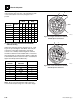
Note: The following chart shows which solenoids are
active with any given selection of the transmission shift
control switch (travel select lever) and gear select
position.
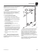
d. Upper and Lower Transmission Valve Body
Solenoid Testing
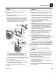
Inspect the solenoid connector plugs (Fig. 9-74, 1 and
Fig. 9-75, 6). Following the chart below, test each pin
connection on the upper transmission valve body
connector for continuity and shorting. Each solenoid
should have between 25.0 and 30.0 ohms of resistance
when testing with an ohm/volt meter. Replace a defective
solenoid valve. (Refer to Section 9.15.6, e. “Transmission
Upper Valve Body Solenoid Removal.”)
Note: All six solenoids within both upper and lower
solenoid valve body housings are of the same design.
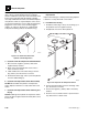
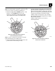
Figure 9-74 Upper Transmission Solenoid
Valve Body Pin Connections
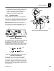
Figure 9-75 Lower Transmission Solenoid
Valve Body Pin Connections.
Upper Valve
Body
Lower Valve
Body
Driving
Direction
Speed Y1Y2Y3Y4Y5Y6
Forward 1 • • • •
Forward 2 • • • •
Forward3••••
Forward 4 • • •
Reverse 1 •• ••
Reverse 2 ••••
Reverse 3 • • • •
Solenoid Pin
Position
Active
Solenoid
Callout
1Y12
2Y23
3Y34
7Ground5
4Y47
5Y58
6Y69
7Ground10
MT1090
5
4
3
1
2
MT1100
10
9
7
8
6