
Service Manual Manual


Section 9 Hydraulic System
Model 6036/6036T S/N 9B0500 thru 14833
9-69
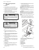
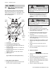
1. Main Control Valve
2. Cotter Pin
3. Retaining Pin
4. Linkage
5. Capscrew
6. Washer
7. Locknut
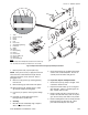
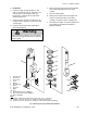
Fig. 9.39 Relief Valves
1. O-ring
2. Housing
3. Check Valve Poppet
4. Backup Ring
5. O-ring
6. Relief Valve Poppet
7. Piston
8. Piston Spring
9. O-ring
10. Backup Ring
11. O-ring
12. Plug
13. Pilot Poppet
14. Pilot Spring
15. Adjustment Screw
16. O-ring
17. Jam Nut
18. Acorn Nut
Main Relief Valve
Port Relief Valve
Fig. 9.38 Main Control Valve Installation
1
5
2
3
4
6
7
9
16
18
17
15
14
13
12
11
10
1
2
3
4
5
6
7
8
1
2
3
4
5
6
7
8
9
16
18
17
15
14
13
12
11
10
MA4070
MA4090
MA4080