Service Manual Model 6036 S/N 9B0500 thru 14833 8990163 Revised February 11, 2005
Effectivity Page August, 1997 - 001 - Original Issue February 11, 2005 - B - Replaced all branding with JLG.
Effectivity Page B Model 6036 S/N 9B0500 thru 14833
SECTION CONTENTS Section Subject Section 1 Safety Practices ................................................................................ 1-1 Section 2 General Instructions .......................................................................... 2-1 Section 3 Boom ................................................................................................. 3-1 Section 4 Operator's Cab ..................................................................................
This Page Left Blank Intentionally
Section 1 Safety Practices SECTION 1 SAFETY PRACTICES CONTENTS Par Title Page 1.1 INTRODUCTION ................................. 1-1 1.2 SIGNAL WORDS ................................ 1-1 1.3 PERSONAL CONSIDERATIONS ........ 1-2 1.4 EQUIPMENT CONSIDERATIONS ...... 1-2 1.5 GENERAL CONSIDERATIONS .......... 1-3 1.6 OPERATIONAL CONSIDERATIONS ............................ 1-3 1.7 FINAL WORD ...................................... 1-4 1.
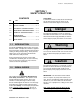
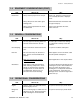
Section 1 Safety Practices 1.3 PERSONAL CONSIDERATIONS Item Why Clothing Do not wear loose clothing or jewelry. Improper clothing can catch on controls or moving parts and cause accidents and/or injury. Eye Protection Always wear appropriate eye protection when chiseling, grinding, discing, welding, painting, when repairing hydraulic systems, or checking, testing or charging the battery. Permanent eye damage can be caused if foreign matter enters the eye.
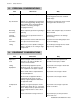
Section 1 Safety Practices 1.4 EQUIPMENT CONSIDERATIONS (CONT.) Item Hand Tools 1.5 What to do Why Always use the proper tool for the job. Many cuts, abrasions, and/or injuries are caused by defective or improper tools. Always keep tools clean and in good working order. Well maintained tools work better and may prevent injury. Always use the Special Service Tools recommended. These tools will reduce the work, labor and costs.
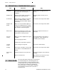
Section 1 Safety Practices 1.6 OPERATIONAL CONSIDERATIONS (cont.) Item What to do Why Ventilation Avoid prolonged running of the engine in a closed area with inadequate ventilation. Exhaust fumes are highly toxic and can kill. Radiator Cap Always turn the radiator cap slowly to the first stop to relieve pressure. Escaping coolant can burn you seriously. Soft Ground Never work on a forklift on soft ground. Check for additional ballast. Seek assistance and install suitable supports if necessary.
Section 2 General Instructions SECTION 2 GENERAL INSTRUCTIONS TABLE OF CONTENTS Par. Title Page Par. Title Page 2.1 INTRODUCTION ................................. 2-2 2.2 CLEANING .......................................... 2-2 2.3 REPLACEMENT ................................. 2-2 2.4 HOSES AND TUBES .......................... 2-2 2.4.1 2.4.2 Inspection .................................................... 2-2 Installation ................................................... 2-2 2.
Section 2 General Instructions 2.1 INTRODUCTION Appropriate service methods and proper repair procedures are essential for safe, reliable operation of the forklift and safety of the individual doing the work. This maintenance manual provides general directions for accomplishing service and repair work with tested, effective techniques. Following them will assure reliability. There are many variations in procedures, techniques, tools, and parts for servicing vehicles, as well as work skills.
Section 2 General Instructions 2.5 BEARINGS 2.5.1 Removal 1. Bearings should never be removed unless absolutely necessary. Always use the recommended puller to reduce the risk of bearing or related component damage. 2. When bearings or bushings are removed, check that the bearing is free from discoloration, nicks, scuffing, and signs of overheating. If in doubt, replace the bearing or bushing. 2.5.2 Cleaning the oil temperature.
Section 2 General Instructions 2.7.4 Straight Thread O-ring Fitting (non-adjustable) 1. Make sure both threads and sealing surfaces are free of burrs, nicks, scratches, or any foreign material. 2. Lubricate O-ring with light coating of oil. 3. Torque as follows: SAE 2.8 PAINTING Unless otherwise specified, paint all components as follows: 2.8.1 Orange Paint Use orange paint on all components except as specified in paragraphs 2.8.2 and 2.8.3. P/N 8528074 ......................
Section 2 General Instructions 2.9 AFTER SERVICE STARTUP AND CHECKS 2.9.1 Starting After Servicing NOTE: Refer to Owners/Operators Manual for engine cold start procedure. 1. Check fluid levels. 3. If a hydraulic component failed and contaminated the system, flush the system, clean the reservoir and replace the filter. 4. Following normal hydraulic component servicing, check hydraulic fluid level and replenish as required. 5. Start forklift and bleed systems of air. 6.
Section 2 General Instructions 2.9.10 After Axle Servicing 1. Check fluid levels. 2. Check torque of drive shaft yoke hardware. 3. Check wheel nut torque. 4. Check toe-in if required. 5. Lubricate all grease points. 6. Refer to Dana Service Manual for “SECTION 1 - General Information”. 2.10 FLUID LEVELS AND LUBRICATION TABLE 1 Recommended oils for DANA SPICER® axles P/N 070BP126-13 (front axle) and 070BP139-2 (rear axle) w/graphite based friction discs. BRAND DESCRIPTION Amoco Amoco 1000 Case IH (J.
Section 2 General Instructions 2.10.2 Hydraulic Reservoir With the oil cold and the forklift on a level surface and all hydraulic cylinders retracted, check the sight gauge on the right side of the main frame. The oil level should be visible in the gauge window. If it is not, open the locked hydraulic fill access door. Remove the fill cap and add MIL-L-2104C Oil as required to bring the oil level up to the minimum oil level line on the adjacent decal. 2.10.
Section 2 General Instructions Notes 2-8 6036/6036T S/N 9B0500 thru 14833
Section 3 Boom SECTION 3 BOOM CONTENTS Par. Title 3.1 Page 3.1 BOOM ASSEMBLY .............................. 3-1 3.1.1 3.1.2 3.1.3 3.1.4 3.1.5 3.1.6 3.1.7 3.1.8 3.1.9 3.1.10 Inner Boom Replacement ........................... 3-1 Intermediate Boom Replacement ............... 3-3 Outer Boom Replacement .......................... 3-5 Chain Replacement .................................... 3-9 Chain Lubrication ...................................... 3-10 Chain Tension Check ...............................
Section 3 Boom c. Installation INNER BOOM BASE END PIN QUICK ATTACH PIVOT PIN WITH GREASE FITTING GOOSENECK GRILLE TILT CYLINDER LOCK PIN QUICK ATTACH ASSEMBLY ROD END PIN MA0021 Fig. 3.2 Gooseneck 2. Prepare to replace the inner boom, Fig. 3.2, by removing the grille tilt cylinder as described in paragraph 9.5.8.a. 3. Remove the quick attach pivot pin, Fig. 3.2, and quick attach assembly from the gooseneck. 4. Remove the rear boom cover, Fig. 3.1. 5.
Section 3 Boom CAPSCREW ENDS TO BE FLUSH TO 0.19" (5 mm) RECESSED IN WEAR PAD INSERT GAP MUST BE 0.07 TO 0.13" (1,8 TO 3,3 mm) PAD, SPACER, INSERT (2), LOCK WASHER (6), FLAT WASHER (6), 3/8-16 X 1-3/4" CAPSCREW (6), 14 GA SHIM GAP MUST BE 0.07 TO 0.13" (1,8 TO 3,3 mm) INTERMEDIATE BOOM INNER BOOM CAPSCREW ENDS TO BE FLUSH TO 0.
Section 3 Boom 4. Use a sling and a suitable hoist to slide the intermediate boom out the front of the outer boom. 5. Record the number of shims beneath each wear pad as you remove the rear bottom, Fig. 3.6, and all front wear pads, Fig. 3.5, from the intermediate boom. 6. Examine the chain sheaves for wear and replace if necessary. b. Inspection and Replacement 1. Inspect the boom and welds and contact JLG if structural damage is detected. Fig. 3.5 Front Wear Pads Attached to Intermediate 2.
Section 3 Boom PAD, INSERT (1), LOCK WASHER (3), FLAT WASHER (3), 3/8-16 X 7/8" CAPSCREW (3) PAD, INSERT (1), LOCK WASHER (3), FLAT WASHER (3), 3/8-16 X 7/8" CAPSCREW (3) GAP MUST BE 0.07 TO 0.13" (1,8 TO 3,3 mm) GAP MUST BE 0.07 TO 0.13" (1,8 TO 3,3 mm) GAP MUST BE 0.07 TO 0.
Section 3 Boom OUTER BOOM INTERMEDIATE BOOM INNER BOOM HOSES HOSE GUIDE CLAMP TUBING SUPPORT PLATE CONNECTION TO MAIN CONTROL VALVE GRILLE TILT CYLINDER MA0081 Fig. 3.8 Grille Tilt Cylinder Hoses 6. Disconnect and cap or plug the grille tilt cylinder tubing, extend cylinder tubes and bulkhead fittings in support plate, Fig. 3.8, below the rear opening of the boom. 7. Loosen clamps that hold the tubing to the bottom of the outer boom and remove the tubing from the outer boom. 8.
Section 3 Boom PAD, INSERT (1), LOCK WASHER (2), FLAT WASHER (2), 3/8-16 X 7/8" CAPSCREW (2) PAD, INSERT (1), LOCK WASHER (2), FLAT WASHER (2), 3/8-16 X 7/8" CAPSCREW (2) GAP MUST BE 0.07 TO 0.13" (1,8 TO 3,3 mm) GAP MUST BE 0.07 TO 0.13" (1,8 TO 3,3 mm) GAP MUST BE 0.07 TO 0.
Section 3 Boom INNER BOOM SHOULDER SCREW AND LOCKNUT CLEVIS 1-1/2" TO 2-1/2" (38 mm TO 63 mm) YOKE CHAIN LINK PIN AND RETAINING RING INTERMEDIATE BOOM SHOULDER SCREW AND LOCKNUT EXTEND CHAIN BLOCK EXTEND CHAIN, LOCKNUT AND FLAT WASHER OUTER BOOM INNER BOOM INTERMEDIATE BOOM OUTER BOOM RETRACT CHAIN LOCKNUT AND FLAT WASHER RETRACT CHAIN CHAIN SUPPORT RETRACT CHAIN PLATE SHOULDER SCREW AND LOCKNUT (S/N 2516 & AFTER) INNER BOOM RETRACT CHAIN LOCKNUT AND FLAT WASHER (S/N 2515 & BEFORE) MA0111 Fi
Section 3 Boom 3.1.4 Chain Replacement Two chains extend the inner boom and one chain retracts it. 8. Refer to paragraph 3.1.5 and lubricate the chain. 9. Refer to paragraphs 3.1.6 and 3.1.7 and check and adjust the chains. Extend Chains Retract Chain IMPORTANT: Replace extend chains in pairs or sets ONLY. a. Removal a. Removal 1. Fully retract the boom. 1. Fully retract the boom. 2. Remove the rear boom cover. 2. Remove the rear boom cover. 3.
Section 3 Boom 3.1.5 Chain Lubrication BOOM EXTEND CHAINS 250 Hour Intervals 1. Remove the rear boom cover from the outer boom. 2. Extend and retract the boom several times applying Aerosol .0002 Waxy Film Rust Inhibitor, TRAK part number 8526405. 3. With the boom fully extended, apply multipurpose lithium based grease to the extend chain using a brush or grease gun. EXTEND CHAIN SHEAVE LUBE FITTING 4. Install the rear boom cover on the outer boom.
Section 3 Boom Adjustment is accomplished using extend chain adjustment locknuts, Fig. 3.14. a. Chain Locknut Functions Loosen extend chain locknuts to extend the inner boom and increase extend chain sag. Tighten outer boom retract chain locknut to retract the inner boom and decrease extend chain sag. b. Adjusting Procedure 1. Raise the boom to a horizontal (level) position. Fully extend the boom, then retract it 2", which is 1" per section (51 mm which is 25,5 mm per section). 2.
Section 3 Boom IMPORTANT: Inspect the pads as follows: • Replace wear pads that are less than 0.375" (9,5 mm) thick. • Each boom wear pad is manufactured with a convenient wear pad indicator. This is the angled cut at each end of all wear pads, Fig. 3.16. The total thickness of a new wear pad is .625" (15,9 mm), the angled cut will provide a total wear thickness of .25" (6,4 mm). This will leave approximately .375" (9,5 mm) of total unused material.
Section 3 Boom Pull hoses, through hose clamps, 1" further to tension hoses Inner boom hose clamps and capscrews 3.1.10 Long Term Storage Preparation Remove rust and corrosion from sliding surfaces and coat with grease. 180° B Hose must have a minimum of 180° of contact with pulley C A A B (FIG. 3.13) MA6040 A D Fig. 3.
Section 3 Boom 3.2 EMERGENCY BOOM LOWERING RETAINER NUT COUNTERBALANCE VALVE 3.2.1 Loss of Engine Power or Hydraulic Pump Failure If you lose engine power or hydraulics with an elevated boom, lower the boom to the ground by using the following procedure: Warning DO NOT get under a raised boom unless the boom is blocked up. Always block the boom before doing any servicing which requires the boom to be up.
Section 3 Boom 3.2.2 Hydraulic Line Failure Warning In the event of a hydraulic line failure in any of the boom control circuits, extreme CAUTION must be taken when attempting to lower an elevated load. Hydraulic oil under high pressure will escape through the fault in the line which may result in the boom retracting or lowering at a rapid rate. DO NOT perform this procedure unless you are absolutely sure of what you are doing.
Section 3 Boom 3.3 QUICK ATTACH ASSEMBLY 2. Install quick attach assembly (10) on gooseneck (7) with quick attach pin (8). Lock the pin in place with capscrew and locknut (6). The quick attach assembly, Fig. 3.21, provides a structure on which an attachment may be installed or removed from the forklift. 3. Lubricate the pin through grease fittings using a good grade of multi-purpose lithium based grease. a. Removal 2. Remove the attachment from the quick attach. 4.
Section 3 Boom 3.4 TROUBLESHOOTING Trouble Probable Cause Remedy Reference Broken hydraulic line and/or connection leaks. Locate break and/ or stop leaks. Faulty Extend/Retract Cylinder. Repair Cylinder. Section 9 Faulty components in Extend/Retract hydraulic circuitry. Troubleshoot components and repair or replace components. Section 9 Broken chains or chain connections. Repair or replace chains. See para. 3.1.4 Broken Hydraulic line and/or connection leaks.
Section 3 Boom 3.5 SPECIFICATIONS For 13.00-24 10 ply Tires For 15,00-19.5 12 ply Tires Maximum lift height-boom extended 35 ft. 1 in. (11 m) 35 ft. 5 in. (10,8) Maximum lift height - boom retracted 20 ft. 1 in. (6,1) 19 ft. 3 in. (5,79) Maximum below grade depth – boom 39.5 in. (100,3 cm) 40.5 in. (102,9 cm) Maximum reach from front of tire 22 ft. 5 in. (6,8 m) 22 ft. 10 in. (7,0 m) Maximum reach at maximum lift 45.0 in. (114,3 cm) 50.5 in. (128,3 cm) –26.0 in. (–66,0 cm) –19.6 in.
Section 4 Operator's Cab SECTION 4 OPERATOR'S CAB CONTENTS Par. Title Page 4.1 SEAT .................................................. 4-1 4.2 MECHANICAL HAND CONTROLS .... 4-1 4.2.1 4.2.2 Steering Wheel and Steering Unit ............. 4-2 Travel Select and Range Select Levers ........................................................ 4-2 Boom Control and Grille and Frame Tilt Joysticks .............................................. 4-4 4.2.3 4.3 ELECTRONIC JOYSTICK .................. 4-5 4.3.
Section 4 Operator's Cab TRAVEL SELECT LEVER FOR FORWARD-F, NEUTRAL-N, AND REVERSE-R RANGE SELECT LEVER FOR LOW-1, MEDIUM-2, AND HIGH-3 BELL CRANKS GATE PLATE SHIFTER ASSEMBLY CLEVIS PIN, WASHER, AND COTTER PIN SWIVEL COTTER PIN AND WASHER LOCKNUT CABLE MOUNTING STRAP REVERSE SWITCH CONTROL CABLE ANGLE BRACKET LOCKNUT AND CAPSCREW REVERSE SWITCH LEAD WIRES CLAMP MA0141 Fig. 4.3 Shifter Assembly 4.2.
Section 4 Operator's Cab b. Transmission Cable Removal Maintenance 1. Prepare to clean and lubricate the spring, disk and ball in each travel and range select lever mechanism by removing the cotter pins, washers and clevis pins that secure each lever to the shifter assembly. Remove the levers from the shifter assembly. 2. Clean each lever spring, disk, and ball with an approved solvent. Replace defective or damaged parts as required. Apply a multipurpose grease to each disk, spring, and ball. 3.
Section 4 Operator's Cab 4.2.3 Boom Control and Grille and Frame Tilt Joysticks The Boom Control Joystick raises, lowers, retracts, and extends the boom. The Grille / Frame Tilt Joystick tips the carriage up or down and tilts the frame left or right. See the Owners/Operators Manual for operational descriptions. A control cable attached to each joystick assembly, Fig. 4.5, terminates at a valve section on the main control valve, Fig. 4.6. JOYSTICK ASSEMBLY a. Joystick Assembly Removal 1.
Section 4 Operator's Cab 4. Install the covers on the joystick assembly. 5. Install the lower panel. b. Joystick Control Cables Removal 1. Remove the lower panel which is below the side console. 2. Remove the covers from the joystick assembly, Fig. 4.5. 3. Loosen the lock screw until the control cable, with lock screw and cable bushing, can be removed from the slider. 4. Unthread cable bushing from cable and remove lock screw from cable. 5. Remove the transmission cover. 6. Remove the clamp, Fig. 4.
Section 4 Operator's Cab 4.3.3 Electronic Joystick Calibration (without TLC) Locate the forklift in an area where the boom can be safely operated in all positions, out-of-doors and clear of power lines. A small screwdriver with a 3 inch long shank and a 1/8 inch wide blade will be required. CIRCUIT BOARD CONNECTOR STRIPS Carefully remove the four plastic caps located on the left side of the right console below the electronic joystick, Fig. 4.8.
Section 4 Operator's Cab 1. Through the top two adjusting screw holes you will calibrate the Raise/Lower functions, Fig. 4.8. • Adjustment screw through hole Position 1 will adjust the maximum amount of oil available (speed) to move the hoist cylinders (on later joysticks this adjuster has been sealed in the maximum speed position and cannot be adjusted, skip step 2). • Adjustment screw through hole position 2 calibrates the dead band (feathering for the Raise/ Lower function. 2.
Section 4 Operator's Cab 6. Connect the ohmmeter between the “T” and “C” terminals on the extend/retract connector strip, Fig. 4.9. Move the joystick handle fully into the boom extend position until a resistance reading is measured on the ohmmeter. Record this reading. Move the joystick fully into the boom retract position. Record this reading. 4.3.
Section 4 Operator's Cab 8. Reconnect the wires from the upper drive module (raise/lower) and lower drive module (extend/retract) to the appropriate connector strips as follows, Fig. 4.10. 4.3.6 Electronic Joystick Removal and Replacement without TLC The following instructions describe how to remove and replace an electronic joystick without TLC (Total Load Control). For a forklift with TLC refer to the SKY TRAK TLC System Maintenance Manual. • Gray wire to terminal “T”. • Yellow wire to terminal “C”. 9.
Section 4 Operator's Cab 4. Remove driver module support bracket from console cover, Fig. 4.11. BRAKE VALVE PUSH ROD JAM NUT 5. Remove joystick weather boot clamp, Fig. 4.11. 6. Remove joystick mounting screws and separate joystick from console cover. SPRING YOKE SHAFT CLEVIS PIN 7. Tag and disconnect electrical leads from joystick, Fig. 4.10. ADJUSTING NUT 8. Reconnect the wires as shown in Fig. 4.10. 9.
Section 4 Operator's Cab PEDAL LIMIT STOP SCREW CAB FLOOR LOCKNUT WASHER CLAMP LEVER ASSEMBLY CABLE SUPPORT CLEVIS PIN AND LOCK CLIP THROTTLE CABLE SPRING JAM NUT MA0191 CLEVIS Fig. 4.13 Throttle Pedal 2. Install the spring on the pedal and hook the other end over the support inside the console. 3. Slide push rod into brake valve and secure the yoke to the pedal with clevis and cotter pins. 4. Check the brake valve capscrews to be sure they are torqued to 30 lb-ft (40,8 Nm). a.
Section 4 Operator's Cab 2. Adjust the limit stop screw until it touches the pedal. 7. Remove the long clevis and jam nut from the cable end. 3. Tighten the locknut to 120 to 125 lb-inch (13,6 to 14,1 Nm). 8. Remove the throttle cable from the forklift. Installation 4. Check engine rpm at full throttle. If not 2600 to 2860 rpm, readjust the limit stop screw. IMPORTANT: During the full throttle check • operate no hydraulic function, • do not steer, and • be sure the transmission is in neutral. b.
Section 4 Operator's Cab 4.5 3. Tighten “preset” pivot bolt to a 3/16" (5 mm) gap as shown in Fig. 4.16. REAR VIEW MIRRORS The forklift has two rear view mirrors. • A 6-1/2 by 10" flat glass mirror on the cab frame to the left of the operator. • A 6-1/2 by 6" convex glass mirror on the forklift frame to the right of the operator. The mirrors have an outer gasket for edge shock protection. If a mirror shatters, a replacement mirror can be installed in the mirror head. 4.5.
Section 4 Operator's Cab Notes 4-14 Model 6036/6036T S/N 9B0500 thru 14833
Section 5 Wheel Assembly, Tires, and Axle SECTION 5 WHEEL ASSEMBLY, TIRES, AND AXLE CONTENTS Par. Title Page 5.1 WHEEL ASSEMBLY AND TIRE ......... 5-2 5.1.1 Removing Hydrofill from Tire or Tube within Tire ......................................... 5-4 Demounting Tire ........................................ 5-5 Removing Wheel from Forklift ................... 5-5 Demounting Tire from Three Piece Wheel ............................ 5-5 Demounting Tire from Single Piece Wheel ..........................
Section 5 Wheel Assembly, Tires, and Axle 5.1 WHEEL ASSEMBLY AND TIRE Warning Whenever you remove tire(s) and wheel(s) from forklift: • Position forklift on a flat, hard surface and support forklift with approved jack stands. • Use appropriate safety glasses, safety shoes and appropriate clothing and equipment. • Do not wear rings or jewelry or use clothing or hair styles that could become caught in machinery or pinch points such as those created between tire and hub.
Section 5 Wheel Assembly, Tires, and Axle SOME TIRES HAVE THIS INSTRUCTION EMBOSSED IN SIDE WALL: DRIVING TIRES MUST ROTATE AS THE ARROW POINTS (OTHER TIRES MUST ROTATE IN THE OPPOSITE DIRECTION) VALVE POSITION FOR FILLING TIRE WITH HYDROFILL AND AIR AND CHECKING TIRE PRESSURE ARROW POINTS TO RIGHT ON BOOM SIDE OF FORKLIFT MA0212 A SS E WH EL M Y BL E TIRE HUB WHEEL LUG NUT MA0214 MA0211 VALVE POSITION FOR DRAINING HYDROFILL FROM TIRE NOTE DIRECTION OF TREAD PATTERN ARROW POINTS TO LEFT ON
Section 5 Wheel Assembly, Tires, and Axle FIXED SIDE FLANGE AND TIRE SEAT LOOSE SIDE FLANGE AND TIRE SEAT RIM BASE LOCK RING EMBOSSED VALVE HOLE TR618A AIR-WATER TYPE VALVE O-RING SEALING RING MA0221 Fig. 5.2 Wheel Assembly with T-Type Rim and Fixed Back Flange (S/N OF1191 & Before) Tire and wheel maintenance is covered in the following paragraphs: 5.1.1 Removing Hydrofill from Tire or Tube within Tire 5.1.1 1.
Section 5 Wheel Assembly, Tires, and Axle START BEAD ON THIS SIDE OF RIM DEEP WELL MA0231 Fig. 5.3 Wheel Assembly with Single Piece Rim (S/N OF1192 & After) 5.1.2 Demounting Tire IMPORTANT: Always completely deflate tire as described in paragraph 5.1.1 before you attempt to demount tire. 1. Be sure you’ve read and understood the warning notices and general instructions in paragraph 5.1. 2. To remove a wheel from the forklift refer to paragraph 5.1.3. 5.1.
Section 5 Wheel Assembly, Tires, and Axle 5.1.5 Demounting Tire from Single Piece Wheel (S/N OF1192 & After) CLIP-ON CHUCK IMPORTANT: Always completely deflate tire as described in paragraph 5.1.1, before you attempt to demount a tire. CORE EJECTOR BODY CORE REMOVER 1. Be sure you’ve read and understood the warning notices and general instructions in paragraph 5.1. EJECTOR CHUCK PACKING NUT 2. Place the wheel and tire assembly on the floor on blocks with the narrow ledge on the bottom, Fig. 5.3.
Section 5 Wheel Assembly, Tires, and Axle 9. Remove the valve stem from the rim base. 5.1.9 Mixing Hydrofill Solution 10. Refer to paragraph 5.1.12 for tire mounting instructions. Prepare the hydrofill mixture by pouring calcium chloride into water; never add water to calcium chloride as considerable heat is generated in this mixing process. Let the solution cool to atmospheric temperature before pumping it into the tire.
Section 5 Wheel Assembly, Tires, and Axle 5. Inspect both sides of the tire to be sure beads are evenly seated. If not, completely deflate tire, unseat beads and repeat entire mounting procedure. 6. Lower jack until tire is slightly deflected. With pump not running and the pump control handle at CHECK position, connect ejector and remove core housing as described in paragraph 5.1.1. 7. After connection is made, bleed pressure down to about 5 psi (34,4 kPa) by moving pump control to EVACUATE.
Section 5 Wheel Assembly, Tires, and Axle 6. Lubricate a new rubber O-ring. Place O-ring in groove on one side and stretch O-ring snapping it into place rather than rolling it into place. Then lubricate the entire O-ring groove areas with an approved vegetable-based lubricant. NOTE: It may be necessary to hold the side flange down with the flat end of the tire iron to expose the O-ring groove. 7. Check the components to make certain they are correctly assembled .
Section 5 Wheel Assembly, Tires, and Axle 5.1.15 Installing a Wheel on the Forklift shows was started by the overheated condition that developed when the unit was towed at high speed. 1. Be sure you’ve read and understood the warning notices and general instructions in paragraph 5.1. 2. Remove the wheel assembly from the safety cage and place it on the axle hub. 3. Secure the wheel assembly to the axle hub with ten wheel lug nuts. Torque the nuts to 450 to 500 lb-ft (610 to 678 Nm).
Section 5 Wheel Assembly, Tires, and Axle 5.2 AXLE ASSEMBLY The axle assembly rotates and turns the wheels. Both front and rear axles consist of a differential carrier assembly, a left and right axle steering joint, and a left and right wheel end, Fig. 5.6. The front axle wheel ends contain service brakes. If the forklift has a turbocharged engine both the front and rear axle wheel ends contain service brakes.
Section 5. Wheel Assembly, Tires, and Axle IMPORTANT: • When replacing a fastener, replace it with one of equal or higher grade and quality. Torque fasteners are recommended for the application. • Some service operations require the use of tools specifically designed for the purpose. Use the special tools when and as recommended. • Hammering on end yokes or flanges to remove or install them is not only destructive to the yoke or flange itself, but can also cause serious internal damage.
Section 5. Wheel Assembly, Tires, and Axle Warning Wait for the hydraulic fluid to cool before servicing any hydraulic component. Hot hydraulic fluid can cause severe burns. 3. Place adequate support under the frame so that it will remain in place when the axle assembly is removed. 4. Remove the wheels from the axle as described in paragraph 5.1.3. 5. Use floor jacks or install a suitable hoist at the ends of the axle. Take up the slack. 6.
Section 5. Wheel Assembly, Tires, and Axle 27 28 41 26 40 39 42 37 36 38 24 34 35 32 23 30 43 29 31 21 20 19 22 10 13 17 18 11 12 11 25 10 PA0332 8 14 7 NEVER reuse a Fatigue Fighter bolt ALWAYS replace with new ones 16 15 5 6 9 3/8" FATIGUE FIGHTER BOLT PROPER TORQUE 45 lb-ft (61 Nm) 4 1. 2. 3. 4. 5. 6. 7. 8. 9. 10. 11. 12. 13. 14. 15.
Section 5. Wheel Assembly, Tires, and Axle 5. Connect hydraulic hoses as required to steering cylinders, service brakes and park lock. Bleed the lines to the service brakes and park lock. 6. Remove the hoist from the ends of the axle. 7. Install the wheels on the axle as described in paragraph 5.1.15. 8. Remove the support from under the frame. Warning Before starting the engine be sure all hydraulic connections are tight and all tools are removed from the forklift. 9. Start the engine.
Section 5. Wheel Assembly, Tires, and Axle 30 31 29 28 26 24 25 27 23 19 10 13 11 12 22 11 10 20 18 8 7 4 17 16 5 15 14 6 9 2 PA0322 1. 2. 3. 4. 5. 6. 7. 8. 9. Wheel End Assembly Screw, self-locking Planetary Gear Assembly Flange, planetary drive Plug, drain/fill Plug Pin, roll Shaft, planet gear Washer, drive flange 10. 11. 12. 13. 14. 15. 16. 17. Washer, keyed Bearing, single roller Washer, planet gear Gear, planet Ring, retaining Gear, sun spur Spacer, flat Gear, planetary ring 18 19.
Section 5. Wheel Assembly, Tires, and Axle 3. After drying, components should be lightly coated with oil or rust preventive to protect them from corrosion. c. Inspection and Replacement 1. Replace all discs and plates as a set if any of the following conditions exist: • friction material groove depth on any disc is less than 0.005" (0,127 mm), • plates are warped as determined by a straight edge, or • any plate or disc is heat damaged. 2. Replace all O-rings regardless of condition. 3.
Section 5 Wheel Assembly, Tires, and Axle 22 23 24 25 11 10 9 26 7 8 25 24 1 5 4 5 17 18 23 6 3 16 22 19 2 20 21 13 12 15 14 21 20 19 18 17 1. 2. 3. 4. 5. 6. 7. Shaft and Joint Assembly Shaft, outer Cross Assembly Bearing Race Assembly Ring, retaining Yoke, center Shaft, inner yoke, left 8. 9. 10. 11. 12. 13. 16 PA0312 Shaft, inner yoke, right Deflector, seal Seal, oil Bushing, spindle Knuckle Assembly Stud, dowel 14. 15. 16. 17. 18. 19.
Section 5 Wheel Assembly, Tires, and Axle a. Disassembly 1. Refer to page 13 through 16 of Spicer® Dana Maintenance Manual for Axle Models PS/PR7036 for removing and disassembling the drive flange and wheel end hub. 2. On an axle with service brakes: (a) Remove lining stop plates (14 and 17, Fig. 5.8) and disc assemblies (18). 5. Tap the spindle with a soft-faced hammer to loosen the knuckle assembly (12, Fig. 5.10). Remove the spindle assembly. 6. Replace oil seal or bronze bushing (42, Fig. 5.
Section 5 Wheel Assembly, Tires, and Axle 4. Replace roller bearing cups (24) or cones (23) if any are worn, pitted, or damaged. 5. Replace oil seals (10 and 22) regardless of condition. d. Retaining Ring Inspection 1. Place the forklift in “Crab Steer” mode and turn the steering wheel full left to access shaft assemblies on the right side of the vehicle 2. Using a flashlight, visually inspect the right front shaft assembly retaining rings through the opening between the axle housing and steering knuckle.
Section 5 Wheel Assembly, Tires, and Axle turn and align any hole in the nut with a major spline on the spindle. Mark the end of the aligned spline on the edge of the spindle. Make sure the hub rotates freely. (d) Install roll pin (19) on the back face of planetary ring gear (17) and mark its location on the front face of the gear. (e) Install planetary ring gear, making sure roll pin is locked into locknut hole.
Section 5 Wheel Assembly, Tires, and Axle 2 17 10 9 9 9 11 7 15 3 6 8 4 8 8 24 12 19 1 20 22 21 13 23 16 18 5 14 PA0281 1. 2. 3. 4. 5. 6. Screw, socket head cap (4) Plate, cover Spline, outer Spring, red (12) Plate, pressure Plate, spring 7. 8. 9. 10. 11. 12. Screw, socket head cap (4) Disc, rotor (7) Plate, lining (7) Plate, thrust Bolt, socket head shoulder (4) Screw, bleeder 13. 14. 15. 16. 17. 18. Ring, retainer Bearing Ring, retainer Seal, oil Seal, oil Seal, case (2) 19. 20. 21.
Section 5 Wheel Assembly, Tires, and Axle PIN LINING PLATE THRUST PLATE CAPSCREW SHOULDER BOLT MA0291 Fig. 5.14 Plate and Disc Alignment c. Cleaning and Drying e. Assembly 1. Clean all parts with approved petroleum based cleaner. Refer to page 55 of Spicer® Dana Maintenance Manual for Axle Models PS/PR-7036 for assembly instructions. 2. Use clean lint free towels to dry components after cleaning. DO NOT dry bearings by spinning with compressed air.
Section 5 Wheel Assembly, Tires, and Axle 7 8 10 9 46 8 10 41 7 9 11 5 43 42 12 43 2 3 4 4 3 44 2 13 17 18 16 14 45 15 22 19 23 24 28 29 25 26 30 31 35 27 22 34 32 39 33 40 21 PA1360 37 38 36 1. 2. 3. 4. 5. 6. 7. 8. 9. 10. 11. 12. 13. 14. 15. 16. 17. 18. 19. 20. 21. 22.
Section 5 Wheel Assembly, Tires, and Axle 8 10 7 9 41 8 10 11 45 42 40 7 9 5 12 42 2 3 4 4 3 2 13 14 17 16 43 15 18 23 22 19 44 21 24 29 28 25 26 31 22 27 33 34 30 32 36 39 35 PA1530 37 38 1. 2. 3. 4. 5. 6. 7. 8. 9. 10. 11. 12. 13. 14. 15. 16. 17. 18. 19. 20. 21. 22.
Section 5 Wheel Assembly, Tires, and Axle PIVOT PIN KNUCKLE STEER CYLINDER BALL JOINT TIE ROD BALL JOINT KNUCKLE OA0192 Fig. 5.17 Axle Grease Points 5.3 Warning • Do not attempt carrier and differential removal and installation and differential and pinion disassembly and assembly without thoroughly understanding instructions in Spicer® Dana publications and correspondence which applies to your forklift.
Section 5 Wheel Assembly, Tires, and Axle Level Check (250 hour intervals) AXLE FILL AND LEVEL PLUG 1. Level the forklift, ground the carriage, shut off the engine, and engage the park lock. Be sure that the arrow on the wheel end housing is pointing down (Fig. 5.19). 2. Clean the area around the magnetic drain plug and remove the plug. AXLE DRAIN PLUG OA0422 Fig. 5.18 Axle Fill and Drain Plugs Change (1000 hour intervals) 1. Place a receptacle under the axle housing drain plug (Fig. 5.18). 2.
Section 5 Wheel Assembly, Tires, and Axle 5.4 SPECIFICATIONS Oil Capacity of Differential Housing 18 qts (17 liters) 5.5 TROUBLESHOOTING Troubleshooting instructions are provided on pages 56 through 59 of Spicer® Dana Maintenance Manual for Axle Models PS/PR-7036. 80W-90 with EP properties: Amoco MP Gear Lube 80W90 Benz Multi-Purpose 80W90 Mobil Mobilube HD 80W90 Shell Spirax 80W90 Texaco Multi Gear Lube 80W90 Oil Capacity of Wheel End Front-54 oz.
Section 6 Drive Shafts and Drop Box SECTION 6 DRIVE SHAFTS AND DROP BOX CONTENTS Par. Title Drive Shafts–Drop Gear Box to Axle Page 6.1 DRIVE SHAFTS ................................. 6-1 6.1.1 Drive Shaft Servicing ................................. 6-1 6.2 DROP GEAR BOX FOR S/N 9N0941 AND BEFORE ................ 6-3 6.2.1 6.2.2 6.2.3 6.2.4 End Yokes ................................................. 6-3 Oil Seals ....................................................
Section 6 Drive Shafts and Drop Box SLEEVE ASSEMBLY DUST CAP SHAFT ASSEMBLY SPLIT RETAINING RING FELT SEAL DRIVE SHAFT SLEEVE ASSEMBLY DUST CAP SPLIT RETAINING RING DROP BOX INPUT SHAFT YOKE FELT SEAL CROSS ASSEMBLY GREASE FITTING BEARING ASSEMBLY RETAINING RING U-BOLT OR BEARING STRAP TRANSMISSION TO DROP BOX DRIVE SHAFT TRANSMISSION OUTPUT DROP BOX INPUT SHAFT YOKE MA0302 SHAFT YOKE SLIP JOINT DROP BOX TRANSMISSION OUTPUT SHAFT YOKES SLIP JOINT SLIP JOINT FRONT AXLE ASSEMBLY AXLE DRIVE
Section 6 Drive Shafts and Drop Box 9. Unscrew the dust cap and slide the sleeve assembly off the spline of the drive shaft. 10. Remove the dust cap, split retaining ring, and felt seal from the shaft assembly. c. Cleaning and Drying 7. Temporarily tape the two loose bearing caps to the cross so they do not fall off during assembly of drive shaft onto the forklift. f. Installation Drive Shaft–Transmission to Drop Gear Box 1. Disassemble and clean all parts using an approved cleaning fluid. 1.
Section 6 Drive Shafts and Drop Box OIL SEAL VENT/FILL PLUG END YOKE SCREW & WASHER END YOKE SCREW & WASHER OIL SEAL FRAME DROP BOX ASSEMBLY DROP BOX INSPECTION COVER CAPSCREW LEVEL PLUG (on late models) LOCK WASHER LEVEL PLUG (on early models) OIL SEAL END YOKE SCREW & WASHER DRAIN PLUG PA0261 Fig. 6.2 Exploded View of Drop Gear Box for S/N 9N0941 and Before 6.2.2 Oil Seals 6.2.3 Internal Inspection and Servicing a.
Section 6 Drive Shafts and Drop Box 6.3 DROP GEAR BOX FOR S/N 9N0942 AND AFTER 6.3.1 End Yokes a. Inspection Replace end yokes (23 and 24, Fig. 6.3) if worn or damaged. b. Removal To remove an end yoke, remove nut (12), washer (14), and end yoke (23 or 24, Fig. 6.3). c. Installation To install an end yoke, press yoke (23 or 24, Fig. 6.3) on shaft and secure with washer (14) and nut (12). 6.3.2 Oil Seals a. Inspection Replace oil seal (21, Fig. 6.3, if worn or damaged. b.
Section 6 Drive Shafts and Drop Box 11 13 9 8 8 9 20 4 23 21 5 14 2 8 12 16 9 6 8 15 9 7 9 20 16 8 3 10 12 1 22 14 26 18 21 17 24 9 8 PA1450 20 19 4 25 21 12 1. 2. 3. 4. 5. 6. 7. 8. 9. Housing Housing Closed Cover Open Cover (2) Input Pinion with 69 Teeth Intermediate Pinion with 67 Teeth Output Pinion with 69 Teeth Bearing Cup (6) Bearing Cone (6) 14 24 10. Hex Head Capscrew 3/8-16 x 1" (15) 11. Hex Nut 3/8-16 (14) 12. Lock Nut (3) 13. Lock Washer 3/8" (14) 14.
Section 6 Drive Shafts and Drop Box 6.3.7 Assembly of Drop Gear Box for S/N 9N0942 and After Only 1. If necessary, install dowels (16). 2. Press in matching bearing cups (8) and press on cones (9). 3. Place gears (5, 6, and 7) in housing and align the holes in the housing with the dowel pins. 4. Install and loosely tighten capscrews (15), lock washers (13) and nuts (11). 6.3.8 Installation of Drop Gear Box 1.
Section 6 Drive Shafts and Drop Box Notes 6-8 Model 6036/6036T S/N 9B0500 thru 14833
Section 7 Transmission SECTION 7 TRANSMISSION, CLARK SERIES 18000 CONTENTS Par. Title 7.1.1 Daily or 10 Hour Intervals Page 7.1 TRANSMISSION PREVENTIVE MAINTENANCE .................................. 7-1 7.1.1 7.1.2 7.1.3 Daily or 10 Hour Intervals ......................... 7-1 First 50 Hours and 500 Hour Intervals Thereafter .................................................. 7-1 1000 Hour Intervals ................................... 7-2 7.2 HOW TO TOW THE FORKLIFT .......... 7-2 7.
Section 7 Transmission 3. Remove sump plug and screen with gasket from housing, Fig. 7.3. Allow the transmission to drain completely. TRANSMISSION FILTER 4. Clean the plug and screen thoroughly with an approved solvent. 5. Install a new filter element as described in paragraph 7.1.2. DO NOT START ENGINE. 6. Install the cleaned drain plug and screen and gasket into the transmission sump housing. TRANSMISSION DIPSTICK OA0402 Fig. 7.2 Transmission Filter and Dipstick 6.
Section 7 Transmission 7.3 HOW TO DRAIN TRANSMISSION 7.6 The procedure for draining the transmission is described in paragraph 7.1.3. 6 TRANSMISSION REPLACEMENT If the transmission is to be replaced as a complete assembly, detach and transfer the following: • Tandem Pump • Transmission Temperature Switch • Transmission Connector Kit (from valve) • Two Side Mount Brackets (Neutral Start Switch comes with new transmission) 5 7.
Section 7 Transmission 7.
Section 7 Transmission 7.10 SPECIFICATIONS System Capacity (inc. filter and oil cooler) 4.3 gallons (16,3 liter) Filter Capacity 1 quart (0,95 liter) Transmission Oil (MIL-L-2104C) Castrol Deusol CRD Esso Essolube D-3HP Esso Essolube XD-3 Castrol Agricastrol HDD Shell Rimula CT Shell Rimula X Shell Rimula TX Converter: Outlet oil temperature Outlet pressure 180 to 200 °F (82 to 93 °C ) Transmission in Neutral.
Section 7 Transmission Notes 7-6 Model 6036/6036T S/N 9B0500 thru 14833
Section 8A Perkins Engine SECTION 8A ENGINE, PERKINS SERIES 4.236 AND T4.236 CONTENTS Par. Title Page SAFETY CONSIDERATIONS ...... 8A-2 8A.1 DISCLAIMER AND SCOPE ......... 8A-3 8A.2 STANDARD PRACTICES ............ 8A-3 8A.3 UNIFIED THREADS ..................... 8A-3 8A.4 ENGINE MAINTENANCE ............ 8A-3 8A.4.1 8A.4.2 Left and Right Sides of Engine ............ 8A-3 Maintenance Intervals .......................... 8A-3 8A.5 ENGINE MAINTENANCE Daily Before Operating Engine ..... 8A-3 8A.5.
Section 8A Perkins Engine Warning To protect yourself and others: • DO NOT smoke or operate engine during refueling. • DO NOT operate engine in the presence of a fuel spill or gas leak. Such combustible vapors when drawn into the engine can cause engine over-speeding, an explosion, fire and extensive personal injury and property damage. Before you operate in any hazardous environment consult a recognized authority in this field such as your engine distributor.
Section 8A Perkins Engine 8A.1 DISCLAIMER AND SCOPE OF THE INSTRUCTIONS These instructions are written for world wide use. In territories where legal requirements govern engine smoke emission, noise, safety factors etc., then all instructions, data and dimensions given must be applied in such a way that, after servicing (preventive maintenance) or repairing the engine, it does not contravene the local regulations when in use. IMPORTANT: These instructions cover only the routine maintenance of the engine.
Section 8A Perkins Engine FUEL FILL ACCESS DOOR 8A.5.2 Check Engine Coolant Level 1. Check coolant level in overflow bottle, Fig. 8A.1, only when the engine is stopped. 2. When the coolant is hot, the bottle should be 3/4 full to full. When the coolant is cool, the bottle should be 1/4 to 1/2 full. 3. Remove cap on overflow bottle and add coolant as required. Use a 50/50 mixture of ethylene glycol and water. Protect the engine to –34 °F (–37 °C) year round. 4.
Section 8A Perkins Engine AIR CLEANER CANNISTER VACUATOR VALVE AUTOMATIC DUST EJECTOR PRIMARY ELEMENT WING NUT OA0212 Fig. 8A.5 Vacuator Valve 8A.5.7 Clean or Replace Primary Element as Required by Restriction Indicator All air cleaner manufacturers agree that attempting to clean or wash an element increases the chance for element damage. It is highly recommended that you consider the value of cleaning an element against the risks which could lead to engine damage.
Section 8A Perkins Engine IMPORTANT: Make sure the primary element cannister is thoroughly cleaned before you remove the safety element. Dirt could enter the intake manifold and cause internal engine damage. 2. Install the primary element, air cleaner cover and tighten the wing nut. 3. Check all hose connections at this time. 4. Close and lock access doors. 8A.
Section 8A Perkins Engine 4. Tighten the drain cock and top bleed screw after draining. 5. Close and lock the right rear engine access door. OIL COOLER RETAINER ADAPTER SCREW TOP BLEED SCREW FILTER HEAD FUEL PRE-FILTER DRAIN COCK MA0331 OA0292 Fig. 8A.9 Oil Filter for Turbo Engine with Oil Cooler Fig. 8A.10 Drain Fuel Pre-Filter 10. Check and clean the oil drain plug threads and sealing surface. Install the oil pan drain plug and torque plug to 60 lb-ft (80 Nm). 11. Remove oil fill cap, Fig. 8A.
Section 8A Perkins Engine 4. Install the cover making sure that it seats on the pump with NO leakage. HEX SCREW FILTER ELEMENT FUEL FILTER BASE DRAIN COCK OA0242 Fig. 8A.11 Fuel Filter 5. Remove air from the fuel system (see paragraph 8A.7.3, How to Bleed to Fuel System). 6. Close and lock the left rear engine access door. NOTE: Marginal fuel cleanliness conditions will require fuel system service more frequently. Loss of engine power is often caused by dirty fuel filters. 8A.7.
Section 8A Perkins Engine 6. Turn the ignition key to the START position and operate the starter until fuel, free from air, comes from the injector and Thermo Start fuel line fittings. Turn ignition switch OFF. Tighten all fittings. 7. Close and lock both access doors. The engine is now ready to start. FUEL LIFT PUMP PRIMING LEVER OA0332 If the engine runs correctly for a short time and then stops or runs roughly, check for air in the fuel system.
Section 8A Perkins Engine 7. Check for damaged hoses and loose or damaged hose clamps, Fig. 8A.19. Replace as required. Check the radiator for leaks, damage and buildup of dirt. Clean and repair as required. PETCOCK 8. Connect line to overflow bottle, install plug in bottom of coolant inlet to engine, and close the petcock on the radiator. MUFFLER OA0252 Fig. 8A.17 Radiator Petcock 4.
Section 8A Perkins Engine 8A.8.4 Check Fan Belt Tension 8A.8.3 Check Valve Stem to Rocker Arm Gap Check and set valves with the engine cold—below 140 °F (60 °C). The correct gap between the top of the valve stem and the rocker lever is 0.012" (0,30 mm) with the engine cold. NOTE: No. 1 cylinder is at the front of the engine. To set these gaps: 1. Turn the crankshaft in the normal direction of rotation until the inlet valve of No.
Section 8A Perkins Engine 8A.10 ENGINE OIL SPECIFICATIONS HYDROMETER Use 10W30 or 15W40 motor oil that is equal to API, CD or CE (severe duty diesel engine) specifications. Engine Oil Type Ambient Temperature 10W30 15W40 Below 23 °F (-5 °C) Above 23 °F (-5 °C) MA1510 Fig. 8A.22 Testing Antifreeze Concentration 8A.11 ENGINE COOLING SYSTEM The engine cooling system consists of coolant passages in the engine, a thermostat, pump, hoses, a radiator and a radiator overflow bottle.
Section 8A Perkins Engine 8A.11.2 Radiator Pressure Cap The system is designed to use a radiator pressure cap to prevent the boiling of the lubricant. For a 210 °F (99 °C) system use a 7 psi (48 kPa) radiator cap. An incorrect or malfunctioning cap can result in the loss of coolant and the engine running hot. 8A.11.3 How to Replace Thermostat and Water Temperature Sensor If it becomes necessary to replace the thermostat and/or water temperature sensor, Figs. 8A.23 and 24, proceed as follows. 1.
Section 8A Perkins Engine 2 6 3 5 4 9 1 18 7 9 5 B 17 C A E D 21 22 18 10 5 23 11 8 A - To Thermo Start 5 5 19 11 B - To Lift Pump C - From Lift Pump 16 D - From Fuel Injection Pump E - To Fuel Injection Pump 13 12 14 15 PA0424b 20 1. 2. 3. 4. 5. 6. 7. 8. Fuel Tank Fuel Level Sender Filler Cap with Tether Elbow, 90°, with standpipe Hose Clamp Fuel Return Hose Fuel Supply Hose Fuel Supply Hose 9. 10. 11. 12. 13. 14. 15. 16.
Section 8A Perkins Engine 8A.12 ENGINE ELECTRICAL SYSTEM The engine electrical system is described in Section 10, Electrical System. These instructions describe warning devices, wiring harnesses, circuit breakers, the starting and charging circuits, switches and solenoids, gauges and indicator lights, and electrical troubleshooting. 8A.13 ENGINE FUEL SYSTEM The engine fuel system includes a fuel tank (1, Fig. 8A.26), a fuel level sender (2) and gauge, a fuel pre-filter (3), a fuel lift pump, Fig. 8A.
Section 8A Perkins Engine Warning Never drain or store fuel in an open container due to the possibility of fire; discard the fuel in an approved manner. 4. Prepare to drain remaining fuel by centering a receptacle which can hold the remaining fuel beneath the elbow (19, Fig 8A.26) at the bottom of the tank. Loosen hose clamp (5) at the bottom of the tank, twist fuel supply hose (7) off elbow (19), and drain fuel into receptacle. Discard the fuel in an approved manner.
Section 8A Perkins Engine 8A.13.4 Fuel Pre-Filter 8A.13.5 Fuel Lift Pump Drain water from fuel pre-filter, Fig. 8A.26 and 8A.27, every 250 hours of operation. Clean fuel lift pump sediment chamber, Fig. 8A.28, every 500 hours of operation. 1. Unlock and open the right rear engine access door. 1. Unlock and open the left rear engine access door. 2. Loosen drain cock (6, Fig. 8A.27) on underside of fuel pre-filter and drain water into a glass until clear fuel is visible. 2.
Section 8A Perkins Engine c. Fuel Lift Pump Removal 8A.13.6 Fuel Filter 1. Disconnect lines from the water separator and to the fuel filter. Change element (5, Fig. 8A.29) every 500 hours of operation. 2. Remove four capscrews and lock washers that secure the fuel lift pump to the engine. 1. Unlock and open the right rear engine access door. d. Disassembly and Assembly 2. Loosen hex screw in top of filter, Fig. 8A.29, and lower filter bowl cover. Replace fuel lift pump as a complete assembly. 3.
Section 8A Perkins Engine 8A.13.7 Fuel Injection Pump The fuel injection pump is a distributor type pump with a mechanical flyweight type governor. The pump is flange mounted and is driven from the engine timing case. IMPORTANT: Instructions and specifications in the Perkins Engine Manuals are required for fuel injection pump maintenance and servicing Do not remove pump from engine unless you have this information which is essential to correct fuel injection pump installation. 8A.13.
Section 8A Perkins Engine MA1930 Fig. 8A.30 Exhaust System for a Naturally Aspirated Engine MA1920 Fig. 8A.31 Exhaust System for a Turbocharged Engine 8A.14 ENGINE EXHAUST SYSTEM Warning • Exhaust fumes contain carbon monoxide, a colorless, odorless gas which is fatal when inhaled in a confined area. Avoid breathing exhaust fumes and be sure engine operation will not cause a concentration of toxic emissions. • Exhaust system components get very hot and can cause severe burns. The exhaust system, Fig.
Section 8A Perkins Engine 6A. Detach and remove the air cleaner system from a naturally aspirated engine as follows: 1 (a) Loosen clamp that secures the elbow to the engine inlet manifold. 3 2 (b) Loosen clamp that secures the elbow to the air cleaner assembly. (c) Remove the nuts, lock washers, washers and capscrews that secure the air cleaner. 6B.
Section 8A Perkins Engine )520 )8(/ 6(1'(5 )520 )8(/ 6+872)) )520 %$&.83 $/$50 2 2 21 )520 &2162/( 20 72 67$5 7(5 5(/$ < 72 72 67$5 7(5 $/ 7(51$ 725 27 29 LOW OIL PRESSURE SENDER 20 63/,&(,1+$51(66 )520 &2162/( 5 27 27 63/,&(,1+$51(66 FUEL RUN SOLENOID TRANSMISSION TEMP. SWITCH 16 2 WATER TEMP. SENDER 34 12786(' 44 18 ENGINE )8(/7 $1.
Section 8A Perkins Engine (a) Remove the U-bolt assembly or bearing straps, Fig. 6.1, attaching the drive shaft cross assembly to the drop box input shaft yoke. Slide slip joint towards transmission so cross slips out of drop box input shaft yoke. 8A.16 HOW TO OVERHAUL THE ENGINE Refer to the Perkins Engine Workshop Manual for the 4.236 Series engines (Publication No. 601TPD1229) for engine overhaul. FLYWHEEL FLYWHEEL HOUSING NOTE: Wrap tape around bearings and cross so bearings don’t drop off cross.
Section 8A Perkins Engine ACCESS HOLE DRIVE PLATE MOUNTING SCREW HOLE 4" LOCATING STUD CONVERTER HOUSING FLYWHEEL HOUSING 2-1/2" GUIDE STUDS FLYWHEEL DRIVE PLATE MA0401 Fig. 8A.35 Locating Stud plate capscrews through the access hole. Snug the screws, but do not tighten them. 10. After all eight capscrews have been installed, rotate the engine flywheel again and individually torque all eight to 25 to 30 lb-ft (34 to 41 Nm). 11.
Section 8A Perkins Engine 15. Attach the throttle control cable to the engine fuel injection pump as follows: (a) Fasten the throttle cable to the throttle cable bracket with a clamp being sure to align the grooves in the cable and clamp. (b) Secure the throttle cable clevis to the fuel injection pump throttle and stop lever with cotter and clevis pins. Adjust the clevis so that the lever touches the stop screw. 16. Connect the fuel lines to the fuel pre-filter and fuel filter assemblies. 17.
Section 8A Perkins Engine 8A.19 ENGINE STORAGE Use the following procedures immediately when engine is removed from service for an extended period. The instructions for the use of Perkins POWERPART products are given on the outside of each container. 1. Clean outside of engine. 2. Where a preservative fuel is to be used, drain the fuel system and fill with the preservative fuel. POWERPART Lay-Up 1 can be added to the normal fuel to change it to a preservative fuel.
Section 8A Perkins Engine 8A.
Section 8A Perkins Engine Notes 8A-28 Model 6036/6036T S/N 9B0500 thru 14833
Section 8B Cummins Engine SECTION 8B ENGINE, CUMMINS 4B3.9 AND 4BT3.9 TABLE OF CONTENTS Par. Title Page SAFETY CONSIDERATIONS ...... 8B-2 8B.1 DISCLAIMER AND SCOPE ......... 8B-3 8B.2 STANDARD PRACTICES ............ 8B-3 8B.3 ENGINE MAINTENANCE ............ 8B-3 8B.3.1 8B.3.2 Left and Right Sides of Engine ............ 8B-3 Maintenance Intervals .......................... 8B-3 8B.4 ENGINE MAINTENANCE DAILY BEFORE OPERATING ENGINE ....................................... 8B-3 8B.4.1 8B.4.2 8B.4.
Section 8B Cummins Engine Warning To protect yourself and others: • DO NOT smoke or operate engine during refueling. • DO NOT operate engine in the presence of a fuel spill or gas leak. Such combustible vapors when drawn into the engine can cause engine over-speeding, an explosion, fire and extensive personal injury and property damage. Before you operate in any hazardous environment consult a recognized authority in this field such as your engine distributor.
Section 8B Cummins Engine 8B.1 DISCLAIMER AND SCOPE OF THESE INSTRUCTIONS These instructions are written for world wide use. In territories where legal requirements govern engine smoke emission, noise, safety factors, etc., then all instructions, data and dimensions given must be applied in such a way that, after servicing (preventive maintenance) or repairing the engine, it does not contravene the local regulations when in use.
Section 8B Cummins Engine 2. When the coolant is hot, the bottle should be 3/4 full to full. When the coolant is cool, the bottle should be 1/4 to 1/2 full. 3. Remove cap on overflow bottle and add coolant as required. Use a 50/50 mixture of ethylene glycol and water. Protect the engine to –34 °F (–37 °C) year round. 4. Several weeks before you anticipate freezing temperatures, check antifreeze concentration using a hydrometer as described in paragraph 8B.9.1. 2.
Section 8B Cummins Engine AIR CLEANER VACUATOR VALVE AUTOMATIC DUST EJECTOR OA0212 CANNISTER PRIMARY ELEMENT WING NUT COVER WITH WING NUT Fig. 8B.5 Vacuator Valve 8B.4.7 Clean or Replace Primary Element as Required by Restriction Indicator All air cleaner manufacturers agree that attempting to clean or wash an element increases the chance for element damage. It is highly recommended that you consider the value of cleaning an element against the risks which could lead to engine damage.
Section 8B Cummins Engine IMPORTANT: Make sure the primary element cannister is thoroughly cleaned before you remove the safety element. Dirt could enter the intake manifold and cause internal engine damage. 2. Install the primary element, air cleaner cover and tighten the wing nut. 3. Check all hose connections at this time. 4. Continue with next step. 8B.5 ENGINE MAINTENANCE EVERY 250 HOURS OR 3 MONTHS 3. Unlock and open the rear access doors. IMPORTANT: Protect the environment.
Section 8B Cummins Engine 13. Check and clean the oil drain plug threads and sealing surface. Install the oil pan drain plug and torque plug to 60 lb-ft (81 Nm). 14. Remove oil fill cap, Fig. 8B.1, and add a high quality multi-grade lubricating oil as outlined in paragraph 8B.8. Add 11.5 quarts (10,9 liters) to attain the proper level. O il 0 15W 4 CE CE RVI SE IMPORTANT: Fill filter with clean lubricating oil before installation. 15. Start the engine and operate at idle for several minutes. 16.
Section 8B Cummins Engine 8B.6 ENGINE MAINTENANCE EVERY 500 HOURS OR 6 MONTHS 5. Fill the new elements with clean No. 2 Diesel Fuel and lubricate the sealing rings with clean lubricating oil, Fig. 8B.14. All checks or inspections listed under daily or previous maintenance intervals must also be performed at this time in addition to those listed under this maintenance interval. 8B.6.1 Replace Fuel Filter Elements 1. Unlock and open the right rear engine access door. 2.
Section 8B Cummins Engine Controlled venting is provided at the injection pump through the fuel drain manifold, Fig. 8B.16. Small amounts of air introduced by changing the filter elements or injection pump supply line are vented automatically, if the fuel filter is changed in accordance with the instructions. Warning Do not bleed air from a hot engine as this could cause fuel to spill onto a hot exhaust manifold creating a danger of fire. MA2050 Fig. 8B.
Section 8B Cummins Engine STOP RUN 0 45 15 MA1870 30 MA1670 MA1700 Fig. 8B.22 Venting One Injector at a Time 6. Start the engine and vent one line at a time until the engine runs smoothly, Fig. 8B.22. Fig. 8B.20 Venting Fuel Drain Manifold by Operating the Starting Motor 7. Close and lock the engine access doors. 4. Air can be vented from both pumps through the fuel drain manifold line, Fig. 8B.20, by operating the starting motor. 5.
Section 8B Cummins Engine 2. Inspect the belt for damage. • Transverse (across the belt width) cracks are acceptable. • Longitudinal (direction of belt length) cracks that intersect with transverse cracks are not acceptable. • Replace the belt if it has unacceptable cracks, is frayed or has pieces of material missing. 3. Continue with next step. 8B.7.2 Tensioner Bearing MA1780 1. Check the tensioner bearing, Fig. 8B.23. Fig. 8B.25 Checking Valve Stem to Rocker Arm Gap 2.
Section 8B Cummins Engine E I E I (0,25 mm) and exhaust at 0.020” (0,51 mm). Tighten the lock nut and measure the valve gap again, Fig. 8B.25. 7. Torque the locknut to 18 lb-ft (24 Nm). 8. Install the valve covers and tighten the capscrews to 18 lb-ft (24 Nm). 4 2 3 8B.7.5 Drain Cooling System 1 MA1820 Fig. 8B.28 Set These Valves with Cylinder Number 1 at TDC 3. With cylinder Number 1 at TDC, set the two intake and two exhaust valves as indicated by letters in Fig. 8B.28. Set intake at 0.
Section 8B Cummins Engine 6. Check for damaged hoses and loose or damaged hose clamps. Replace as required. Check the radiator for leaks, damage and build up of dirt and debris, Fig. 8B.32. Clean and repair as required. MA1970 Fig. 8B.34 Back Flushing the Engine MA1640 MA1650 Fig. 8B.32 Inspect for Worn Hoses, Loose Clamps, Leaks and for the Accumulation of Dirt 8. Install the radiator hoses, heater hose, engine drain plug, tube to over flow bottle, and close the radiator petcock. 8B.7.
Section 8B Cummins Engine The oil supplier must be responsible for meeting the performance service specifications. 8B.8 ENGINE OIL SPECIFICATIONS The use of quality engine lubricating oils combined with appropriate oil drain and filter change intervals are critical factors in maintaining engine performance and durability. Use Cummins Premium Blue 15W40 multiviscosity oil or equivalent meeting the American Petroleum Institute (API) Classification of CD or CE (severe duty diesel engine) specifications.
Section 8B Cummins Engine • U.S.A.—Engineering Standard GM6038-M. • U.K.—BS 3151: 1959: Ethanediol Antifreeze Type B with Sodium Benzoate and Sodium Nitrite Inhibitors • Australia—AS 2108-1977: Antifreeze Compounds and Corrosion Inhibitors for Engine Cooling Systems 2. There is an advantage to using antifreeze even when frost protection is not necessary. Antifreeze protects against corrosion and also raises the boiling point of the coolant.
Section 8B Cummins Engine 5. Assemble the removed parts in the reverse order of removal. Make sure the gasket is aligned with the capscrew holes. A tube from the fuel injection pump returns surplus fuel to the fuel filters for recirculation back to the fuel injection pump. 6. Install the capscrews and use your fingers to tighten. A tube from the fuel injectors returns surplus fuel from the injectors to the fuel filters and into a line and hose which returns it to the fuel tank. 6.
Section 8B Cummins Engine 2 5 3 4 6 1 9 13 7 5 16 14 12 9 10 19 8 15 20 21 21 20 15 5 5 18 17 11 PA1183 1. 2. 3. 4. 5. 6. 7. 8. 9. 10. 11. Fuel Tank Fuel Level Sender Filler Cap with Tether Elbow, 90° with Standpipe Hose Clamp Fuel Return Hose Fuel Supply Hose Fuel Supply Hose Tie Wrap Water Separator Assembly Capscrew 12. 13. 14. 15. 16. 17. 18. 19. 20. 21.
Section 8B Cummins Engine NOTE: When using diesel fuel with a sulfur content below 1.3 percent, the filter change interval must be reduced by 75 hours. The use of fuel with a sulfur content above 1.3 percent is not recommended. Clean the tank as follows: 8B.11.2 Fuel Tank 3. Remove and disassemble fuel tank as described in paragraphs a and b. Invert, rock and drain tank. The fuel tank (1, Fig. 8B.39) is located directly behind the front axle. a. Removal 1.
Section 8B Cummins Engine 8B.11.3 Fuel Level Sender and Gauge The fuel level sender and gauge assembly is described in Section 10, Electrical System. MA1520 Fig. 8B.41 Fuel Filter Head Adapter MA1940 a. Fuel Filter Head Adapter Replacement Fig. 8B.40 Typical Fuel Lift Pump 8B.11.4 Fuel Lift Pump Testing Inspect the camshaft lever and return spring for excessive wear. To test the diaphragm, block the fuel inlet line with your finger and operate the priming lever.
Section 8B Cummins Engine Failure of the needle valve to lift and close at the correct time or needle valve stuck open can cause the engine to misfire and produce low power. Fuel leaking from the open nozzle can cause a fuel knock, poor performance, smoke, poor fuel economy, and rough running. a.
Section 8B Cummins Engine 6 lb-ft (8 Nm). 12. Install the high pressure fuel lines and torque to 18 lb-ft (24 Nm). 13. Run the engine and check for fuel and air leakage. 14. Bleed the fuel system by following the procedures in paragraph 8B.7.2, How to Bleed the Fuel System. INJECTOR BODY 8B.12 ENGINE EXHAUST SYSTEM Warning • Exhaust fumes contain carbon monoxide, a colorless, odorless gas which is fatal when inhaled in a confined area.
Section 8B Cummins Engine MA1910 Fig. 8B.43 Exhaust System for a Naturally Aspirated Engine MA1900 Fig. 8B.
Section 8B Cummins Engine 8B.13 HOW TO REMOVE ENGINE FROM FORKLIFT (c) Remove the parts attaching the exhaust pipe to the exhaust manifold or turbocharger, as applicable. 8. Drain the radiator as follows: Warning To avoid severe burns, DO NOT attempt this procedure when the engine, cooling, and hydraulic systems are hot. Wait until they have cooled before proceeding. 1. Remove the transmission cover and open both engine access doors. 2. Lower the boom to the ground. 3.
Section 8B Cummins Engine 17. Disconnect transmission drive shaft from the transmission: (a) Remove the U-bolt assembly or bearing straps, Fig. 6.1, attaching the drive shaft cross assembly to the drop box input shaft yoke. Slide slip joint towards transmission so cross slips out of drop box input shaft yoke. NOTE: Wrap tape around bearings and cross so bearings don’t drop off cross.
Section 8B Cummins Engine 7. Remove the two guide studs and install the remaining two capscrews securing the converter housing to the flywheel housing. Torque all eleven housing capscrews to 25 to 30 lb-ft (34 to 41 Nm). (a) Attach a suitable engine hoist to the lifting lugs on the top of the engine. (b) Push the engine and transmission in through the rear of the forklift and rest it on the frame aligning the engine mount hole. 8.
Section 8B Cummins Engine (d) Secure the engine mount to the frame with a capscrew, vibration mount, rebound washer, and locknut. Torque to 225 to 275 lb-ft (305 to 373 Nm). FLYWHEEL HOUSING FLYWHEEL (f) Remove the engine hoist. 12. Attach the main pump to the transmission. 13. Secure transmission drive shaft to transmission with U-bolt or bearing strap. Torque Ubolt to 20 to 24 lb-ft (27 to 32 Nm) or bearing strap to 55 to 60 lb-ft (75 to 81 Nm). GUIDE STUDS 14.
Section 8B Cummins Engine 17. Connect engine wire harness to the engine and transmission components, Fig. 8B.46: • Starter • Starter Ground Cable • Starter Relay • Neutral Start Switch (on transmission) • Transmission Temperature Switch • Low Oil Pressure Sender • Water Temperature Sender • Fuel Run Solenoid • Alternator 18. Secure the rear support between the side frame members with ten capscrews, lockwashers, and hex nuts. Torque to 225 to 275 lb-ft (305 to 373 Nm). 19.
Section 8B Cummins Engine 6. Drain the cooling system as described in paragraph 8B.7.5. To give protection against corrosion, it is better to fill the cooling system with a coolant that has a corrosion inhibitor (see paragraph 8B.9.1). If frost protection is needed, use an antifreeze mixture. If no frost protection is needed, use water with an approved corrosion inhibitor mixture. 7. Run the engine for a short period to send the lubricating oil and coolant around the engine. 8.
Section 8B Cummins Engine 8B.
Section 8B Cummins Engine Notes 8B-30 Model 6036/6036T S/N 9B0500 thru 14833
Section 9 Hydraulic System SECTION 9 HYDRAULIC SYSTEM Table of Contents Par. Title Page Par. 9.5.3 9.5.4 9.5.5 9.5.6 9.5.7 9.5.8 9.5.9 9.5.10 9.5.11 9.5.12 Title Page “BHE” Boom Hoist Cylinder ................. 9-39 Boom Extend Cylinder ......................... 9-42 “TJB” Boom Extend Cylinder ............... 9-42 “BHE” Boom Extend Cylinder .............. 9-44 Slave Cylinder ...................................... 9-47 Grille Tilt Cylinder ................................. 9-50 Frame Tilt Cylinder ..
Section 9 Hydraulic System 9.1 • SYSTEM OPERATION A pilot-operated main relief valve, set at 2700 -100/+150 psi (186 -6,9/+10,3 bar). There are two different types of operator control systems available on this machine for actuating main boom functions. The systems are Cable Control and Electronic Control. Each use a different main control valve and joystick to actuate the raise/lower and extend/retract boom functions. b.
Section 9 Hydraulic System CHECK VALVE POPPET O-RING WORK PORT B LOAD-DROP CHECK VALVE WORK PORT A PARALLEL PASSAGE SPRING PORT RELIEF VALVE PORT PORT RELIEF VALVE PORT SOCKET HEAD CAPSCREW SPRING SPOOL ROUND HEAD MACHINE SCREW SEAL PLATE SPOOL CAP SPOOL END WIPER SPRING SEAT O-RING LOW PRESSURE PASSAGE SPOOL HOUSING NEUTRAL PASSAGE MA2080 Fig. 9.
Section 9 Hydraulic System c. Working Sections There are two parallel working sections of the control valve, Fig. 9.2, one for controlling the boom raise/lower function and one for controlling the boom extend/retract function, Fig. 9.3. The boom raise/lower working section contains: • A spring centered spool that is shifted by the operator joystick and its associated cable that directs the hydraulic oil. Function and operation of the spool is explained in the raise/lower circuit, paragraph 9.2.2.
Section 9 Hydraulic System MAIN CONTROL VALVE DIRECTIONAL CONTROL VALVE POSITIONS TO BOOM EXTEND/ RETRACT CYLINDER RAISE A BC ABC LOWER A B C RIGHT BOOM RAISE CYLINDER LOWER RAISE D EF DE F D E F CENTER MAIN RELIEF VALVE 2700 -100/+150 PSI BOOM RAISE PORT RELIEF VALVE 2850 ± 50 PSI TANDEM PUMP 30 GPM LEFT BOOM RAISE CYLINDER RESERVOIR RETURN FILTER 15 GPM 0-4000 PSI PRESSURE GAUGE STRAINER COUNTERBALANCE VALVES MA3000 Fig. 9.
Section 9 Hydraulic System The counterbalance valve in each boom hoist cylinder serves another main function for safety purposes. This function can be described as follows: • Should any of the hydraulic lines going to either hoist cylinder fail, there will be a loss of hydraulic system pressure to the cylinder(s). Example: If there was a hydraulic line failure in the pressurized lowering line during lowering, the counterbalance valve would lose pilot pressure closing off flow returning to the reservoir.
Section 9 Hydraulic System Warning Wait for the hydraulic fluid to cool before servicing any hydraulic component. Hot hydraulic fluid can cause severe burns. 4. Install a tee and pressure gauge capable of measuring 0 - 4000 psi (275,6 bar) in the tandem pump outlet of the 30 gpm section, Fig. 9.4. Warning Before starting the engine be sure all hydraulic connections are tight and all tools are removed from the forklift. 5. Start the engine.
Section 9 Hydraulic System filter becomes clogged, hydraulic oil will bypass the filter when the pressure reaches 10 to 15 psi (0,69 to 1,03 bar). relief valve, Fig. 9.5, will open allowing hydraulic oil to return to the reservoir. Return oil from the rod side of the extend cylinder piston is directed back to the directional control valve through ports B to D, Fig. 9.5, to the return filter and reservoir.
Section 9 Hydraulic System • Should any of the hydraulic lines going to the extend cylinder fail, there will be a loss of hydraulic system pressure to the cylinder. Example: If there was a hydraulic line failure in the pressurized retract line during retracting, the counterbalance valve would lose pilot pressure closing off flow returning to the reservoir.
Section 9 Hydraulic System 3. Remove the transmission cover from the frame. 4. Install a tee and pressure gauge capable of measuring 0 - 4000 psi (275,6 bar) in the tandem pump outlet of the 30 gpm section, Fig. 9.5. 5. Start the engine. Extend and retract the boom several times to purge the system of air. 6. Depress the accelerator to full throttle. Place the joystick in the “retract” position and hold until the extend cylinder has fully retracted.
Section 9 Hydraulic System COMPENSATOR SPRING SUPPLY PASSAGE BYPASS ADJUSTMENT PLUG AND SEAT RETURN PASSAGE RELIEF VALVE SETSCREW POPPET SPRING POPPET CONE LOAD SENSE CAVITY BYPASS SPOOL MK0050 Fig. 9.7 Inlet Section - Sectional View b. Inlet Unloading Pressure Compensation and Relief The inlet section bypass spool, Fig. 9.7, is balanced between the system pressure and the load plus spring force pressures.
Section 9 Hydraulic System PULSAR SOLENOID C1 PRESSURE COMPENSATOR VALVE PULSAR SOLENOID C2 PILOT TO RESERVOIR INTERNAL PRESSURE SENSE PASSAGE CYLINDER PORT C2 FLOW TO PORT C1 PILOT PRESSURE CYLINDER PORT C1 FLOW TO PORT C2 MAINSPRING MANUAL CONTROL LEVER OR BOLT CONTROL CHAMBER C2 PORT CONTROL CHAMBER C1 PORT RESERVOIR PASSAGE SUPPLY GALLEY FOR STACK LOAD PRESSURE PASSAGE MAIN SPOOL LOAD SENSE PASSAGE MK0060 Fig. 9.
Section 9 Hydraulic System PRESSURE COMPENSATOR SPRING COMPENSATOR SPOOL PORT C2 PORT C1 MAIN SPOOL The pilot valve reduces the pressure to 200 psi (13,8 bar). This filtered supply is directed to the pilot stage and pulsar solenoids in the raise/lower working section. All return oil flows to the return filter and reservoir. If the filter becomes clogged, hydraulic oil will bypass the filter when the pressure reaches 10 to 15 psi (0,69 to 1,03 bar).
Section 9 Hydraulic System would then be trapped, which would immediately stop boom lowering and prevent an elevated load from falling to the ground uncontrolled. The load can be lowered safely to the ground by following the “Emergency Boom Lowering” procedures in your Owners/Operators Manual. NOTE: Shifting the raise/lower working section spool manually by moving the optional valve lever away from the control valve will also actuate the hoist cylinder to lower the boom.
Section 9 Hydraulic System The pilot valve reduces the pressure to 200 psi (13,8 bar). This filtered supply is directed to the pilot stage and pulsar solenoids in the extend/ retract working section. b. Pressure Checks and Adjustments Refer to paragraph 9.6.2.h for control valve pressure checks and adjustments. 9.3.4 Boom Extend/Retract Circuit All return oil flows to the return filter and reservoir.
Section 9 Hydraulic System Extend Position When the joystick is placed in the extend position, PWM signals are sent to the extend pulsar solenoid. The control valve spool is shifted so that supply pressure is directed through ports P to C1 to the base end of extend cylinder piston. Return oil from the rod end of the boom extend cylinder piston is directed back to the control valve through ports C2 to T and the return line to the filter and reservoir.
Section 9 Hydraulic System The secondary control valve is the same type of valve as the cable controlled main control valve and operates the same, only controlling secondary functions and the relief valves have different settings. Refer to paragraph 9.2.1. 9.4.2 Grille Tilt and Slave Circuit a. Description Hydraulic pressure is applied in the grille tilt and slave circuit by the 15 gpm section (front half) of the tandem pump, which draws its fluid through a suction screen in the reservoir, Fig. 9.12.
Section 9 Hydraulic System GRILLE TILT PORT RELIEF VALVES 3250 + 50 PSI SLAVE CYLINDER DIRECTIONAL CONTROL VALVE POSITIONS DOWN UP DOWN A BC ABC A B C D EF DE F D E F UP GRILLE TILT CYLINDER CENTER COUNTERBALANCE VALVE GRILLE TILT (DOWN) PORT RELIEF VALVE GRILLE TILT SECTION FRAME TILT CYLINDER MA2090 SECONDARY CONTROL VALVE GRILLE TILT MAIN (UP) PORT RELIEF RELIEF VALVE 2700 VALVE -100/+150 PSI POWER STEERING UNIT LOAD SENSING STEERING PRIORITY VALVE MAIN CONTROL VALVE 0-4000 PSI PRESSU
Section 9 Hydraulic System b. Grille Tilt Cylinder, Slave Cylinder and Raise Cylinder Interaction The slave cylinder is mounted to the boom in a way that is similar to the raise cylinders, Fig. 9.12. When the boom is raised or lowered, the movement of the slave cylinder follows the movement of the raise cylinders. The slave cylinder shares a common extend hydraulic line with the grille tilt cylinder, and also a common retract line. The movements of the cylinders are interactive.
Section 9 Hydraulic System 1. Engage the park lock, place the travel select lever in neutral, and stop the engine. 2. Operate the hydraulic controls after the engine Warning Relieve hydraulic pressure before servicing any hydraulic component. Escaping hydraulic fluid under pressure can penetrate the skin causing serious injury. has stopped to relieve any trapped pressure. 3. Remove the transmission cover from the frame.
Section 9 Hydraulic System 9.4.3 Frame Tilt Circuit a. Description Hydraulic pressure is applied in the frame tilt circuit by the 15 gpm section (front half) of the tandem pump, which draws its fluid through a suction screen in the reservoir, Fig. 9.13. Pressure is supplied through the sequence valve and the load sensing steering priority valve to the secondary control valve.
Section 9 Hydraulic System FRAME TILT (LEFT) PORT RELIEF VALVE SECONDARY CONTROL VALVE GRILLE TILT AND SLAVE CYLINDERS MAIN RELIEF VALVE FRAME TILT PORT RELIEF VALVES 1300 ± 50 PSI FRAME TILT SECTION MA4000 FRAME TILT (RIGHT) PORT RELIEF VALVE FRAME TILT CYLINDER DIRECTIONAL CONTROL VALVE POSITIONS RIGHT LEFT LEFT RIGHT PILOT OPERATED CHECK VALVES A BC D EF MAIN RELIEF VALVE 2700 -100/+150 PSI ABC A B C DE F D E F CENTER POWER STEERING UNIT LOAD SENSING STEERING PRIORITY VALVE MAIN CONTRO
Section 9 Hydraulic System Warning Wait for the hydraulic fluid to cool before servicing any hydraulic component. Hot hydraulic fluid can cause severe burns. 3. Remove the transmission cover from the frame. 4. Install a tee and pressure gauge capable of measuring 0-4000 psi (275,6 bar) at the 15 gpm section outlet of the tandem pump, Fig. 9.13. Warning Before starting the engine be sure all hydraulic connections are tight and all tools are removed from the forklift. 5. Start the engine.
Section 9 Hydraulic System c. Testing The frame tilt circuit should be tested whenever repairs or adjustments are made to components of the circuit. 1. Start the engine, park the forklift on level ground and level the frame. 2. Check for signs of leakage of hydraulic oil from circuit hoses and other components. Correct any leakage problem before testing. 3. Operate the frame tilt control several times to purge the system of air if necessary. 4.
Section 9 Hydraulic System 4. Park the forklift on level ground and engage the park lock. The park lock should be tested whenever repairs or adjustments are made to park lock components. 5. Check service brakes with brakes at room temperature. Select second gear and fully apply service brakes. Switch park lock to “disengaged” position. The forklift must not move when engine is brought up to full throttle while transmission selector is shifted to either “forward” or “reverse”. 1.
Section 9 Hydraulic System 9.4.5 Service Brake Valve Brake Circuits (S/N OE1180 and After – With Trans. De-Clutch) When the brake pedal in the operator’s cab is not depressed, the brake valve spool is springpositioned so that hydraulic flow is blocked at port C, Fig. 9.15, no pressure is applied to the service brakes. Return flow from the service brakes passes through ports B to D to the reservoir. a.
Section 9 Hydraulic System Park Lock Release Valve and Transmission De-Clutch Valve When the park lock switch on the instrument panel is placed in the engaged (up) position, the park lock release valve solenoid is de-energized and the valve spool is spring positioned so that hydraulic flow from the park lock piston is directed through ports A to C in the park lock release valve, Fig. 9.15. With no pressure on the park lock piston, the park lock springs force the discs together, this engages the park lock.
Section 9 Hydraulic System 2. Operate the hydraulic controls after the engine has stopped to relieve any trapped pressure. Warning Wait for the hydraulic fluid to cool before servicing any hydraulic component. Hot hydraulic fluid can cause severe burns. 1. Check the de-clutch with the park lock engaged. 2. With the park lock engaged, the transmission must remain in neutral when transmission selection is shifted to "forward" or "reverse".
Section 9 Hydraulic System 9.4.6 Power Steering Circuit a. Description 1. Hydraulic pressure is applied in the power steering circuit by the 15 gpm section (front half) of the tandem pump, which draws its fluid through a suction strainer in the reservoir, Fig. 9.16. 2. When the steering wheel is turned, the sequence valve, Fig. 9.16, opens, permitting supply pressure to be directed to the load sensing steering priority valve.
Section 9 Hydraulic System STEER SELECT VALVE RIGHT REAR STEERING CYLINDER 4-WHEEL LEFT REAR STEERING CYLINDER CRAB G H G H G H J K J K J K 2-WHEEL RIGHT TURN LEFT FRONT STEERING CYLINDER SECONDARY CONTROL VALVE LEFT TURN AB CD ABCD ABC D E F F E F E NO STEER POWER STEERING CONTROL VALVE METERING SECTION RIGHT FRONT STEERING CYLINDER POWER STEERING UNIT B A C A B D LOAD SENSING STEERING PRIORITY VALVE MAIN CONTROL VALVE STEERING RELIEF VALVE 2850 ± 150 PSI SEQUENCE VALVE
Section 9 Hydraulic System 3. The steer select valve solenoid is energized and shifts the valve spool. Oil from the rod end of the right front cylinder and from the base end of the left front cylinder is channeled trough ports J to G of the steer select valve to the base end of the rear right cylinder and the rod end of the rear left cylinder. 4.
Section 9 Hydraulic System 3. The steer select valve solenoid is energized and shifts the valve spool. Oil is channeled through ports K to G to the base end of the right rear steering cylinder and the rod end of the left rear steering cylinder. 4. Return oil from each of the rear steering cylinders flows through ports H to J of the steer select valve to the rod end of the right front steering cylinder and the base end of the left front steering cylinder. 5.
Section 9 Hydraulic System NOTE: The auxiliary attachment control lever in models S/N 0A0995 and before have lever movement forward and back. Forward lever movement translates to Left . Backward lever movement translates to Right. Left Position When the auxiliary control lever is placed in the forward position, the directional control valve spool is positioned so that pump applied pressure is directed through ports E to C, Fig. 9.17, to the female auxiliary quick connect coupler.
Section 9 Hydraulic System FEMALE COUPLER FORWARD TO AUXILIARY ATTACHMENTS BACKWARD MALE COUPLER BACKWARD ABC ABC DEF DEF FORWARD ABC DEF CENTER TO GRILLE TILT AND SLAVE CYLINDERS DIRECTIONAL CONTROL VALVE POSITIONS SECONDARY CONTROL VALVE AUXILIARY (BACKWARD) PORT RELIEF VALVE AUXILIARY SECTION TO FRAME TILT CYLINDER MA3090 MAIN RELIEF VALVE 2700 -100/ +150 PSI LOAD SENSING STEERING PRIORITY VALVE POWER STEERING VALVE AUXILIARY (FORWARD) PORT RELIEF VALVE MAIN CONTROL VALVE 0-4000 psi
Section 9 Hydraulic System 9.5 CYLINDERS Rebuild cylinders only in a clean, well lighted area where you can carefully inspect all components. If a cylinder is to remain dismantled for any lengthy period, coat the metal parts that are to be reused with a good preservative and place in protective storage. Refer to specific instructions for removal, rebuilding and installation of each cylinder. a. General Disassembly Instructions Warning Take care when applying heat to parts to prevent severe burns.
Section 9 Hydraulic System Warning Wait for the hydraulic fluid to cool before servicing any hydraulic component. Hot hydraulic fluid can cause severe burns. 5. Remove pin and its locking capscrew and lock nut securing the boom hoist cylinder rod to the outer boom. IMPORTANT: Do not attempt to reset the boom hoist cylinder counterbalance valves. If replacement is necessary, replace both left and right hoist cylinder cartridges at the same time with new ones. 5.
Section 9 Hydraulic System 11. Remove the O-ring (12), backup ring (13), wiper (16) and rod seal (15) from the gland. b. Cleaning 1. Discard all seals and backup rings. Replace with a complete new seal kit. 12. If the bushing (18) needs replacement, support the rod (17) in a soft-jawed vise or other acceptable holding equipment. Carefully press or drive bushing from the rod eye. 2. Clean all metal parts in an approved cleaning solvent such as trichlorethylene.
Section 9 Hydraulic System 2. Inspect the inside of the tube for scoring and other damage. If the tube is damaged, replace with new tube. 9. Lubricate the inside of the tube, outside of the piston (9), seal (10), and O-ring (12) with clean hydraulic oil. 3. Remove small scratches on the rod or inside the tube with emery cloth of very fine grit. Use the emery cloth with a rotary motion. 10.
Section 9 Hydraulic System 5. Position the hoist cylinder so that the rod is aligned with the rod end mounting holes as much as possible. 6. Instruct the operator to raise or lower the hoist cylinder slowly until the rod end eye is aligned with the outer boom mounting holes. Secure the rod end to the boom with pivot pin and its locking capscrew and locknut. 6.
Section 9 Hydraulic System bushing into position in the eye of rod so that the bushing is located an equal distance from each side of the rod eye. Allow the compound to cure. 2. Install a new rod seal (20), wiper (19), O-ring (21), backup ring (23) and O-ring (18) on the head (22) as shown in Fig. 9.20. NOTE: The wiper lips should be toward the outer end of the head and the rod seal lips toward the inner end of the head. Use tools that will not damage the seal or wiper.
Section 9 Hydraulic System 1 16 19 17 20 16 21 2 25 26 15 22 ALTERNATE STAMPING ON EARLIER "BHE" CYLINDERS 24 14 23 13 3 E BH B H 18 11 E 8 10 9 12 "BHE" STAMPING LOCATION 19 20 7 21 4 23 5 6 18 MA4060 1. 2. 3. 4. 5. 6. 7. 8. 9. 10. 11. 12. 13. 14. 15. 16. Hex Head Capscrew Barrel Sealing Plug Sealing Plug O-Ring Plug Counterbalance Valve Cartridge O-Ring Backup Ring O-Ring Backup Ring (2) O-Ring Piston Bearing Seal and Expander Assembly Backup Ring (2) 17. 18. 19. 20. 21.
Section 9 Hydraulic System 9.5.4 Boom Extend Cylinder Before you disassemble the boom extend cylinder as described in paragraphs 9.5.5 and 9.5.6, you must identify the cylinder by manufacturer’s stamping at the base of the cylinder. Refer to Fig. 9.22 and 9.23. 3. Remove the counterbalance valve (14, Fig. 9.22), pilot check valve (15) and related Orings (18) and backup rings (19) from the tube (13). a. Removal IMPORTANT: Do not attempt to reset the extend cylinder counterbalance valve cartridge.
Section 9 Hydraulic System 17 3 2 2 17 3 1 4 5 12 10 11 8 9 1. Rod 2. Wiper 3. Rod Seal 4. Piston Seal 5. Piston 6. Setscrew (Nylon) 7. Setscrew 8. O-ring 9. Stop Tube 10. O-ring 11. Backup Ring 12. Gland 13. Cylinder Tube 12 14. Counterbalance Valve 15. Pilot Check Valve 16. Plug (2) 17. Step Seal 18. O-ring (6) 19.
Section 9 Hydraulic System 3. Slide the assembled gland and seals onto the rod. If necessary, use a soft hammer to drive the gland on the rod. 17. Prepare the cylinder for installation by retracting the piston and capping and plugging the ports. 4. Slide the stop tube (9) onto the rod. b. Installation 5. Install new O-ring (8) inside internal groove on inside of piston. 1. Using suitable lifting device, install the boom extend cylinder, Fig. 9.
Section 9 Hydraulic System 4 5 6 7 "BHE" STAMPING LOCATION 12 10 1 11 10 9 8 2 7 BH 3 6 E 5 2 22 3 4 15 14 19 17 13 18 17 18 20 16 22 MA5000 1. 2. 3. 4. 5. 6. 7. Rod Wiper Rod Seal O-Ring Head Backup Ring O-Ring 8. 9. 10. 11. 12. 13. Spacer Snap Ring Backup Ring (2) O-Ring Piston Seal/Expander Assembly 14. 15. 16. 17. 18. 19. 20. Bearing Hex Head Capscrew Tube O-Ring Plug Counterbalance Valve Pilot Check Valve 21.
Section 9 Hydraulic System 11. If necessary remove the plugs (18) and Orings (17) from the tube (16). 9. If removed, install two O-rings (17) and two plugs (18) in the bottom of the cylinder tube. c. Cleaning 10. Lubricate inside of the tube and outside of the piston and head with clean hydraulic oil. 1. Discard all seals and backup rings. Replace with a complete new seal kit. 2. Clean all metal parts in an approved cleaning solvent such as trichlorethylene.
Section 9 Hydraulic System 3. Have a helper start the forklift engine. Warning 4. Support the slave cylinder with a sling or other suitable device. 5. Remove the capscrew and locknut securing the slave cylinder rod to the outer boom. Before starting the engine be sure all hydraulic connections are tight and all tools are removed from the forklift. 6. Start engine and fully retract slave cylinder. 4.
Section 9 Hydraulic System 10. Remove the O-ring (7) from inside of the piston. 11. Remove the O-ring (6), backup ring (5), wiper (11) and rod seal (10) from the gland (4). c. Cleaning 1. Discard all seals and backup rings. Replace with a complete new seal kit. 2. Clean all metal parts in an approved cleaning solvent such as trichlorethylene. Be sure to carefully clean all cavities and grooves. d. Inspection, Repair and Replacement 1. Check that the rod (12, Fig. 9.24) is straight.
Section 9 Hydraulic System 6. Instruct the operator to extend or retract the cylinder slowly until the rod end eye is aligned with the outer boom mounting holes. Secure the slave cylinder to the outer boom with its locking capscrew and locknut. Warning Before starting the engine be sure all hydraulic connections are tight and all tools are removed from the forklift. 7. Tilt grille (forks) up fully, then down fully and then approximately level.
Section 9 Hydraulic System 8. Shut down the engine. Check the hydraulic oil level and fill as described in the Owners/ Operators Manual. 9. Test grille tilt circuit operation as described in paragraph 9.4.2.c. INNER BOOM 9.5.8 Grille Tilt Cylinder a. Removal BASE END PIN 1. Remove any attachment from the quick attach assembly. 2. Tilt the quick attach assembly fully forward and lower it, face down, to the ground GOOSENECK GRILLE TILT CYLINDER 3.
Section 9 Hydraulic System 6 8 7 9 10 2 1 15 16 17 7 6 13 10 5 9 8 4 3 14 12 11 MA0562 1. Cylinder Tube 2. Nut 3. Piston Seal 4. Piston 5. O-ring 6. O-ring 7. Backup Ring 8. Gland 9. Rod Seal 10. Wiper 11. Rod 12. Bushing 13. Counterbalance Valve 14. Grease Fitting 15. Grease Fitting (90°) 16. O-ring (3) 17. Backup Ring (3) KITS Seal Kit, Grille Tilt Cylinder (Includes Items 3, 5, 6, 7, 9 and 10) Seal Kit, Counterbalance Valve (Includes 3 O-rings & 3 Backup Rings) Fig. 9.
Section 9 Hydraulic System NOTE: Wiper lip should be toward outer end of gland and seal lips toward the inner end of the gland. Use tools that will not damage the seals. If the backup ring is not flat on both sides, the side with the arc must be toward the O-ring. 3. Fasten the eye of the rod in a soft-jawed vise. Put a padded support below and near end of rod to prevent damage to the rod. 4 14.
Section 9 Hydraulic System 9.5.9 Frame Tilt Cylinder a. Removal 1. Level the frame. Place blocking between frame and axle to maintain machine stability when frame tilt cylinder is removed. 2. Engage the park lock, place the travel select lever in neutral, and stop the engine. TUBE PIVOT PIN FRAME TILT CYLINDER FRAME Warning Relieve hydraulic pressure before servicing any hydraulic component. Escaping hydraulic fluid under pressure can penetrate the skin causing serious injury.
Section 9 Hydraulic System d. Inspection, Repair and Replacement bottom of the piston (5) with a fine file. Clean parts with trichlorethylene after repair. 1. Check that rod (13, Fig. 9.28) is straight. If the rod is bent, install new rod. e. Assembly 2. Inspect inside of the tube (3) for scoring and other damage. If the tube is damaged, replace with new tube. NOTE: Follow general assembly instructions in paragraph 9.5.c. 1. If removed, install the plugs (2) and grease fittings (14). 3.
Section 9 Hydraulic System NOTE: The wiper lip should be toward the outer end of the gland and seal lips toward the inner end of the gland. Use tools that will not damage the seals. If the backup ring is not flat on both sides, the side with the arc must be toward the O-ring. 3. Fasten the eye of the rod in a soft-jawed vise and put a padded support below the other end of the rod to prevent damage to the rod. 4. Push the assembled gland onto the rod (13).
Section 9 Hydraulic System 9.5.10 Steering Cylinder (S/N 3101 & Before) a. Removal 1. Engage the park lock, place the travel select lever in neutral, and stop the engine. Warning Relieve hydraulic pressure before servicing any hydraulic component. Escaping hydraulic fluid under pressure can penetrate the skin causing serious injury. 2. Operate the hydraulic controls after the engine has stopped to relieve any trapped pressure.
Section 9 Hydraulic System c. Cleaning 1. Discard all seals and lockwire. Replace with a complete new seal kit. 2. Clean all metal parts in an approved cleaning solvent such as trichlorethylene. Be sure to carefully clean all cavities and grooves. d. Inspection, Repair and Replacement 1. Check that rod (3, Fig. 9.30) is straight and undamaged. If the rod is bent or damaged, install new rod. 2. Inspect inside of tube (1) for scoring and other damage.
Section 9 Hydraulic System e. Assembly f. NOTE: Follow general assembly instructions in paragraph 9.5.c. 1. Screw the socket assemblies (3, Fig. 9.29) onto the retracted cylinder (4). Adjust position of the socket assembly by turning until the total length equals the measured length taken during removal. 1. Fasten rod (3) in a soft-jawed vise. 2. Install new O-ring (8, Fig. 9.30) inside of piston (2). Carefully install the piston on rod (3) to avoid damage to the O-ring. 3.
Section 9 Hydraulic System 9.5.11 Steering Cylinder (S/N 3102 & After) a. Removal 1. Engage the park lock, place the travel select lever in neutral, and stop the engine. Warning Relieve hydraulic pressure before servicing any hydraulic component. Escaping hydraulic fluid under pressure can penetrate the skin causing serious injury. 2. Operate the hydraulic controls after the engine has stopped to relieve any trapped pressure.
Section 9 Hydraulic System c. Cleaning 1. Discard all seals and wire retainer. Replace with a complete new seal kit. 2. Clean all metal parts in an approved cleaning solvent such as trichlorethylene. Be sure to carefully clean all cavities and grooves. d. Inspection, Repair and Replacement 1. Check that rod (3, Fig. 9.32) is straight and undamaged. If the rod is bent or damaged, install new rod. 2. Inspect inside of tube (1) for scoring and other damage.
Section 9 Hydraulic System e. Assembly f. NOTE: Follow general assembly instructions in paragraph 9.5.c. 1. Screw the socket assemblies (3, Fig. 9.31) onto the retracted cylinder (4). Adjust position of the socket assembly by turning until the total length equals the measured length taken during removal. 1. Fasten rod (3) in a soft-jawed vise. 2. Install new O-ring (9, Fig. 9.32) inside of piston (2). Carefully install the piston on rod (3) to avoid damage to the O-ring. 3.
Section 9 Hydraulic System 9.5.12 Side Tilt Carriage Cylinder (Optional) 3. Remove check valves (2) and three O-rings (15) and backup rings (16). a. Removal 4. Using a pin spanner wrench, unscrew gland (4, Fig 9.34) from the tube (1). 1. Place the boom in a horizontal position. 2. Using the side tilt control lever, tilt the carriage all the way to fully retract the side tilt cylinder. IMPORTANT: Protect the finish on the rod at all times.
Section 9 Hydraulic System 9 8 9 10 11 5 4 14 8 3 13 12 4 2 1. Tube 17 2. Check Valve (2) 3. Piston 4. Gland 5. Rod 6. Piston Nut 18 7. Self Aligning Bearing 8. Rod Seal 9. Wiper 10. O-ring 11. Backup Ring 12. O-ring 13. Piston Seal 14. Grease Fitting (2) 15. O-ring (3) 16. Backup Ring (3) KITS 17. Seal Kit, Side Tilt Cylinder (Includes Items 8 thru 13) 18. Seal Kit, Check Valve (Includes Items 15 and 16) 15 14 16 11 10 1 6 7 MA0621 Fig. 9.34 Optional Side Tilt Carriage Cylinder Exploded View 7.
Section 9 Hydraulic System e. Assembly valve was removed for replacement. Lubricate outside of the valves with clean filtered hydraulic oil. Install the valves and torque to 30 to 35 lb-ft (40,7 to 47,5 Nm). NOTE: Follow general assembly instructions in paragraph 9.5.c. 1. If bearing (7, Fig 9.34) was removed for replacement, press new bearing into eye of tube (1). The bearing should protrude the same distance from each side of the eye. 2.
Section 9 Hydraulic System 9.5.13 Swing Carriage Cylinder (Optional) a. Removal 1. Place the boom in a horizontal position. 2. Using the auxiliary hydraulics control lever, swing the carriage to the centered position. 3. Lower the boom until the carriage is resting firmly on the ground. 4. Engage the park lock, place the travel select lever in neutral, and stop the engine. Warning Relieve hydraulic pressure before servicing any hydraulic component.
Section 9 Hydraulic System 5. Pull rod (10) and attached parts straight out of the tube. IMPORTANT: When sliding the rod and piston assembly from the tube, be careful so that gland threads in the tube do not damage the piston. Keep the rod in line with the tube barrel to prevent binding. 6. Fasten the eye end of the rod (10) in a softjawed vise and put a support below the rod near the piston to prevent damage to the rod. 7. Remove piston seal (3) and wear ring (2) from the piston (4).
Section 9 Hydraulic System f. Installation 1. Install the swing carriage cylinders (1, Fig. 9.35) on the pivot mount (5). Secure the rod ends to pivot mount using the shims (9), bearings (8). Insert the pin (4) and secure with the bolt and nut. 2. Secure the tube end to the mount plates (11) using the shims (10), pins (7) and secure with snap rings (6). 3. Lubricate the pivot pins with multi-purpose lithium-based grease. 4.
Section 9 Hydraulic System 9.6 VALVES Warning 9.6.1 Main Control Valve Assembly Cable Control The main control consists of three relief valves, two parallel working sections, and an inlet and outlet section, Fig. 9.37. For a description of how each component operates in a specific circuit, refer to paragraph 9.2. 5 6 INLET PORT WORK PORTS 8 Relieve hydraulic pressure before servicing any hydraulic component. Escaping hydraulic fluid under pressure can penetrate the skin causing serious injury. 2.
Section 9 Hydraulic System 1 5 2 3 1. 2. 3. 4. 5. 6. 7. Main Control Valve Cotter Pin Retaining Pin Linkage Capscrew Washer Locknut 4 6 MA4070 7 Fig. 9.38 Main Control Valve Installation 9 9 1 1 10 10 11 11 2 2 12 12 3 13 3 13 4 14 4 14 5 5 15 6 7 17 16 15 6 17 7 16 8 8 18 18 MA4090 MA4080 Main Relief Valve 1. 2. 3. 4. 5. 6. 7. 8. 9. Port Relief Valve O-ring Housing Check Valve Poppet Backup Ring O-ring Relief Valve Poppet Piston Piston Spring O-ring 10. 11. 12. 13.
Section 9 Hydraulic System 6. Unscrew adjustment screw (15) from plug (12). 7. Invert the plug. Pilot spring (14) and pilot poppet (13) should drop out. 8. Remove O-rings (9 and 11) and backup ring (10) from the plug. 9. Remove piston spring (8), piston (7) and relief valve poppet (6) from check valve poppet (3). 10. Remove and discard O-ring (5) and backup ring (4) from the relief valve poppet. Cleaning and Drying Clean metal parts in an approved solvent such as trichlorethylene and blow dry.
Section 9 Hydraulic System 22 18 11 20 2 12 9 11 8 15 13 7 14 6 5 7 24 10 18 6 14 13 25 18 15 16 5 1 4 22 5 3 21 23 19 21 17 MA4010 1. 2. 3. 4. 5. 6. 7. 8. 9. 10. 11. 12. 13. Inlet Section Outlet Section Boom Raise/Lower Section Boom Extend/Retract Section O-ring Check Valve Poppet Check Valve Spring Socket Head Capscrew (2) Spool Cap Spool End Spring Seat (2) Spring Wiper (2) 14. O-ring (2) 15. Seal Plate (2) 16. Round Head Machine Screw (2) 17. Main Relief Valve 18.
Section 9 Hydraulic System 4. Install boom raise/lower section (3) over tie rods (19 and 20). 5. Install check valve poppet (6) and check valve spring (7) into boom raise/lower section (3). 6. Install new O-ring (5) in boom extend/retract section (4). 7. Install boom extend/retract section (4) over tie rods (19 and 20). 8. Install check valve poppet (6) and check valve spring (7) into boom extend/retract section (4). 9. Install O-ring (5) in outlet section. 10.
Section 9 Hydraulic System EXTEND/RETRACT SECTION INLET SECTION 4. Remove the capscrews (1, Fig. 9.42), nuts (2) and lock washers (3) securing the control valve to the frame. Remove the control valve (4) from the forklift to a clean work area. Wipe the exterior of the valve using a clean cloth and an approved cleaning solvent such as trichlorethylene. MOUNTED IN FRAME AT VEHICLE CENTERLINE BEHIND CAB MACHINE FRONT 1 4 RAISE/ LOWER SECTION OUTLET SECTION Fig. 9.
Section 9 Hydraulic System 4 Cleaning and Drying 5 3 Clean all metal parts in an approved cleaning solvent such as trichlorethylene and blow dry. Immerse metal parts in hydraulic oil if they are to be exposed to air for more than 4 hours. 6 2 EXT. RAISE RETR. LOWER RETR. LOWER 7, 8 9 Inspection 1. Inspect spool seating surfaces. Surfaces should be sharp and clean, and free of nicks or excessive wear. Replace entire section if worn or damaged. SUPPLY PORT 7, 8 EXT. RAISE 1 3.
Section 9 Hydraulic System 8 7 3 12 1. 2. 3. 4. 5. 6. Jam Nut (Small) Hex Nut (Large) Tie Rod Outlet Section Seal Plate Kit Working Section (Extend/Retract) 7. Working Section (Raise/Lower) 8. Inlet Section 9. Plug 10. Plug 11. Shuttle Ball 12. Orifice Screw 11 6 4 10 5 9 3 NOTE: Each seal plate kit will come with a shuttle ball (11). DO NOT use shuttle ball between the inlet and raise/lower sections or between the outlet and extend/ retract sections. 2 1 9 MK0230 Fig. 9.
Section 9 Hydraulic System 26 10 5 11 15 1 2 3 6 7 8 9 4 25 27 17 16 12 19 20 18 13, 14 24 1. 2. 3. 4. 5. 6. 7. 8. 9. 10. 11. 12. 13. 14. 15. 16. 17. 18. 19. 20. 21. 22. 23. 24 25. 26. 27. Plug Filter O-ring Pilot Reducing Spool Plug Pilot Shim Spring Guide Ball Plug Spool Locknut Seat Adjustment Plug Inlet Valve Section Spring Washer O-ring O-ring Backup Ring Plug Setscrew Spring Cone Plug Plug Orifice Screw 23 22 MK0240 21 Fig. 9.45 Control Valve Inlet Section - Exploded View d.
Section 9 Hydraulic System 5. To remove the compensator spool (22), unscrew plug (23) and remove and discard Oring (24). Remove compensator spring parts (25) and discard. Remove retaining ring (26) and carefully lift compensator spool (22) out of the cavity. Cleaning and Drying Clean all metal parts in an approved cleaning solvent such as trichlorethylene and blow dry. Immerse metal parts in hydraulic oil if they are to be exposed to air for more than 4 hours. Inspection 1.
Section 9 Hydraulic System OPTIONAL 23 24 13 6 25 1 26 1 17 11 22 2 2 16 3 10 14 4 20 3 21 27 19 15 19 18 12 LOAD SENSING BALL 9 8 7 MK0250 5 1. 2. 3. 4. 5. 6. 7. 8. 9. 10. 11. 12. 13. Pulsar Solenoid Cartridge O-ring Orifice Disk Retaining Ring Retaining Ring Handle End Plug O-ring Spool Assembly Plug O-ring Setscrew Knob 14. 15. 16. 17. 18. 19. 20. 21. 22. 23. 24. 25. 26. 27.
Section 9 Hydraulic System f. Assembly of Control Valve Sections NOTE: Whenever a control valve has been disassembled, it will be necessary to replace the seal plates used between the sections. This valve requires three (3) seal plate kits (5, Fig. 9.44) to assemble the valve after service. 1. Lay the inlet section (8) down and install the tie rods (3) vertically into the section. Hand tighten until each rod bottoms out in the threaded hole. 2.
Section 9 Hydraulic System g. Installation of Control Valve in the Vehicle NOTE: Be sure that the boom is retracted and supported in a horizontal position with blocking. Be sure that the forklift is in a secure position before installation. 1. Position the main control valve (4, Fig. 9.42) on the forklift and secure it to the frame using capscrews (1), lock washers (3) and nuts (2). NOTE: Lines were tagged at disassembly to allow for proper assembly. Refer to Figure 9.43 for proper line installation. 2.
Section 9 Hydraulic System Bypass and Relief Adjustment 3 2 1. 2. 3. 4. 5. 1. Loosen the locknut, Fig. 9.48. Turn the bypass adjustment plug carefully in or out until the pressure gauge reads 200 - 210 psi (13,8 14,5 bar). While holding the plug setting, tighten the locknut to 60 - 70 lb-ft (81,6 - 95,2 Nm). 4 1 Plug Filter O-ring O-ring Plug 2. Remove the SAE plug. Adjust the relief valve setscrew carefully until the poppet just cracks at a pressure gauge reading of 2650 psi (183 bar). 5 3.
Section 9 Hydraulic System 9.6.3 Brake Valve 5. Tag and disconnect the three hydraulic hoses (5, Fig. 9.49) and remove the three connectors (4) from the right side of the service brake valve. Plug the open hoses and ports. a. Removal 1. Retract the boom and support it in a horizontal and level position. Warning 2. Engage the park lock, place the travel select lever in neutral, and stop the engine. Wait for the hydraulic fluid to cool before servicing any hydraulic component.
Section 9 Hydraulic System 2. Remove piston (3), shim or shims (4), and springs (5 and 6) from housing bore. 10. Remove valve and ball assembly (15) from housing bore. 3. Carefully remove O-ring (7) to avoid scratching the housing bore. 11. Remove O-ring (14) from the valve and ball assembly. 4. Carefully remove retaining ring (8) to avoid scratching housing bore. c. Cleaning and Drying Clean all metal parts in an approved cleaning solvent such as trichlorethylene and blow dry. 5.
Section 9 Hydraulic System e. Assembly 1. Install new O-ring (14, Fig. 9.50) in the seat on valve and ball assembly (15) and insert into housing bore so that the seat end is located on the plug end of the brake valve. 2. Install guide (16), spring (17), sleeve (18) and washer (19) in the housing bore. NOTE: It is desirable to install a new sleeve (18) in all units. The sleeve is part of the valve repair kit. Position the sleeve over the spring (17) and up against the seat flange. 3.
Section 9 Hydraulic System 11 1 2 13 10 3 12 14 9 B 6 4 C 4 15 A 16 17 18 7 5 D 19 8 5 22 E 35 F G 24 20 19 21 27 L 25 M 26 N O 28 H I 23 29 Q J K P 34 30 29 31 32C 32B 32 32A 1. 2. 3. 4. 5. 6. 7. 8. 9. 10. 11. 12. 13. 14. 15. 16. 17. 18. 19. 20.
Section 9 Hydraulic System 12 1 2 5 10 13 11 14 B C 4 6 9 R 15 3 A 7 16 8 D E 17 18 20 5 35 F G 24 19 27 22 19 21 23 M 26 28 25 L H I N 29 O J K Q 34 30 29 32C 32B 32 P 32A 32B 33 1. 2. 3. 4. 5. 6. 7. 8. 9. 10. 11. 12. 13. 14. 15. 16. 17. 18. 19. 20.
Section 9 Hydraulic System 9.6.4 Valve Plate Assembly The secondary control valve (25), brake manifold valve assembly (3), steer select valve, and priority valve are mounted on the valve plate located under the cab (Fig. 52 and 53). Machines without transmission de-clutch installed (S/N 9B0500 thru OE1179) are shown in Figure 52. Machines with transmission de-clutch installed (S/N OE1180 and After) are shown in Figure 53. 9.6.5 Brake Manifold Valve Assembly (Without Trans.
Section 9 Hydraulic System e. Installation 1. Lubricate with hydraulic oil and install the check valve, park lock release solenoid valve, pressure reducing valve, and the sequence valve into the brake manifold valve (Fig. 9.54). 2. Install connectors (1 and 5), elbows (4), reducer (7), and tee (8) into the brake manifold valve. 3. Install the assembled brake manifold on the valve plate (9) using two capscrews (2) and nuts (35). 4. Connect the hoses to connectors (1 and 5), elbows (4), and tee (8). 5.
Section 9 Hydraulic System e. Installation 1. Lubricate with hydraulic oil and install the check valve, park lock release solenoid valve, pressure reducing valve, and the sequence valve into the brake manifold valve (Fig. 9.55). 2. Install connectors (1 and 5), elbows (4), reducer (7), and tee (8) into the brake manifold valve. 6. Start the engine and operate the brake pedal and park lock switch several time to purge the brake system of air. 7. Bleed the brake system as described in paragraph (9.6.3.
Section 9 Hydraulic System 8. Remove steer select valve (32) from the subplate by removing four capscrews (33). 9. Remove and discard O-rings between subplate and steer select valve. 9.6.8 Priority Valve a. Removal 1. Engage the park lock, place the travel selector lever in neutral, and stop the engine. b. Disassembly Warning NOTE: There are no serviceable parts in the steer select valve; do not disassemble. Replace solenoid(s) if defective. Remove four screws (32C) to detach each solenoid. c.
Section 9 Hydraulic System 9.7 PUMPS 9.7.1 Main Tandem Pump a. Removal 1. Engage the park lock, place the travel selector lever in neutral, and stop the engine. Warning Relieve hydraulic pressure before servicing any hydraulic component. Escaping hydraulic fluid under pressure can penetrate the skin causing serious injury. 2. Operate the hydraulic joystick to relieve any trapped pressure in the 30 gpm section of the tandem pump.
Section 9 Hydraulic System 8 9 10 14 4 6 11 5 7 15 12 3 2 13 1. 2. 3. 4. 5. 6. 7. 8. 9. 10. 11. 12. 13. 14. 15. 1 Hose Clamp Inlet Hose Elbow Clamp Half (2) Capscrew (4) Lock Washer (4) O-ring Small Pump Outlet Hose Large Pump Outlet Hose Connector Elbow Capscrew (2) Lock Washer (2) Main Tandem Pump Pump Gasket MA0781 Fig. 9.
Section 9 Hydraulic System 3.00 " 1.47 " 0.06 " 1/4" DIAMETER DRILL THROUGH HOLE 0.06 " C RADIUS 32 C D 30° 30° B A GRIND RELIEF ALLOWABLE C = 1.054 PLUS 0.000, MINUS 0.002" D = 1.250" DIAMETER MA0811 0.015" X 45° CHAMFER Fig. 9.59 Bushing Installation Tool E 6. The following tools will also be required: D • arbor press • awl • steel ball, 1-1/2" diameter • clean lintless cloths A = 3-3/8" B = 4-1/2" C = 9/16" R D = 1.065 PLUS 0.000, MINUS 0.002" E = 1.002 PLUS 0.002, MINUS 0.
Section 9 Hydraulic System d. Disassembly Instructions 5. Carefully remove drive and driven gear set (9). Avoid tapping the gear teeth together or against other hardened surfaces to avoid possible chipping. Keep the matched gears in a set together. 1. Prepare to disassemble the pump by placing it in a vise with the drive shaft pointing down. 2. Use a socket wrench to remove four hex nuts (1, Fig. 9.61), studs (3), and washers (2). 6. Remove seal (11). Lift gear housing (12) from the bearing carrier.
Section 9 Hydraulic System 8. Remove connecting shaft (10). Remove thrust plate (8), seal (7) and seal (11). 9. Remove integral gear set (14). Keep these together as they are a matched set. Be careful not to damage the machined surfaces of the gears. 10. Remove thrust plate (8), seal (7) and seal (11). 11. Lift or pry off the first section gear housing (15). Be careful not to damage machined surfaces. 12. Remove thrust plate (8), seal (7) and seal (11). 13.
Section 9 Hydraulic System NOTE: If new plugs are being installed, coat threads with Loctite® Threadlocker 242. 5. If removed, install new dowels (5) as needed. Be sure dowel holes are clean and free of burrs. Gently tap in new dowels with a soft hammer. 6. Assembly of bushings in shaft end cover (16), bearing carrier housing (13) and port end cover (4). a. Install any new bushings in drive bores with groove to top of unit (12 o’clock).
Section 9 Hydraulic System 19. Thread four studs (3), washers (2) nuts (1) into shaft end cover (16) and tighten alternately or cross corner. Rotate the drive shaft with a 6 inch wrench to make certain there is no binding in the pump. After the fasteners are tight and you are sure there is no internal binding, torque the diagonally opposite fasteners to 200 lb-ft (271,2 Nm). h. Installation 1. Place a new gasket (15, Fig. 9.
Section 9 Hydraulic System 9.8 TROUBLESHOOTING Trouble Cannot Lower Elevated load Probable Cause Remedy Ruptured hoist or extend hose Lower load using Emergency Boom Lowering instructions in Owners/Operators Manual. Loss of engine power or hydraulic pump failure Lower load using Emergency Boom Lowering instructions in Owners/Operators Manual. Faulty main control valve Repair main control valve (para 9.6.1 or 9.6.2). Fluid level in reservoir is low Add fluid. Refer to Owners/Operators Manual.
Section 9 Hydraulic System Trouble Probable Cause Remedy Defective counterbalance valve or cylinder seals Repair or replace cylinders seals and/or counterbalance valves as required (para 9.5). External fluid leakage at tubes, hoses or fittings Check and tighten connections at valves, pumps and cylinders. Repair or replace faulty hose(s). Faulty relief valve setting Check and set relief valve (para 9.2, 9.3, or 9.4). Internal leakage in cylinders Repair cylinders as required (para 9.5).
Section 9 Hydraulic System Trouble Service Brakes Fail to Release Service Brake Failure Park Lock Brake Fails to Release Park Lock Brake Fails to Set Power Steering Failure (Total) No 4-Wheel or Crab Steering or Failure to Change Mode 9-100 Probable Cause Remedy Brake pedal not adjusted correctly Adjust pedal linkage (para 4.3.1). Faulty brake valve plunger, piston, or spring Repair brake valve as required (para 9.6.3). Ruptured hydraulic hose Replace hose. Bleed brake lines (para 9.6.3.g).
Section 9 Hydraulic System Trouble Steers too Slowly Probable Cause Steer relief valve not set correctly Check and set relief valve (para 9.4.6). Defective sequence valve Install new cartridge or replace valve (para 9.6.5 or 9.6.6). Install cylinder seal kit(s) (para 9.5.10 or 9.5.11). Steering cylinder leakage Front or Rear Wheels Not Parallel in Two or Four Wheel Steering Remedy Wheel misalignment Check and adjust wheel alignment as needed per paragraph 5.2.5.
Section 9 Hydraulic System Trouble Tandem Pump Fails to Deliver Fluid Cylinder Fails to Move When Control Valve is Actuated Cylinder Movement is Jerky Cylinder Movement is Sluggish Cylinder Piston Rod Drifts or Creeps Relief Valve Doesn't Hold Pressure Setting Directional Control Valve Does Not Return 9-102 Probable Cause Remedy Fluid viscosity is too heavy to pick up prime Check working temperature and service and change fluid in system if necessary Worn, broken or stuck parts in pump Repair t
Section 9 Hydraulic System Trouble Probable Cause Directional Control Binding valve cable linkage Valve Difficult to Shift Directional Control Valve Does Not Return Shifting of Operator Lever Fails to Cause Spool in Directional Control Valve to Shift Remedy Check cable linkage and lubricate or free up as required. Broken internal parts Disassemble control valve and replace broken parts (para 9.6).
GRILLE TILT BACK 2850 PSI GRILLE TILT CYLINDER GRILLE TILT FORWARD 2850 PSI BRAKE VALVE LEFT FRONT BRAKE CYL. OPERATOR'S CAB STEER CYL. STEER CYL. RIGHT FRONT BRAKE CYL.
Model 6036/6036T S/N 9B0500 thru 14833 GRILLE TILT BACK 2850 PSI GRILLE TILT CYLINDER GRILLE TILT FORWARD 2850 PSI BRAKE VALVE LEFT FRONT BRAKE CYL. OPERATOR'S CAB STEER CYL. STEER CYL. RIGHT FRONT BRAKE CYL.
GRILLE TILT BACK 3250 ±50 PSI GRILLE TILT CYLINDER GRILLE TILT FORWARD 3250 ±50 PSI BRAKE VALVE LEFT FRONT BRAKE CYL. OPERATOR'S CAB STEER CYL. STEER CYL. RIGHT FRONT BRAKE CYL.
Model 6036/6036T S/N 9B0500 thru 14833 ATTACHMENT TILT BACK 3250 PSI PORT RELIEF ATTACHMENT TILT CYLINDER ATTACHMENT TILT FORWARD 3250 PSI PORT RELIEF BRAKE VALVE LEFT FRONT BRAKE CYL. OPERATOR'S CAB STEER CYL. STEER CYL. RIGHT FRONT BRAKE CYL.
Section 9 Hydraulic System HYDRAULIC DIAGRAM (Cable Controlled with Transmission De-Clutch) ATTACHMENT TILT CYLINDER ATTACHMENT TILT BACK ATTACHMENT TILT FORWARD LEFT FRONT BRAKE CYL. 6 OPERATOR'S CAB RIGHT FRONT BRAKE CYL. STEER CYL. STEER CYL. FRAME TILT CYLINDER T A P BRAKE VALVE FRAME TILT RIGHT FRAME TILT LEFT R P L T POWER STEERING UNIT 2 HYDRAULIC RESERVOIR 200 MESH EXTEND CYLINDER PRIORITY VALVE T LS EF P MAIN FILTER SECONDARY HYD.
Section 9 Hydraulic System HYDRAULIC TESTING Equipment Needed To Perform Tests - From Kit P/N 7118782 Engine Information Idle ...................................................... 1,050 ± 50 rpm Full Speed .........................................
Section 9 Hydraulic System 9.9 SPECIFICATIONS HYDRAULIC SYSTEM System Capacity 38 gallons (143,8 liters) Reservoir Capacity 24 gallons (90,8 liters) Hydraulic Oil Level (all cylinders retracted) Oil level to be visible in reservoir sight gauge when oil is cold (room temperature). Fill and maintain system level with clean, filtered hydraulic oil. Type of Hydraulic Oil Anti-wear hydraulic oil per ISO Grade 46 or ASTM.
Section 9 Hydraulic System 9.9 SPECIFICATIONS (cont.) HYDRAULIC SYSTEM (CONT) Performance: Boom Extend, Horizontal, No Load 12 to 15 seconds Boom Retract, Horizontal, No Load 10 to 13 seconds Boom Raise, No Load 11 to 13 seconds Boom Lower, No Load 8 to 10 seconds Grille Tilt Up, No Load 4 to 6 seconds Grille Tilt Down, No Load 3.5 to 5.
Section 9 Hydraulic System Notes 9-112 Model 6036/6036T S/N 9B0500 thru 14833
Section 10. Electrical System SECTION 10 ELECTRICAL SYSTEM Table Of Contents Par. Title Page Par. Page 10.1 SYSTEM COMPONENTS 10-2 10.1.1 Service Warnings and Recommendations Effective Ground Connections 10-2 10-3 10.2 WARNING DEVICES 10-3 10.2.1 10.2.2 10-3 10.8.9 10-4 10-4 10.9 OPTIONAL LIGHTING SYSTEM 10.2.
Section 10. Electrical System 10.1.1 Service Warnings and Recommendations 1 2 Warning ! 3 B 4 • DO NOT disconnect the battery while the engine is running. This will cause a voltage surge in the alternator charging system that will immediately ruin the diodes or transistors. 5 A MA0871 A. B. 1. 2. 3. 4. 5. The area around the base of the stud (the outside diameter of lock washer (5)) shall be free of paint.
Section 10. Electrical System 1 2 10.2 WARNING DEVICES 3 Warning devices are a horn and a backup alarm. A B MA0881 A. B. 1. 2. 3.
Section 10. Electrical System 10.2.2 Backup Alarm and Reverse Switch A backup alarm sounds when the forward-neutralreverse travel select lever is in reverse. The alarm is located above the air cleaner in the engine compartment. It is energized by a reverse switch that is mounted on the transmission shifter under the left front console panel . a. Backup Alarm Removal 1. Disconnect negative (–) cable (2, Fig. 10.16) from the batteries. 2. Disconnect alarm wiring. 3.
Section 10. Electrical System 10.3 WIRING HARNESSES The forklift has harnesses (Fig 10.5) for cab and engine wiring. A forklift with an optional lighting system will have a separate lighting harness (1, Fig 10.30 or 10.30A). Each wire within a harness is identified by a wire number on the electrical schematic and on both ends of each wire. a. Removal 1. Remove a wiring harness only if damaged or unusable. 2. You may prefer to install the new harness as you remove the old harness. 3.
Section 10. Electrical System a. Removal of Individual Circuit Breaker and Circuit Breaker Bracket 5 1. Disconnect negative (–) cable (2, Fig. 10.16) from batteries. 1 2 2. Tag and disconnect wiring from circuit breaker by removing hex nuts and lock washers. 3 3. Each circuit breaker is held in the circuit breaker bracket by spring tension only. Remove circuit breaker by inserting small slot screwdriver between circuit breaker bracket and left edge of circuit breaker and tilt breaker out of bracket.
Section 10. Electrical System 10.4.2 Fuses and Circuit Breaker S/N 1883 and After The fuses and circuit breaker, (Fig 10.6) protect the electrical system. The fuses and breaker are mounted inside the right console on the outside cab wall below the fork and frame tilt control lever. The breaker will trip if there is a shorted or grounded wire in the applicable circuit. It will automatically reset once it cools. The fuses will blow if there is a shorted or grounded wire in the applicable circuit.
Section 10. Electrical System 37 3 40 38 39 36 37 38 17 27 32 30 24 11 42 22 35 10 12 23 27 30 18 20 26 20 17 19 1 24 FUSES - S/N 1883 & AFTER CIRCUIT BREAKERS - S/N 9B0500 THRU 1882 2 50 3 P BLK RED L GRN MOTOR CIRCULATION FAN OPT. ENCL. CAB 16 WIPER MOTOR OPT. ENCL.
Section 10.
Section 10. Electrical System 39 38 37 3 40 38 41 37 27 32 30 12 24 11 22 35 10 42 20 26 23 27 30 20 17 1 18 17 19 CIRCUIT BREAKERS - S/N 9B0500 THRU 1882 24 DEFOG FAN OPT. ENCL. CAB 16 FUSES - S/N 1883 & AFTER 3 30 2 20 31 FRONT WIPER - OPT. ENCL.
Section 10.
Section 10. Electrical System Electrical System Circuits - Perkins Engines Use with Fig. 10.7 (Drawing 1 & 2) Electrical System Wire No.
Section 10. Electrical System Electrical System Circuits - Cummins Engines Use with Fig. 10.7 (Drawing 3 & 4) Electrical System Wire No.
Section 10. Electrical System 10.5 STARTING CIRCUIT When you turn the ignition key to start the engine with the transmission in neutral, the starting circuit actuates a starter relay, a starter solenoid, a starter and a fuel run solenoid. The fuel run solenoid opens a valve which supplies fuel to the injection pump.
Section 10.
Section 10. Electrical System 10.5.2 Starter The starter is located behind the left access door at the back of the engine. The starter drive engages teeth on the flywheel when cranking the engine. 3 a. Removal 5 4 Remove the starter only if it fails. To remove the starter: 8 1. Disconnect negative (–) cable (2, Fig. 10.16) from the batteries. 2 2. Tag and disconnect the negative ground cable (1, Fig. 10.9) from the starter. 3.
Section 10. Electrical System c. Periodic Maintenance 10.5.3 Starting Motor Relay The starter motor requires no routine maintenance beyond the occasional inspection of the electrical connections which must be clean and tight, brush wear and the commutator. The starting motor relay, Fig. 10.10, consists of a movable contact with a fixed coil in a weatherproof casing. The relay is internally grounded and is equipped with two large terminals and one small terminal.
Section 10. Electrical System a. Removal of Starting Motor Relay and Relay Mounting Plate 1. Disconnect negative (–) cable (2, Fig. 10.16) from the batteries. 2. Disconnect the red wire #29 (5, Fig. 10.10) by removing hex nut (9) and lock washer (8). 3. Disconnect the red/white wire #19 (6) by removing hex nut (9) and lock washer (8). 4. Disconnect the blue wire #37 (7) by removing the "small" hex nut (11) and "small" lock washer (10). 5.
Section 10. Electrical System 4 3 1 2 MA1071 1. Thermo Start Plug 2. Intake Manifold 3. Electrical Terminal 4. Fuel Line Fitting Fig. 10.12 Thermo Start Plug for Cold Weather Starting 10.5.4 Thermo Start Plug for Cold Weather Starting - Perkins When the ignition key switch, Fig. 10.11, is turned to the Thermo Start position, a Thermo Start plug (1, Fig. 10.12) ignites a fuel/air mixture in the intake manifold (2) to facilitate cold weather starting.
Section 10. Electrical System Alternator Removal - Cummins 10.6 CHARGING CIRCUIT 1. Disconnect negative (–) cable (2, Fig. 10.16) from batteries. 10.6.1 Alternator a. Alternator Removal - Perkins 1. Disconnect negative (–) cable (2, Fig. 10.16) from batteries. 2. Remove the belt (3, Fig. 10.14) by carefully lifting the tensioner (2) with a 1/2" square drive installed in the square hole in the tensioner bracket. 3. Tag and remove all the wires from the rear of the alternator (1). 2.
Section 10. Electrical System b. Alternator Installation - Perkins Alternator Installation - Cummins 1. If necessary, install pulley (21, Fig. 10.13), belt (20), washer (19), and hex nut (18). 1. Position the alternator between the upper mounts (7, Fig. 10.14). Line up the holes and insert the upper mounting "longer" capscrew through the backside mount, alternator and thread into the front mount. Do Not tighten at this time. 2.
Section 10. Electrical System 10.6.2 Batteries Warning ! All lead-acid batteries generate hydrogen gas which is highly flammable. If ignited by a spark or flame, the gas may explode violently, causing spraying of acid, fragmentation of the battery, and possible severe personal injuries. Wear safety glasses when working near batteries. In case of contact with acid, flush immediately with water. a. Description The batteries supply power to the starter and ignition systems to crank the engine.
Section 10. Electrical System The green ball will float at a predetermined specific gravity of the electrolyte that represents about a 65 percent state-of-charge. When the green ball floats, it rises within the cage and positions itself under the rod. Visually a green dot then shows in the center of the hydrometer; refer to Fig. 10.15. The built-in hydrometer provides a guide for battery testing and charging. In testing, the GREEN DOT means the battery is charged enough for testing.
Section 10. Electrical System • The battery is sufficiently charged when the green dot in the built-in hydrometer is visible. No further charging is required. Shake or tilt the battery at hourly intervals during the charging to mix the electrolyte and see if the green dot appears. • Battery charging consists of a charge current in amperes for a period of time in hours. Thus, a 25-ampere charging rate for 2 hours would be 50 ampere-hour charge to the battery.
Section 10. Electrical System 3. Attach one end of one jumper cable to the positive terminal of the booster battery and the other end of the same cable to positive terminal of discharged battery. DO NOT PERMIT vehicles to touch each other as this could establish a ground connection and counteract the benefits of this procedure. h. Battery Removal 1. Prepare to remove the battery(s) by unlocking and opening door to battery compartment. 2. Disconnect the negative cable (2, 10.16) from the batteries. 3.
Section 10. Electrical System 10.7 SWITCHES AND SOLENOIDS 10.7.1 Ignition (Key) Switch By using the key, the ignition switch (5, Fig. 10.17) may be turned clockwise from the OFF position to the RUN, THERMO START (Perkins only) AND START positions. The THERMO START (Perkins only) AND START positions are spring-loaded to return to the RUN position and must be manually held in place for cold starting or normal starting.
Section 10. Electrical System d. Inspection and Replacement 10.7.2 Neutral Start Switch 1. Key should insert and turn freely in switch. If the key binds in the lock, check for a bent key. If the key is straight, sprinkle some powdered graphite on the sides of the key and insert key in lock several times to distribute the graphite. The neutral start switch, Fig. 10.19, prevents the engine from being started with the transmission in forward or reverse.
Section 10. Electrical System SWITCH ACTUATING PIN 10.7.3 Fuel Run Solenoid The fuel run solenoid valve (2, Fig. 10.20) lets fuel enter the injection pump when the ignition key is turned to START or RUN. Use the figure below to determine the location and style of the fuel injector pump on your engine. The fuel run solenoids are located as follows: Perkins - On the side of the pump. HYDRAULIC DECLUTCH Cummins Turbo (S/N 3616 & Before) - On the top front of the pump.
Section 10. Electrical System STEERING SELECT SWITCH TRAVEL SELECT LEVER c. Cleaning and Drying Without submerging the electrical components, clean the fuel run solenoid using a approved solvent and dry using a clean lint-free cloth. d. Inspection and Replacement 1. Prepare to test the fuel run solenoid by assembling the valve at a bench. EMERGENCY BRAKE P 2. Energize the solenoid using 12 Vdc to see if the plunger retracts. Replace fuel run solenoid if it doesn’t retract. P e. Installation 1.
Section 10. Electrical System 10.7.4 Park Lock Switch d. Inspection and Replacement The park lock switch, Fig. 10.21, has two positions, engaged and disengaged. To engage, lift cover and flip lever up. To disengage, lower switch cover. 1. Inspect the switch terminals for continuity and shorting in the ENGAGED and DISENGAGED positions. a. Removal e. Installation 1. Disconnect negative (–) cable (2, Fig. 10.16) from batteries. 1. Connect electric wires as tagged during switch removal. 2.
Section 10. Electrical System 10.7.5 Reverse Switch e. Installation The reverse switch, Fig. 10.22, causes a backup alarm to sound at the rear of the forklift when the travel select lever is shifted into REVERSE. The reverse switch has two positions, reverse and neutral. Place travel select lever in REVERSE to test alarm. Reverse alarm must NOT sound in FORWARD or NEUTRAL. 1. Connect electric wires as tagged during switch removal. a. Removal 4. Install washer (5), lock washer (4) and hex nut (3).
Section 10. Electrical System 2. Replace switch if it fails tests in step 1. e. Installation 1. Connect the wires as they were tagged during switch removal. 2. Position the switch from under the right front console panel. 3. Install the switch and carefully tighten the hex nut. 4. Connect negative (–) cable (2, Fig. 10.16) to the batteries. 5.
Section 10. Electrical System 12 6 9 10 18 19 4 2 1 11 8 3 20 5 7 MA1281 17 13 16 14 15 1. 2. 3. 4. 5. Nut, hex, 1/4" Lock Washer, 1/4" Gauge Mounting Plate Gauge Cover Right Console Panel 6. 7. 8. 9. 10. Screw, hex hd 1/4 by 3/4" Hourmeter Warning Lights Gauge Seal Cap Bulb Test Switch 11. 12. 13. 14. 15. Fuel Gauge Flange Head Bolt Bulb socket Bulb Connector 16. 17. 18. 19. 20. MA1282 Bulb Fuel gauge light assembly Hex nut Tooth type lock washer Clip Fig. 10.
Section 10. Electrical System HOURMETER WARNING LIGHTS FUEL GAUGE 2. Use an ohmmeter or a continuity tester to test switch for continuity in the depressed TEST position and for a short in the released OFF position. 3. Replace the switch if it fails the test in step 2. b. How to Replace Bulbs in Warning Light Gauge EMERGENCY BRAKE P 1. Turn ignition key to RUN and press bulb test button, Fig. 10.25. Note which bulbs fail to light.
Section 10. Electrical System c. Removal of Warning Lights Gauge 1. Refer to paragraph 10.8.1 for removal of gauge cluster. 2. Tag and disconnect connector from warning lights gauge. 3. To remove warning lights gauge, remove nut (18, Fig. 10.24), lock washer (19) and clip (20) and remove warning lights gauge from gauge mounting plate (3). d. Cleaning and Drying 3. Tag and disconnect wire from terminal of low oil pressure sender. 4. Remove low oil pressure sender. b.
Section 10. Electrical System 10.8.6 Engine Coolant High Temperature Sender The engine coolant temperature light warns the operator to discontinue forklift operation immediately when engine coolant is too hot. When ignition switch is in RUN position, current through the bulb can be grounded through the coolant high temperature sender. The sender closes when the coolant temperature exceeds 210 °F (99 °C) and the bulb lights.
Section 10. Electrical System 29 TO LIGHTING SYSTEM FOR OPTIONAL FUEL GAUGE LIGHT I 21 12 17 S G FUEL LEVEL SENDER HYDRAULIC PUMP CASE GROUND 2 BACK SIDE OF FUEL GAUGE MA1312 Fig. 10.28 Fuel Lever Sender and Fuel Gauge Schematic d. Inspection and Replacement Test the sender by suspending its probe in hydraulic fluid which is at least 10 °F (5 °C) below 250 °F (122 °C). The sender should remain open. Increase the temperature of the fluid until it exceeds this temperature by 10 °F (5 °C).
Section 10. Electrical System 4. If gauge shows no indication, look for an empty fuel tank, no current to ignition terminal because of broken or disconnected lead, grounded wire between sender and gauge, gauge not grounded, or sender defective. 5. Loosen the nuts on the clip which secures the gauge to the gauge mounting plate. 5. Excessive pointer fluctuation may be caused by loose wire connections or defective sender. Removal of Sender 6.
Section 10. Electrical System LIGHTING SYSTEM - EARLY VERSION 8 IS A GROMMET (NOT SHOWN) 31 3 3 5 3 5 11 24 IDENTIFIES FOUR PLASTIC TIES (NOT SHOWN) 28 38 30 33 27 12 29 25 27 23 54 10 12 13 14 52 53 35 7 29 32 10 4 2 7 19 3 6 17 11 6 4 11 26 14 1 1 3 4 9 5 8 10 9 23 23 3 2 1 8 9 8 9 35 23 MA1331 1. 2. 3. 4. 5. 6. 7. 8. 9. 10. 11.
Section 10. Electrical System Lighting System Circuits - Early Version Use with Fig. 10.30 Lighting System Wire No.
Section 10. Electrical System LIGHTING SYSTEM - LATER VERSION 5 7 19 25 27 7 6 4 18 22 19 25 27 2 28 4 5 6 7 18 21 22 25 2 21 2 17 31 24 7 22 15 16 4 20 29 3 25 27 3 25 27 2 1 4 5 7 7 6 18 6 7 2 18 10 11 12 13 14 8 9 23 5,6,7,18 30,31 28 BOOM LIGHT 2 IGN. SW. 15 2 1 3 RIGHT FRONT 4 5 TO FUEL GAUGE 54 14 6 T 4 3 2 2 7 11 8 5 H B 12 10 17 15 34 26 11 15 2 2 34 4 15 1 1 14 STOP LIGHT SW.
Section 10.
Section 10. Electrical System EARLY VERSION MA1341 GREEN RED GRAY BLACK GRAY/BLACK WHITE BLUE YELLOW 6 9 4 3 1 2 6 9 4 3 1 52 53 GREEN RED BLACK GRAY GRAY/BLACK BLUE YELLOW LATER VERSION HARNESS BLUE YELLOW FLASHER MA6220 Fig. 10.31 Schematic of Directional Signal and Emergency Flasher Switch 5. Install nut and wire on the right (IGN) terminal post. IMPORTANT: Do not touch this wire to the left (SEND) terminal post on the gauge or the sender capsule will be damaged. 6. Refer to paragraph 10.8.
Section 10. Electrical System a. How to Operate the Emergency Flashers To operate the emergency flashers, pull flasher tab out. All signal lamps and red pilot light will flash. To cancel the emergency flashers, move the directional signal lever momentarily in either direction. 1 The flasher mount (12, Fig. 10.30 or 10, Fig. 10.30A) is located above and to the right of the brake pedal. When replacing a flasher, use Flasher No. 180 for this 12 V system. c. Switch Removal 1.
Section 10. Electrical System 10.9.3 Momentary Brake Light Switch 6. Insert assembled anchor screws into slots in switch. Do not tighten. a. Removal 7. Bend strap end through and around clip. Engage clip between anchor and switch housing. 1. Disconnect negative (–) cable (2, Fig. 10.16) from the batteries. 8. Hold switch against steering column in desired position and bend strap around column. Scrape paint from column under strap to make ground contact. 2. Loosen jam nut (1, Fig. 10.
Section 10. Electrical System 3. Work the opening in the boot into the groove of the plunger so the metal of the plunger bears against the actuator plate, not the boot. Proper installation of the boot protects the sliding plunger from contamination. 3. Tag and disconnect the wires from the switch. 4. Install jam nut (1) on capscrew (4) and actuator plate (2) on capscrew. Do not disassemble the switch. 5. Install jam nut (3) on capscrew and then install capscrew in brake pedal. 6.
Section 10. Electrical System The 6 A rated switch has a built-in circuit breaker. a. Removal 1. Disconnect negative (–) cable (2, Fig. 10.16) from the batteries. 8 2. Prepare to remove the windshield washer/ wiper switch by removing the lower panel which is located below the steering wheel. 6 4 5 3. Tag and disconnect the wires from the switch. 3 4. Remove the knob by pulling directly upward on the knob. 1 5. Remove the hex nuts which secure the switch to the panel. b.
Section 10. Electrical System 1 2 3 5 6 7 10 8 9 F N R 4 DANG ER 34 35 MA1391 1. 2. 3. 4. 5. 6. 7. 8. 9. 10. 11. 12. 13. 14. 15. 16. 17. 18. 19. 20. 21. 22. 23. 24. 25. 26. 27. 28. 29. 30. 31. 32. 33. 34. 35. 36.
Section 10. Electrical System e. Installation 1. Prepare to install washer reservoir assembly by taping a tooth-type lock washer (4, Fig. 10.38) to back side of the lower right corner of reservoir. Use a thin transparent tape. 2. Position reservoir assembly (8) in the forklift. 3. Install two flat washers (4) and two bolts (3) through the holes in the top of the reservoir. 4. Install the ground wire (5), flat washer (4), bolt (3) through the hold in the lower right corner of the reservoir.
Section 10. Electrical System 9 10 8 4 6 5 7 4 3 2 1 11 12 15 13 1 12 4 16 14 17 18 1. 2. 3. 4. 5. 6. 7. 8. 9. 10. 11. 12. 13. 14. 15. 16. 17. 18. 19. Hose, Washer 19 Nut, Hex 5/16-18 Washer, Lock 5/16" Washer, Black Nylon 5/16" Spray Nozzle Grommet, T-Style WINDSHIELD WASHER Washer, Weather Tight RESERVOIR FOR Nut, Acorn #10-24 REFERENCE ONLY Wiper Blade - 20" Wiper Arm, 15-19" Adjustable Spacer, Nylon Wiper Cover Assembly Wiper Motor, WWF Auto-SP Screw, #10-24 x 7/8" Hex Hd.
Section 10. Electrical System 10.10.4 Roof Washer/Wiper Switch (Enclosed Cab Only) - Later Models The roof washer/wiper switch, Fig. 10.37, is supplied on a forklift with an enclosed cab. Turn knob to left to operate wiper at low speed; to right to operate wiper at high speed. Press and hold knob to activate roof washer The roof washer fluid tank is located at the right side of the seat behind the fluid tank for the windshield washer (Fig. 10.40). The 6 A rated switch has a built-in circuit breaker. a.
Section 10. Electrical System e. Installation 1. Prepare to install the roof washer reservoir assembly (16, Fig. 10.40) 2. Position reservoir assembly (16) in the forklift and to the rear of the bracket (17). 3. Install two bolts (15) through the holes in the top of the reservoir and through the bracket and front reservoir. 4. Install a flat washer (18) and locknut (19) onto each bolt and tighten. Install the third bolt through the bottom hole and secure in place. 5.
Section 10. Electrical System WIRE 10.12 CAB HEATER (ENCLOSED CAB ONLY) 10.12.1 SCREWS (4) Cab Heater Switch (Enclosed Cab Only) The cab heater fan is only operable when the ignition switch is in the RUN position. The heater fan switch (11, Fig. 10.42) is located on the left side of the seat base. NOTE: During summer operation, close the heater line shut-off valve (13) at the left corner of the engine. a. Removal MA1431 Fig. 10.41 Air Circulation Fan Removal 10.
Section 10. Electrical System 21 22 23 11 9 1 2 9 12 10 3 9 8 19 5 4 24 7 6 16 15 14 17 13 MA1442 18 14 20 MA1441 1. 2. 3. 4. 5. 6. Capscrew Lock Washer Tooth-Type Grounding Washers Capscrew Lock Washer Spacer 7. 8. 9. 10. 11. 12. Heater and Fan Unit Hex Nut with Cap Knurled Nut Decal Heater Fan Switch Suspension Support 13. 14. 15. 16. 17. 18. Valve Clamps Hose Connector Elbow, 45° Reducer Tie Wrap 19. 20. 21. 22. 23. 24.
Section 10. Electrical System 3. Connect wiring to switch (11). c. Cleaning and Drying 4. Slide heater and fan unit (7) into position. 1. Clean the interior of the heater core by connecting a hose to the inlet and flushing the core with water. 5. Install two spacers (6), lock washers (5) and capscrews (4). 6. Install two tooth-type grounding lock washers (3), lock washers (2) and capscrews (1). 2.
Section 10. Electrical System 5. Replace coolant in engine and heater lines, connect the ground cable (2, Fig. 10.16) to the negative terminals of the batteries, start the engine, allow engine to idle for several minutes, and check for leakage at the heater connections. 10.14 TROUBLESHOOTING CONTENTS Title Page 6. Disconnect battery ground cable (2, Fig. 10.16) from the negative terminals of the batteries. WARNING DEVICES 10-57 Horn, Backup Alarm, Reverse Switch and Warning Lights 10-57 7.
Section 10. Electrical System Trouble Probable Cause Remedy Reference Warning Devices—HORN Horn doesn't sound when horn button is pressed. Horn sounds continuously without horn button pressed. 1. No voltage at horn; broken wire or circuit breaker doesn't reset. Replace wiring and circuit breaker as required. See para. 10.2.1 2. Corroded electrical ground at horn mounting. Repair electrical ground. See para. 10.2.1 3. Loose or broken wiring. Repair or replace wiring. See para. 10.2.1 4.
Section 10. Electrical System Trouble Probable Cause Remedy Reference Warning Devices—WARNING LIGHTS Bulbs in warning lights gauge don't light when test button is pressed. Bulbs in warning lights gauge light continuously when ignition key switch is in the RUN position. 1. Bulbs are burned out. Replace bulbs. See para. 10.8.4 2. No voltage at warning lights gauge; loose or broken wiring or circuit breaker doesn't reset. Replace wiring and circuit breaker as required. See para. 10.4 3.
Section 10. Electrical System Trouble Probable Cause Remedy Reference Starting System—GENERAL Engine will not crank and starting motor relay or solenoid does not engage. Starter relay closes and solenoid engages but engine will not crank. Starting motor turns but does not crank engine. Engine cranks slowly. Engine turns over but fails to start. 1. Battery is discharged. Check battery and charge or replace battery. See para. 10.6.2 2. Ignition switch, relay or solenoid inoperative.
Section 10. Electrical System Trouble Probable Cause Remedy Reference Starting System—STARTER Starter doesn't run or doesn't run correctly. 1. Discharged batteries. 2. Bad connections, wires, cables or other parts in the starting circuit. See corrections for problem of discharged batteries. See para. 10.6.2 See troubleshooting the “Starting system—General”. 3. Using the wrong engine oil for cold weather operation. Refer to paragraph 8.1, Engine Lubrication instructions. See para. 8.1 4.
Section 10. Electrical System Trouble Probable Cause Remedy Reference Starting System—THERMO START PLUG FOR COLD WEATHER STARTING Intake manifold remains cold after ignition key switch is momentarily turned to THERMO START position. Intake manifold remains abnormally hot during normal engine operation. 1. Discharged batteries. Charge batteries only if electrolyte is not frozen; if frozen, remove batteries from forklift, completely thaw and then charge. See para. 10.6.2 2.
Section 10. Electrical System Trouble Probable Cause Remedy Reference Charging System—BATTERIES Warning • • • • • • • • • Wear safety glasses when working near batteries. Keep batteries out of the reach of children. Never wear rings, metal watch bands or other items that may ground a live circuit. All lead-acid batteries generate hydrogen gas which is highly explosive and flammable.
Section 10. Electrical System Trouble Discharged batteries. Probable Cause Remedy Charging System—BATTERIES (cont'd) Reference 1. Short circuit in battery cell or cells. Refer to paragraph 10.6.2.d and perform battery load test. See para. 10.6.2.d 2. Loose or dirty battery cable connections. Clean the clamp on the battery cables and the battery posts. See para. 10.6.2.i 3. Dirty battery top. Refer to paragraph 10.6.2.i and clean the top of the battery. See para. 10.6.2.i 4.
Section 10. Electrical System Trouble Probable Cause Remedy Reference Switches and Solenoids—IGNITION (KEY) SWITCH (cont'd) Ignition switch causes starter to crank engine but doesn’t maintain engine operation in RUN position. 1. Fuel run solenoid fails to admit fuel to fuel injection pump. Refer to fuel run solenoid troubleshooting. See para. 10.7.3 2. Fuel tank is empty. Fill fuel tank. See para. 8.4.
Section 10. Electrical System Trouble Probable Cause Remedy Reference Switches and Solenoids—REVERSE SWITCH AND BACKUP ALARM Backup alarm doesn’t sound with travel select lever in REVERSE. Backup alarm sounds with travel select lever in NEUTRAL AND FORWARD 1. No voltage at backup alarm; broken wire or circuit breaker (11) doesn’t reset. Replace wiring and circuit breaker as required. See para. 10.4 2. Defective reverse switch. Replace reverse switch. See para. 10.7.5 1. Short circuit in wiring.
Section 10. Electrical System Trouble Probable Cause Remedy Gauges and Indicator Lights—WARNING LIGHTS Bulbs in warning lights gauge fail to light when test button is pressed. Bulbs in warning lights gauge light continuously when ignition key switch is in RUN position. Reference 1. Bulbs are burned out. Replace bulbs. See para. 10.8.4 2. No voltage at warning lights gauge; loose or broken wiring or circuit breaker doesn’t reset.
Section 10. Electrical System Trouble Probable Cause Remedy Reference Gauges and Indicator Lights—ENGINE COOLANT HIGH TEMPERATURE SWITCH Coolant high temperature indicator bulb fails to light when the test switch is pressed or the engine is overheated. Coolant high temperature indicator bulb is burned out. Replace bulb. See para. 10.8.4 Coolant temperature warning bulb lights when the engine is running but not overheated. 1.
Section 10. Electrical System Trouble Probable Cause Remedy Reference Gauges and Indicator Lights—FUEL LEVEL GAUGE No indication. Excessive pointer fluctuation. 1. Empty fuel tank. Fill fuel tank. See para. 8.4.2 2. No current to ignition terminal because of broken or disconnected lead. Connect lead. See para. 10.8.9 3. Grounded wire between sender and fuel level gauge. Insulate wire. See para. 10.8.9 4. Fuel level gauge isn’t grounded. Ground receiver. See para. 10.8.9 5.
Section 10. Electrical System Trouble Probable Cause Remedy Reference Optional Light Circuit—MOMENTARY BRAKE LIGHT (STOP LIGHT) AND SWITCH Stop and tail light bulbs fail to light when brake pedal is pressed. 1. Stop and tail light bulb(s) are burned out. Replace stop and tail light bulb(s). See para. 10.9.2 2. Momentary brake switch is open when brake pedal is pressed. Replace momentary brake switch. See para. 10.9.2 Momentary brake bulbs remain ON when brake pedal is released. 1.
Section 10. Electrical System Trouble Probable Cause Remedy Reference Optional Light Circuit—HEADLIGHT AND REAR WORK LIGHT SWITCH (cont'd) All lights are inoperative or intermittent. 1. Tripped circuit breaker or blown fuse. Determine cause of overload and reset circuit breakeror replace fuse 2. Loose connection. Check and secure connections at light switch. 3. Open wiring from light switch to battery.
Section 10. Electrical System Trouble Probable Cause Remedy Reference Windshield Washer/Wiper for Enclosed Cab—GENERAL (cont'd) Windshield wiper has low speed only and is inoperative in high speed. Windshield wiper has high speed only and is inoperative in low speed. Wiper has one speed which is the same in both low and high. 1. Remove connector from terminal H of wiper motor and connect a 12 Vdc source to this terminal.
Section 10. Electrical System Trouble Probable Cause Remedy Reference Windshield Washer/Wiper for Enclosed Cab—GENERAL (cont'd) Wiper shuts off but blades do not return to park position. 1. Remove connector from terminal P of wiper motor and connect a jumper from terminal L to P and a 12 Vdc source to terminal P. If wiper is inoperative or doesn’t park proceed to step 2; if wiper runs and parks proceed to step 3. See para. 10.10.3 2.
Section 10. Electrical System Trouble Probable Cause Remedy Windshield Washer/Wiper for Enclosed Cab—GENERAL (cont'd) Wiper motor parks but above the normal position. Windshield washer pump runs but doesn’t spray fluid on windshield. Windshield washer pump doesn’t run. Reference 1. With the ignition switch in RUN and the wiper switch in PARK, remove connector from wiper motor terminal P. Use a test lamp to check for an OPEN between terminal P to ground.
Section 10. Electrical System Trouble Probable Cause Remedy Reference Cab Heater for Enclosed Cab—CAB HEATER SWITCH Blower fan motor doesn’t run. 1. Check circuit breaker/ fuses. Replace circuit breaker if open. See para. 10.4 2. Check continuity through blower switch in high and low positions. Replace switch if defective. See para. 10.12.1 3. Check motor and fan for mechanical binding. Realign motor and fan as required to relieve binding. See para. 10.12.2 4.
Section 10. Electrical System 10.15 SPECIFICATIONS RATING .................................................................................................... 12 Vdc Negative Ground NUMBER AND TYPE OF BATTERIES ..........................2 in parallel, Maintenance Free Lead Acid CIRCUIT BREAKER RATINGS Steering Select Valve ................................................................................................................. 6 A Horn and Backup Alarm (Optional - Heater Fan).......................
Section 10.
Section 10.
Section 10.
Corporate Office JLG Industries, Inc. 1 JLG Drive McConnellsburg PA. 17233-9533 USA Phone: (717) 485-5161 Customer Support Toll Free: (877) 554-5438 Fax: (717) 485-6417 JLG Worldwide Locations JLG Industries (Australia) P.O. Box 5119 11 Bolwarra Road Port Macquarie N.S.W.