Illustrated Parts Manual Models 6036 6042 S/N 0160045066 & After including 0160042742, 0160042747 & 0160042755 31200731 Revised April 2, 2014 An Oshkosh Corporation Company
EFFECTIVITY PAGE April 4, 2012 - A - Original Issue of Manual August 17, 2012 - B - Revised Manual March 12, 2013 - C - Revised Manual June 11, 2013 - D - Revised Manual September 30, 2013 - E - Revised Manual April 2, 2014 - F - Revised Manual 31200731 6036/6042 i
EFFECTIVITY PAGE -ii 6036/6042 31200731
Machine Configuration ULTRA LOW SULFUR DIESEL FUEL ONLY S < 15 mg/kg 1001125387 A 1 OH4912 Two configurations of each machine are included in this manual. Determine if machine is equipped with Ultra Low Sulfur Fuel Decal (1). If equipped with the Ultra Low Sulfur decal, all specific references to this machine configuration will be referred to as Ultra Low Sulfur (ULS) from this point forward.
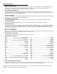
General Information 1. MACHINE IDENTIFICATION Machines are identified by model & in some cases a combination of model, serial number (S/N) or regional standard (CE, AUS, ANSI). Components may also be identified by S/N or manufacturer. Common components that may be identified by these characteristics are attachments, engine, transmission & hydraulic components. 2. PARTS MANUAL ORGANIZATION Product information in this manual is organized under section titles.
2 1 7 1 6 9 7 8 9 3
This Page Intentionally Left Blank 4
TABLE OF CONTENTS FIGURE NO. TITLE PAGE NO. SECTION 1 – FRAME & ATTACHING PARTS . . . . . . . . . . . . . . . . . . . . . . . . . . . . . . . . . . . . . . . . . . . . . . . . 1-1 1-1 1-2 Frame & Attaching Parts . . . . . . . . . . . . . . . . . . . . . . . . . . . . . . . . . . . . . . . . . . . . . . . . . . . . . . . 1-2 Covers . . . . . . . . . . . . . . . . . . . . . . . . . . . . . . . . . . . . . . . . . . . . . . . . . . . . . . . . . . . . . . . . . . . . . 1-4 SECTION 2 – BOOM . . . . . . . .
TABLE OF CONTENTS FIGURE NO. TITLE PAGE NO. SECTION 5 – DRIVE TRAIN . . . . . . . . . . . . . . . . . . . . . . . . . . . . . . . . . . . . . . . . . . . . . . . . . . . . . . . . . . . . . . . 5-1 5-1 5-2 5-3 5-4 5-5 5-6 5-7 5-8 5-9 5-10 5-11 5-12 5-13 5-14 5-15 5-16 5-17 5-18 5-19 5-20 5-21 5-22 5-23 5-24 5-25 5-26 5-27 5-28 5-29 5-30 5-31 5-32 5-33 Drive Train Components . . . . . . . . . . . . . . . . . . . . . . . . . . . . . . . . . . . . . . . . . . . . . . . . . . . . . . . Front Axle . . . . .
TABLE OF CONTENTS FIGURE NO. TITLE PAGE NO. SECTION 7 – CONTROLS . . . . . . . . . . . . . . . . . . . . . . . . . . . . . . . . . . . . . . . . . . . . . . . . . . . . . . . . . . . . . . . . 7-1 7-1 7-2 7-3 7-4 7-5 7-6 Brake . . . . . . . . . . . . . . . . . . . . . . . . . . . . . . . . . . . . . . . . . . . . . . . . . . . . . . . . . . . . . . . . . . . . . . Accelerator . . . . . . . . . . . . . . . . . . . . . . . . . . . . . . . . . . . . . . . . . . . . . . . . . . . . . . . . . . . . . . . . .
TABLE OF CONTENTS FIGURE NO. 10-4 10-5 10-6 10-7 10-8 10-9 10-10 10-11 TITLE PAGE NO. Road Lighting Installation . . . . . . . . . . . . . . . . . . . . . . . . . . . . . . . . . . . . . . . . . . . . . . . . . . . . . . . Work Lighting Installation . . . . . . . . . . . . . . . . . . . . . . . . . . . . . . . . . . . . . . . . . . . . . . . . . . . . . . . Rotating Beacon Installation . . . . . . . . . . . . . . . . . . . . . . . . . . . . . . . . . . . . . . . . . . . . . . . . . . . . Engine Harness .
SECTION 1 FRAME & ATTACHING PARTS 31200731 6036/6042
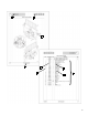
FRAME & ATTACHING PARTS Figure 1-1 Frame & Attaching Parts 14 17 21 28 13 31 10 18 22 23 1 2 12 6 36 144 7 133 30 29 1 3 8 12 36 35 11 27 PA4962 1-2 6036/6042 31200731
FRAME & ATTACHING PARTS Figure 1-1 Frame & Attaching Parts Item 1 2 3 6 7 8 9 10 11 12 13 14 15 16 17 18 19 20 21 22 23 24 27 28 29 30 31 35 36 133 144 31200731 Part Number Qty.
Before S/N 0160053077 FRAME & ATTACHING PARTS Figure 1-2 Covers 8 19 5 20 20 4 12 14 21 1 7 22 18 17 15 10 10 9 22 23 2 14 15 3 6 13 2 2 24 11 25 20 16 25 9 14 PA5500 16 24 1-4 6036/6042 31200731
Before S/N 0160053077 FRAME & ATTACHING PARTS Figure 1-2 Covers Item Part Number Qty.
S/N 0160053077 & After FRAME & ATTACHING PARTS Figure 1-2 Covers 1-6 6036/6042 31200731
S/N 0160053077 & After FRAME & ATTACHING PARTS Figure 1-2 Covers Item Part Number Qty.
FRAME & ATTACHING PARTS This Page Intentionally Left Blank 1-8 6036/6042 31200731
SECTION 2 BOOM 31200731 6036/6042
BOOM Figure 2-1 Boom Installation 6036 43 204 57 52 70 71 53 24 82 38 78 79 57 44 203 66 61 70 45 71 36 82 43 53 45 80 81 34 26 103 132 148 140 81 80 138 1 10 17 84 82 69 20 49 2 20 72 72 77 40 PA5530 2-2 6036/6042 31200731
BOOM Figure 2-1 Boom Installation Item Part Number Qty.
BOOM Figure 2-1 Boom Installation 6042 2-4 6036/6042 31200731
BOOM Figure 2-1 Boom Installation Item Part Number Qty.
BOOM Figure 2-2 First Boom Section 6036 44 55 51 63 63 68 68 9 14 16 9 22 19 16 50 2-6 5 85 68 63 100 PA5560 6036/6042 31200731
BOOM Figure 2-2 First Boom Section Item Part Number Qty. 5 9 14 16 19 22 44 50 51 55 63 68 85 100 5724622 7079572 7082311 7082362 7085442 7111572 7302056 8303679 8303681 8303738 8307005 8307204 8526007 3311601 1 6 18 6 2 2 1 6 8 4 18 18 AR 1 RUBBER BUMPER MOLDED WEAR PAD WEAR PAD INSERT WEAR PAD SHIM, 0.134 WEAR PAD SPACER, 0.88 HIGH CAPACITY WEAR PAD FIRST BOOM SECTION HEX HD CAPSCREW, 3/8-16X1.75, GR5 HEX HD CAPSCREW, 3/8-16X3/4, GR5 HEX HD CAPSCREW, 3/8-16X0.875, GR5 LOCKWASHER, 0.
BOOM Figure 2-2 First Boom Section 6042 38 50 87 68 72 10 11 57 87 8 9 68 72 10 11 8 9 21 20 68 9 50 21 49 87 2-8 7 51 87 87 102 19 PA5310 6036/6042 31200731
BOOM Figure 2-2 First Boom Section Item Part Number Qty. 7 8 9 10 11 19 20 21 38 49 50 51 57 68 72 87 102 5724622 7079572 7082311 7082342 7082362 7096772 7096882 7111572 7302052 8303041 8303620 8303621 8303681 8307005 8307204 8526007 3311601 1 6 21 AR AR 1 2 3 1 3 10 6 8 22 12 AR 1 RUBBER BUMPER MOLDED WEAR PAD WEAR PAD INSERT WEAR PAD SHIM, 0.075 WEAR PAD SHIM, 0.134 SPECIAL WEAR PAD SPACER WEAR PAD SPACER HIGH CAPACITY WEAR PAD FIRST SECTION BOOM HEX HD CAPSCREW, 3/8-16X1/2.
BOOM Figure 2-3 Second Boom Section 6036 14 22 10 48 68 63 63 55 68 51 63 68 10 9 19 14 50 16 63 19 9 15 9 14 14 68 22 14 63 9 16 2-10 50 63 51 68 55 PA5550 6036/6042 31200731
BOOM Figure 2-3 Second Boom Section Item Part Number Qty. 9 10 14 15 16 19 22 48 50 51 55 63 68 7079572 7080244 7082311 7082342 7082362 7085442 7111572 8303657 8303679 8303681 8303738 8307005 8307204 11 1 36 2 9 3 4 2 8 16 8 34 30 MOLDED WEAR PAD SECOND BOOM SECTION WEAR PAD INSERT WEAR PAD SHIM, 0.075 WEAR PAD SHIM, 0.134 WEAR PAD SPACER, 0.88 HIGH CAPACITY WEAR PAD HEX HD CAPSCREW, 3/8-16X2.00, GR5 HEX HD CAPSCREW, 3/8-16X1.75, GR5 HEX HD CAPSCREW, 3/8-16X3/4, GR5 HEX HD CAPSCREW, 3/8-16X0.
BOOM Figure 2-3 Second Boom Section 6042 9 72 68 50 57 21 10 11 68 72 8 9 51 68 72 18 51 57 68 8 10 11 68 8 9 72 10 11 24 10 11 18 8 9 21 68 51 20 2-12 PA5320 6036/6042 31200731
BOOM Figure 2-3 Second Boom Section Item Part Number Qty. 8 9 10 11 18 20 21 24 50 51 57 68 72 87 7079572 7082311 7082342 7082362 7096702 7096882 7111572 1001098089 8303620 8303621 8303681 8307005 8307204 8526007 11 36 AR AR 3 2 5 1 8 12 14 36 32 AR MOLDED WEAR PAD WEAR PAD INSERT WEAR PAD SHIM, 0.075 WEAR PAD SHIM, 0.
BOOM Figure 2-4 Third Boom Section 6036 14 22 21 19 50 55 63 51 63 68 14 26 16 9 9 14 PA5540 2-14 6036/6042 31200731
BOOM Figure 2-4 Third Boom Section Item Part Number Qty. 9 14 16 19 21 22 26 50 51 55 63 68 7079572 7082311 7082362 7085442 7096491 7111572 7117094 8303679 8303681 8303738 8307005 8307204 5 18 4 2 6 2 1 6 8 2 16 14 MOLDED WEAR PAD WEAR PAD INSERT WEAR PAD SHIM, 0.134 WEAR PAD SPACER, 0.88 WEAR PAD SCREW SPACER HIGH CAPACITY WEAR PAD THIRD BOOM SECTION HEX HD CAPSCREW, 3/8-16X1.75, GR5 HEX HD CAPSCREW, 3/8-16X3/4, GR5 HEX HD CAPSCREW, 3/8-16X0.875, GR5 LOCKWASHER, 0.
BOOM Figure 2-4 Third Boom Section 6042 9 68 21 10 11 56 20 55 27 68 57 68 72 10 11 8 18 9 8 10 11 9 PA5330 2-16 6036/6042 31200731
BOOM Figure 2-4 Third Boom Section Item Part Number Qty. 8 9 10 11 18 20 21 27 55 56 57 68 72 87 7079572 7082311 7082342 7082362 7096702 7096882 7111572 7117113 8303675 8303679 8303681 8307005 8307204 8526007 5 16 AR AR 1 2 2 1 2 6 8 16 8 AR MOLDED WEAR PAD WEAR PAD INSERT WEAR PAD SHIM, 0.075 WEAR PAD SHIM, 0.
BOOM Figure 2-5 Quick Attach Assembly 37 104 106 29 86 201 105 203 107 102 202 204 101 103 PA3811 2-18 6036/6042 31200731
BOOM Figure 2-5 Quick Attach Assembly Item Part Number Qty.
BOOM Figure 2-6 Boom Extend Chains 6036 6042 2-20 6036/6042 31200731
BOOM Figure 2-6 Boom Extend Chains Item Part Number Qty.
BOOM Figure 2-7 Boom Retract Chain 74 84 33 25 25 59 101 102 103 104 105 106 31 201 202 83 30 64 47 33 60 2-22 65 84 6036/6042 101 102 103 104 105 106 PA5510 31200731
BOOM Figure 2-7 Boom Retract Chain Item Part Number Qty.
BOOM This Page Intentionally Left Blank 2-24 6036/6042 31200731
SECTION 3 ATTACHMENTS 31200731 6036/6042
ATTACHMENTS Figure 3-1 Tilt Carriage 6 2 4 1 5 3 PY0431 3-2 6036/6042 31200731
ATTACHMENTS Figure 3-1 Tilt Carriage Item 1 2 3 4 5 6 31200731 Part Number Qty. 1170021 1170024 1001132514 0642032 NSS 3300240 3423275 3423242 3423276 90200003 NSS 1 1 1 2 1 2 1 1 1 2 1 Description 50 IN TILT CARRIAGE, (includes items 1 thru 6) 60 IN TILT CARRIAGE, (includes items 1 thru 6) 72 IN TILT CARRIAGE, (includes items 1 thru 6) HEX HD CAPSCREW, 5/8-11X4, GR5 TILT CARRIAGE LOCKNUT, 5/8-11 50 IN FORK PIN 60 IN FORK PIN 72 IN FORK PIN COLLAR S/N PLATE 6036/6042 Rev.
ATTACHMENTS Figure 3-2 Side Tilt Carriage 5 6 2 16 3 15 18 11 10 23 27 8 9 19 9 20 7 4 28 29 31 26 24 30 14 25 21 22 3 17 26 1 21 22 1 3-4 6036/6042 PAP2971 31200731
ATTACHMENTS Figure 3-2 Side Tilt Carriage Item 1 2 3 4 5 6 7 8 9 10 11 14 15 16 17 18 19 20 21 22 23 24 25 26 27 28 29 30 31 31200731 Part Number Qty.
ATTACHMENTS Figure 3-3 50 in Side Shift Carriage 11 18 12 1 7 15 12 12 10 3 6 11 12 16 19 10 11 7 16 17 11 7 2 18 3 19 24 26 25 22 5 26 23 4 5 5 14 21 8 4 9 13 20 20 10 13 11 10 21 5 21 14 11 13 PV2031 3-6 6036/6042 20 31200731
ATTACHMENTS Figure 3-3 50 in Side Shift Carriage Item 1 2 3 4 5 6 7 8 9 10 11 12 13 14 15 16 17 18 19 20 21 22 23 24 25 26 K1 K2 31200731 Part Number Qty. 1001142790 NSS 70024535 70024536 70024123 70024537 NSS 70024538 NSS 70024540 70024541 70024542 70024543 70024544 NSS 70024551 70024552 70024553 70024554 70022997 70024555 91403413 8420055 91403414 8420053 70024550 1 1 1 2 2 2 1 3 1 Ref 4 8 4 4 2 1 4 4 2 2 8 8 1 1 1 1 2 70024545 70024546 1 1 Description Rev.
ATTACHMENTS Figure 3-4 50 Inch Dual Fork Carriage 116 119 121 102 135 134 120 131 130 117 202 203 104 106 132 201 2 202 118 121 202 133 102 120 202 106 114 104 127 101 120 114 109 128 3 113 108 115 1 PH5130 3-8 6036/6042 31200731
ATTACHMENTS Figure 3-4 50 Inch Dual Fork Carriage Item Part Number Qty.
ATTACHMENTS Figure 3-5 90 Degree Swing Carriage 27 17 12 21 22 21 14 18 20 18 20 18 20 14 17 27 28 36 5 1 11 11 6 35 2 31 37 3 4 26 33 3 4 25 34 30 19 38 18 32 6 7 20 28 13 29 24 23 29 1 6 1 11 2 11 5 PH5140 3-10 6036/6042 31200731
ATTACHMENTS Figure 3-5 90 Degree Swing Carriage Item 1 2 3 4 5 6 7 11 12 13 14 17 18 19 20 21 22 23 24 25 26 27 28 29 30 31 32 33 34 35 36 37 38 31200731 Part Number Qty.
ATTACHMENTS Figure 3-6 Sheet Material Handler 1 2 3 4 7 5 107 6 106 101 102 103 104 105 PY1510 3-12 6036/6042 31200731
ATTACHMENTS Figure 3-6 Sheet Material Handler Item 1 2 3 4 5 6 7 101 102 103 104 105 106 107 31200731 Part Number Qty.
ATTACHMENTS Figure 3-7 Forks PV1550 3-14 6036/6042 31200731
ATTACHMENTS Figure 3-7 Forks Item Part Number Qty. 2340037 2340045 2340038 2340039 2340046 1001092391 1001137512 6 2 2 2 2 2 2 N1 Note Ref N2 Note Ref 31200731 Description CUBING FORK, 48X2X2, 11,640 LB PALLET FORK, 48X4X2.36, 10,950 LB PALLET FORK, 48X5X2.36, 13,700 LB DUAL TAPER FORK, 60X6X2.36, 16,300 LB DUAL TAPER FORK, 60X7X1.75, 10,800 LB DUAL TAPER FORK, 72X6X2, 11,300 LB FORK EXTENSION, 90” Rev.
ATTACHMENTS Figure 3-8 Fork Mounted Platform 111 115 6 4 102 3 5 107 106 8 105 105 104 105 7 2 116 1 110 112 103 117 101 109 114 108 113 118 PY1640 3-16 6036/6042 31200731
ATTACHMENTS Figure 3-8 Fork Mounted Platform Item 1 2 3 4 5 6 7 8 101 102 103 104 105 106 107 108 109 110 111 112 113 114 115 116 117 118 31200731 Part Number Qty.
ATTACHMENTS Figure 3-9 Lifting Hook NOTE: PALLET/LUMBER FORKS OF AN APPROPRIATE LOAD RATING MUST BE USED.
ATTACHMENTS Figure 3-9 Lifting Hook Item Part Number Qty. 1 2 3 4 5 6 7 91565094 7029520 90554080 7029521 70020555 1001093171 NSS 1 2 1 1 1 2 1 31200731 Description LIFTING HOOK, (includes all items) HAIRPIN CLIP SLING HOOK CHAIN SHACKLE ASSY, 12,000 LB, (includes pin) SPRING BUSHING PIN S/N PLATE 6036/6042 Rev.
ATTACHMENTS Figure 3-10 Fork Pin Lock Installation 1 4 2 5 3 PY1651 3-20 6036/6042 31200731
ATTACHMENTS Figure 3-10 Fork Pin Lock Installation Item Part Number Qty. 1 2 3 4 5 1001093465 0240156 1001093273 1001093377 1001094830 1001094330 1 1 1 2 4 2 31200731 Description FORK PIN LOCK INSTALLATION, (includes all items) LH FORK PIN LOCK RH FORK PIN LOCK HITCH PIN CLAMP LANYARD 6036/6042 Rev.
ATTACHMENTS Figure 3-11 Buckets 1 2 PH4370 3-22 6036/6042 31200731
ATTACHMENTS Figure 3-11 Buckets Item Part Number Qty. 1 1001100822 1001100823 1001100824 NSS 1 1 1 1 2 31200731 Description 72 IN BUCKET, 1.0 YD³, (includes item 2) 96 IN BUCKET, 1.5 YD³, (includes item 2) 102 IN BUCKET, 2.0 YD³, (includes item 2) S/N PLATE 6036/6042 Rev.
ATTACHMENTS Figure 3-12 Grapple Bucket 3-24 6036/6042 31200731
ATTACHMENTS Figure 3-12 Grapple Bucket Item 1 2 3 4 5 6 7 8 9 10 11 12 13 Part Number Qty.
ATTACHMENTS Figure 3-13 Truss Boom 2 3 PY1540 1 3-26 6036/6042 31200731
ATTACHMENTS Figure 3-13 Truss Boom Item Part Number Qty. 1 2 3 1001099902 1001099901 4110422 NSS NSS 1 1 2 1 1 31200731 Description 12 FT TRUSS BOOM, (includes all items) 15 FT TRUSS BOOM, (includes all items) WARNING SWINGING LOADS DECAL S/N PLATE TRUSS BOOM 6036/6042 Rev.
ATTACHMENTS Figure 3-14 12 Foot Truss Boom with Winch 1 2 2 22 3 4 7 8 25 5 23 6 8 24 9 10 22 12 11 21 13 20 19 17 16 18 15 PAP3441 3-28 6036/6042 31200731
ATTACHMENTS Figure 3-14 12 Foot Truss Boom with Winch Item 1 2 3 4 5 6 7 8 9 10 11 12 13 15 16 17 18 19 20 21 22 23 24 25 31200731 Part Number Qty.
ATTACHMENTS Figure 3-15 8 Foot Mast 3 4 26 13 25 14 8 7 2 5 15 10 9 18 1 19 20 16 17 21 24 22 23 101 6 275 PSI 12 11 K1 K2 K3 K4 K5 43 45 46 47 3-30 PAP4080 6036/6042 31200731
ATTACHMENTS Figure 3-15 8 Foot Mast (Continued) 27 28 40 30 29 39 41 31 37 40 38 35 32 64 39 33 34 65 36 38 37 63 66 27 33 28 34 27 28 48 58 48 54 48 55 56 61 44 51 59 52 53 49 31200731 6036/6042 60 62 PAP3740 50 3-31
ATTACHMENTS Figure 3-15 8 Foot Mast Item 1 2 3 4 5 6 7 8 9 10 11 12 13 14 15 16 17 18 19 20 21 22 23 24 25 26 27 28 29 30 31 32 33 34 35 36 37 38 39 40 41 43 44 45 46 47 48 3-32 Part Number Qty.
ATTACHMENTS Figure 3-15 8 Foot Mast (Continued) Item Part Number Qty. 49 50 51 52 53 54 55 56 58 59 60 61 62 63 64 65 66 101 70022936 70022937 70022949 70022950 70022942 70022952 91403414 91043126 70022939 91403413 91043125 70022935 70022946 70022949 70022980 70022998 70022990 NSS 1 1 2 2 1 1 1 1 1 1 1 1 1 4 2 4 1 1 K1 K2 70023925 70023005 1 1 K3 K4 K5 70023006 70023007 70023015 1 1 1 31200731 Description Rev.
ATTACHMENTS This Page Intentionally Left Blank 3-34 6036/6042 31200731
SECTION 4 ENGINE & ATTACHING PARTS 31200731 6036/6042
ENGINE & ATTACHING PARTS Figure 4-1 Engine Installation IF EQUIPPED FOR ULS 1 6 2 303 510 709 205 302 301 203 8 202 204 21 12 10 13 201 204 20 2 8 107 103 101 104 19 611 102 105 10 13 1 6 12 15 106 1 4 7 7 16 14 18 1 5 407 17 11 9 3 4-2 PA5120 6036/6042 31200731
ENGINE & ATTACHING PARTS Figure 4-1 Engine Installation Item Part Number Qty.
ENGINE & ATTACHING PARTS Figure 4-1 Engine Installation (Continued) Item 709 4-4 Part Number Qty. Ref Description Rev.
ENGINE & ATTACHING PARTS Figure 4-1 Engine Installation (Continued) Item 31200731 Part Number Qty. Description 6036/6042 Rev.
ENGINE & ATTACHING PARTS Figure 4-1 Engine Installation IF EQUIPPED FOR LS 509 2 1 5 608 20 8 407 708 202 204 203 6 7 302 303 301 16 12 10 201 204 13 205 104 19 22 102 103 2 21 8 101 15 17 12 1 5 10 13 7 14 1 4 18 11 9 3 4-6 PA5380 6036/6042 31200731
ENGINE & ATTACHING PARTS Figure 4-1 Engine Installation Item 1 2 3 4 5 6 7 8 9 10 11 12 13 14 15 16 17 18 19 20 21 22 101 102 103 104 201 202 203 204 205 301 302 303 407 509 608 708 31200731 Part Number Qty. Description Rev.
ENGINE & ATTACHING PARTS Figure 4-2 Engine IF EQUIPPED FOR ULS K1 K2 PAP26060 4-8 6036/6042 31200731
ENGINE & ATTACHING PARTS Figure 4-2 Engine Item K1 K2 31200731 Part Number Qty. Description 1001121252 70024274 70024275 70024276 70024277 70024278 70024279 70024280 70022842 70024281 70023812 70022846 70022844 70024284 1 1 1 1 1 1 1 1 1 1 1 1 1 1 ENGINE, QSB 3.
ENGINE & ATTACHING PARTS Figure 4-2 Engine IF EQUIPPED FOR LS K1 K2 PAP26070 4-10 6036/6042 31200731
ENGINE & ATTACHING PARTS Figure 4-2 Engine Item K1 K2 31200731 Part Number Qty. Description 1001131344 70024285 70021849 70021850 8036204 70021584 70023565 70022842 70024286 70022846 70022844 70024156 1 1 1 1 1 1 1 1 1 1 1 1 ENGINE, QSB 3.
ENGINE & ATTACHING PARTS Figure 4-3 Fuel System IF EQUIPPED FOR ULS 201 13 5 15 18 21 17 20 22 5 20 17 15 19 5 14 8 5 13 9 12 5 14 10 101 5 10 1 2 9 8 5 11 301 5 12 20 PH5470 4-12 6036/6042 31200731
ENGINE & ATTACHING PARTS Figure 4-3 Fuel System Item 1 2 5 8 9 10 11 12 13 14 15 17 18 19 20 21 22 101 201 301 31200731 Part Number Qty. Description Rev.
ENGINE & ATTACHING PARTS Figure 4-3 Fuel System IF EQUIPPED FOR LS 301 7 8 12 7 12 3 201 12 10 2 8 1 6 11 4 12 6 2 9 4 1 101 102 103 107 104 8 11 105 12 106 PH5870 12 4-14 105 108 6036/6042 31200731
ENGINE & ATTACHING PARTS Figure 4-3 Fuel System Item Part Number Qty. Description Rev.
ENGINE & ATTACHING PARTS Figure 4-4 Radiator & Oil Cooler Mounting IF EQUIPPED FOR ULS 4-16 6036/6042 31200731
ENGINE & ATTACHING PARTS Figure 4-4 Radiator & Oil Cooler Mounting Item 1 2 3 4 5 6 7 8 10 11 12 14 15 16 17 18 19 20 21 22 23 24 25 26 101 102 103 104 105 106 107 108 110 111 112 114 115 116 117 118 31200731 Part Number Qty.
ENGINE & ATTACHING PARTS Figure 4-4 Radiator & Oil Cooler Mounting (Continued) Item Part Number Qty. 201 202 203 204 205 207 208 213 301 70024148 70024149 70024150 70024151 70024530 70025541 70025542 70025540 8420213 1 1 1 1 1 8 1 19 1 4-18 Description Rev.
ENGINE & ATTACHING PARTS Figure 4-4 Radiator & Oil Cooler Mounting (Continued) Item 31200731 Part Number Qty. Description 6036/6042 Rev.
ENGINE & ATTACHING PARTS Figure 4-4 Radiator & Oil Cooler Mounting IF EQUIPPED FOR LS 203 205 203 210 203 102 203 208 205 19 203 11 7 6 18 204 9 209 23 10 24 22 104 8 1 20 6 203 21 19 206 208 7 201 105 6 9 1 204 21 201 8 20 8 12 17 9 6 10 16 5 2 21 103 101 19 13 8 12 9 202 15 202 21 207 5 14 2 19 PA5390 4-20 6036/6042 31200731
ENGINE & ATTACHING PARTS Figure 4-4 Radiator & Oil Cooler Mounting Item 1 2 5 6 7 8 9 10 11 12 13 14 15 16 17 18 19 20 21 22 23 24 101 102 103 104 105 201 202 203 204 205 206 207 208 209 210 31200731 Part Number Qty.
ENGINE & ATTACHING PARTS Figure 4-5 Air Cleaner Assembly IF EQUIPPED FOR ULS 14 6 9 6 11 6 10 8 7 104 105 103 102 13 101 103 12 3 1 2 4-22 6036/6042 5 1 4 PA5090 31200731
ENGINE & ATTACHING PARTS Figure 4-5 Air Cleaner Assembly Item 1 2 3 4 5 6 7 8 9 10 11 12 13 14 15 16 17 18 19 101 102 103 104 105 31200731 Part Number Qty.
ENGINE & ATTACHING PARTS Figure 4-5 Air Cleaner Assembly IF EQUIPPED FOR LS 13 4 5 2 10 3 101 1 103 6 102 12 104 8 7 105 9 4-24 6036/6042 11 PH5900 31200731
ENGINE & ATTACHING PARTS Figure 4-5 Air Cleaner Assembly Item 1 2 3 4 5 6 7 8 9 10 11 12 13 101 102 103 104 105 31200731 Part Number Qty.
ENGINE & ATTACHING PARTS Figure 4-6 Exhaust System IF EQUIPPED FOR ULS 15 9 7 7 8 6 7 13 10 12 7 4 1 2 11 3 4-26 6036/6042 1 14 PA5081 31200731
ENGINE & ATTACHING PARTS Figure 4-6 Exhaust System Item 1 2 3 4 5 6 7 8 9 10 11 12 13 14 15 31200731 Part Number Qty.
ENGINE & ATTACHING PARTS Figure 4-6 Exhaust System IF EQUIPPED FOR LS 8 6 6 10 13 11 6 7 6 9 12 104 103 1 14 101 102 103 101 102 4-28 1 2 3 PH5910 6036/6042 31200731
ENGINE & ATTACHING PARTS Figure 4-6 Exhaust System Item 1 2 3 6 7 8 9 10 11 12 13 14 122 101 102 103 104 31200731 Part Number Qty. 1001131485 Ref 0100011 0641508 4891500 83683175 1001127858 1001131576 1001131577 1001131578 1001131772 1001131996 1001132154 0791718 1001132004 AR 5 5 4 1 1 1 1 1 1 1 4 1 1001127864 Ref 0100011 0641607 4891600 1001127867 AR 4 4 1 Description Rev.
ENGINE & ATTACHING PARTS Figure 4-7 Isolation Coupler 9 8 6 2 1 7 4 3 K1 5 4-30 PA4271 6036/6042 31200731
ENGINE & ATTACHING PARTS Figure 4-7 Isolation Coupler Item Part Number Qty.
ENGINE & ATTACHING PARTS This Page Intentionally Left Blank 4-32 6036/6042 31200731
SECTION 5 DRIVE TRAIN 31200731 6036/6042
DRIVE TRAIN Figure 5-1 Drive Train Components 3 5 3 5 202 204 113 112 116 110 6 107 117 109 5 4 115 201 111 114 108 2 105 102 106 104 103 211 210 212 114 209 1 115 101 106 203 K1 K2 105 6 104 205 103 206 207 208 5 4 PA4321 5-2 6036/6042 31200731
DRIVE TRAIN Figure 5-1 Drive Train Components Item Part Number Qty.
DRIVE TRAIN Figure 5-1 Drive Train Components (Continued) 5-4 Item Part Number Qty. Description 212 8630019 1 O-RING K1 K2 8880218-OM 8880219-OM 4 1 STRAP KIT, (includes qty. 2 of item 114 & qty. 4 of item 115) STRAP KIT, (includes qty. 2 of item 116 & qty. 4 of item 117) 6036/6042 Rev.
DRIVE TRAIN Figure 5-1 Drive Train Components (Continued) Item 31200731 Part Number Qty. Description 6036/6042 Rev.
DRIVE TRAIN Figure 5-2 Front Axle 5-6 6036/6042 31200731
DRIVE TRAIN Figure 5-2 Front Axle Item Part Number Qty. 1 1001103625 1 Ref Ref Ref Ref Ref Ref Ref 31200731 Description FRONT AXLE, (includes all items) INPUT, (see Figure 5-3 for details) LIMITED SLIP DIFFERENTIAL, (see Figure 5-4 for details) AXLE CASING, (see Figure 5-5 for details) M-DISK BRAKE, (see Figure 5-6 for details) BRAKE, (see Figure 5-7 for details) JOINT HOUSING, (see Figure 5-8 for details) PLANETARY DRIVE, (see Figure 5-9 for details) 6036/6042 Rev.
DRIVE TRAIN Figure 5-3 Front Axle - Input 1 1 3 2 4 5 6 7 10 8 9 PA4760 5-8 6036/6042 31200731
DRIVE TRAIN Figure 5-3 Front Axle - Input Item Part Number Qty.
DRIVE TRAIN Figure 5-3 Front Axle - Input (Continued) Item Part Number Qty. 5 6 7 8 9 10 80304104 80304121 80304122 80304097 80304123 80304125 80304107 80304126 80304127 80304108 80304128 80304129 80304099 80304130 80304131 80304132 80304133 80304100 80304134 80304135 80304136 80304137 80304101 80304102 1319353 70022220 70022245 80304082 70022213 70022776 1 1 1 1 1 1 1 1 1 1 1 1 1 1 1 1 1 1 1 1 1 1 1 1 1 1 1 1 1 1 5-10 Description Rev. RING, S=16.86 RING, S=16.88 RING, S=16.9 RING, S=16.
DRIVE TRAIN Figure 5-3 Front Axle - Input (Continued) Item 31200731 Part Number Qty. Description 6036/6042 Rev.
DRIVE TRAIN Figure 5-4 Front Axle - Limited Slip Differential 7 7 6 6 5 8 5 3 9 4 10 9 1 10 6 6 7 7 2 12 13 11 3 4 2 PA3301 5-12 6036/6042 31200731
DRIVE TRAIN Figure 5-4 Front Axle - Limited Slip Differential Item Part Number Qty. 1 2 70022226 70022263 70022264 70022260 70022261 70022225 70022185 70022262 70022227 70022228 70022200 70022229 1 AR AR 8 2 2 4 4 1 2 2 1 Ref 16 3 4 5 6 7 8 9 10 11 12 13 31200731 70022211 Description Rev. DIFFERENTIAL CASE O.CLUTCH DISC, A=1.2 O.CLUTCH DISC, A=1.3 I.
DRIVE TRAIN Figure 5-5 Front Axle - Casing 107 105 103 106 102 103 106 27 104 106 26 25 20 7 8 23 6 5 24 15 22 13 21 17 18 12 16 4 14 1 16 12 14 25 22 13 24 101 23 19 2 15 9 10 1 3 8 7 6 5-14 21 5 PA3312 6036/6042 31200731
DRIVE TRAIN Figure 5-5 Front Axle - Casing Item Part Number Qty.
DRIVE TRAIN Figure 5-6 Front Axle - M-Disk Brake 21 4 5 23 24 1 3 2 14 6 12 11 20 19 13 8 7 9 16 10 15 17 5 20 18 PA3321 5-16 6036/6042 31200731
DRIVE TRAIN Figure 5-6 Front Axle - M-Disk Brake Item Part Number Qty. 1 2 3 4 5 6 7 8 9 10 11 12 13 14 15 16 17 18 19 20 21 22 23 24 70022778 1319578 70022209 70022779 80304462 70022250 70022190 70022193 70022189 70022194 70022236 70022183 70022198 70022235 70022186 1319214 70022196 70022176 70022253 10731949 70022171 70022780 8036447 1319537 1319545 1319539 1319540 1319542 2 2 6 10 4 2 2 2 2 2 2 2 2 2 2 6 8 6 2 4 2 2 2 2 2 2 2 2 31200731 Description Rev.
DRIVE TRAIN Figure 5-7 Front Axle - Brake 10 4 5 3 6 8 1 9 2 PA3331 5-18 6036/6042 31200731
DRIVE TRAIN Figure 5-7 Front Axle - Brake Item Part Number Qty. Description 1 2 3 4 5 6 7 8 9 10 70022199 70022252 70022251 70022191 70022192 70022195 70022780 70022248 70022202 2 2 2 2 2 2 2 14 14 Ref SNAP RING WASHER PISTON PISTON PACKING ROD SEAL CUP SPRING SCREW PLUG, (not shown) PRESSURE PIN O-RING BRAKE HOUSING, (see Figure 5-6 for details) 31200731 6036/6042 Rev.
DRIVE TRAIN Figure 5-8 Front Axle - Joint Housing 11 12 13 4 14 12 3 15 8 3 6 4 5 19 18 27 10 7 9 25 1 2 25 26 5 6 24 23 21 20 22 16 17 17 PA3341 5-20 6036/6042 31200731
DRIVE TRAIN Figure 5-8 Front Axle - Joint Housing Item Part Number Qty. 1 2 3 4 5 6 7 8 9 10 11 12 13 14 15 16 17 18 19 20 21 22 23 24 25 26 27 70022237 70022238 70022223 1319447 70022240 1319464 70022179 10731789 70022218 1321226 70022781 70021554 70022782 70022187 70022188 80304173 1319472 70022783 70022234 70022249 70022203 70022230 1 1 4 4 4 16 2 2 2 2 2 2 1 1 1 2 4 16 16 2 2 20 Ref Ref 4 2 2 31200731 8036330 70022257 1319477 Description Rev.
DRIVE TRAIN Figure 5-9 Front Axle - Planetary Drive 2 9 4 10 1 5 8 6 7 3 PA3351 5-22 6036/6042 31200731
DRIVE TRAIN Figure 5-9 Front Axle - Planetary Drive Item Part Number Qty. 1 2 3 4 5 6 7 8 9 10 70022242 70022784 70022233 70022256 70022243 70022785 70022197 1319578 70022207 1 2 2 1 3 3 3 2 4 Ref 31200731 Description Rev.
DRIVE TRAIN Figure 5-10 Rear Axle 6036 6042 5-24 6036/6042 31200731
DRIVE TRAIN Figure 5-10 Rear Axle Item Part Number Qty. 1 2 1001106727 1001103630 1 1 Ref Ref Ref Ref Ref Ref 31200731 Description REAR AXLE, (6036), (includes all items) REAR AXLE, (6042), (includes all items) INPUT, (see Figure 5-11 for details) LIMITED SLIP DIFFERENTIAL, (see Figure 5-12 for details) AXLE CASING, (see Figure 5-13 for details) M-DISK BRAKE, (see Figure 5-14 for details) JOINT HOUSING, (see Figure 5-15 for details) PLANETARY DRIVE, (see Figure 5-16 for details) 6036/6042 Rev.
DRIVE TRAIN Figure 5-11 Rear Axle - Input 9 8 7 10 6 5 4 2 3 1 PA4770 5-26 6036/6042 31200731
DRIVE TRAIN Figure 5-11 Rear Axle - Input Item Part Number Qty.
DRIVE TRAIN Figure 5-11 Rear Axle - Input (Continued) Item Part Number Qty. 5 6 7 8 9 10 80304110 80304111 80304112 80304113 80304114 80304115 80304117 80304118 80304119 80304120 80304121 80304122 80304123 80304124 80304125 80304126 80304127 80304128 80304129 80304130 80304131 80304132 80304133 80304134 80304135 80304136 80304137 1319353 70022220 70022245 80304082 70022213 70022244 1 1 1 1 1 1 1 1 1 1 1 1 1 1 1 1 1 1 1 1 1 1 1 1 1 1 1 1 1 1 1 1 1 5-28 Description Rev. RING, S=16.56 RING, S=16.
DRIVE TRAIN Figure 5-11 Rear Axle - Input (Continued) Item 31200731 Part Number Qty. Description 6036/6042 Rev.
DRIVE TRAIN Figure 5-12 Rear Axle - Differential 7 2 6 7 6 4 9 3 5 10 1 3 4 5 8 11 9 10 6 7 6 7 PA4700 5-30 6036/6042 31200731
DRIVE TRAIN Figure 5-12 Rear Axle - Differential Item Part Number Qty. 1 2 3 4 5 6 7 8 9 10 11 70022229 70023910 70022284 70022285 70022225 70022185 70022262 70022227 70022228 70023904 70022211 1 1 2 2 2 4 4 1 2 2 16 31200731 Description Rev. COVER DIFFERENTIAL CASE THRUST WASHER DIFFERENTIAL RING, A=15.
DRIVE TRAIN Figure 5-13 Rear Axle - Casing 104 106 103 106 102 103 106 12 105 13 25 107 15 16 20 14 7 23 101 8 24 5 6 22 21 12 16 13 1 14 17 18 4 22 25 24 23 19 2 15 27 9 10 1 3 26 21 8 7 6 5 PA3382 5-32 6036/6042 31200731
DRIVE TRAIN Figure 5-13 Rear Axle - Casing Item Part Number Qty.
DRIVE TRAIN Figure 5-14 Rear Axle - M-Disk Brake 21 4 5 23 24 1 3 2 14 6 12 11 20 19 13 8 7 9 16 10 15 17 5 20 18 PA3321 5-34 6036/6042 31200731
DRIVE TRAIN Figure 5-14 Rear Axle - M-Disk Brake Item Part Number Qty. 1 70022788 70022282 1319578 70022209 70022779 8036847 80304462 70022250 70022190 70022193 70022189 70022194 70022236 70022183 70022198 70022235 70022186 1319214 70022196 70022176 70022253 10731949 70022171 70022280 70022215 8036447 1319537 1319545 1319539 1319540 1319542 2 2 2 6 10 10 4 2 2 2 2 2 2 2 2 2 8 6 8 6 2 4 2 2 2 2 AR AR AR AR AR 2 3 4 5 6 7 8 9 10 11 12 13 14 15 16 17 18 19 20 21 22 23 24 31200731 Description Rev.
DRIVE TRAIN Figure 5-15 Rear Axle - Joint Housing 11 12 13 4 14 12 3 15 8 3 6 4 5 19 18 27 10 7 9 25 1 2 25 26 5 6 24 23 21 20 22 16 17 17 PA3341 5-36 6036/6042 31200731
DRIVE TRAIN Figure 5-15 Rear Axle - Joint Housing Item Part Number Qty. 1 2 3 4 5 6 7 8 9 10 11 70022237 70022238 70022223 1319447 70022240 1319464 70022179 10731789 70022218 1321226 70022781 1 1 4 4 4 16 2 2 2 2 2 70022170 2 70021554 70022782 70021553 70022187 70022188 80304173 1319472 70022783 70022208 70022234 70022249 70022203 70022230 2 1 1 1 1 2 4 16 16 16 2 2 20 Ref Ref 4 2 2 12 13 14 15 16 17 18 19 20 21 22 23 24 25 26 27 31200731 8036330 70022257 1319477 Description Rev.
DRIVE TRAIN Figure 5-16 Rear Axle - Planetary Drive 2 9 4 10 1 5 8 6 7 3 PA3351 5-38 6036/6042 31200731
DRIVE TRAIN Figure 5-16 Rear Axle - Planetary Drive Item Part Number Qty. 1 2 70022242 70022784 70022239 70022233 70022256 70022243 70022785 70022197 1319578 70022207 1 2 2 2 1 3 3 3 2 4 Ref 3 4 5 6 7 8 9 10 31200731 Description Rev.
DRIVE TRAIN Figure 5-17 ZF Transmission Installation 3 10 9 11 5 12 8 6 13 2 4 1 7 5 2 4 1 6 8 7 PH5380 5-40 6036/6042 31200731
DRIVE TRAIN Figure 5-17 ZF Transmission Installation Item 1 2 3 4 5 6 7 8 9 10 11 12 13 31200731 Part Number Qty. Description Rev.
DRIVE TRAIN Figure 5-18 ZF Transmission - Engine Connection & Converter 10 11 2 12 14 7 4 8 13 PH5360 9 5-42 1 5 6 15 3 6036/6042 31200731
DRIVE TRAIN Figure 5-18 ZF Transmission - Engine Connection & Converter Item Part Number Qty. 1 2 3 4 5 6 7 8 9 10 11 12 13 14 15 1319203 1319204 10732095 10731702 1319213 70023482 1319209 1319210 8036021 8036022 10731748 10731751 1319211 1319205 70023483 1 4 4 8 1 1 1 1 1 1 12 12 1 1 2 31200731 Description Rev. DIAPHRAGM HEX HD CAPSCREW, M10X18mm WASHER, 10.
DRIVE TRAIN Figure 5-19 ZF Transmission - Input Shafts 1 3 2 4 5 6 7 8 PA3130 5-44 6036/6042 31200731
DRIVE TRAIN Figure 5-19 ZF Transmission - Input Shafts Item Part Number Qty. 1 2 3 4 5 6 7 8 8036023 1319557 1319558 1319563 10731913 80304405 1319565 1319566 1 1 1 1 1 1 1 1 31200731 Description Rev. TURBINE SHAFT STATOR SHAFT BEARING BUSHING BALL BEARING SNAP RING RETAINING RING, 55X2.00 PISTON RING, 55X3.
DRIVE TRAIN Figure 5-20 ZF Transmission - Gearbox Housing 6 1 10 8 11 9 7 23 2 5 4 3 18 17 16 16 17 17 18 19 16 16 18 17 16 18 21 12 17 16 17 20 18 14 18 15 22 13 PA3140 5-46 6036/6042 31200731
DRIVE TRAIN Figure 5-20 ZF Transmission - Gearbox Housing Item Part Number Qty. 1 2 3 4 5 6 7 8 9 10 11 12 13 14 15 16 17 18 19 20 21 22 23 8036024 8036025 1319569 1319570 1319571 10731744 1319574 1319575 1319576 1319577 1319569 1319578 8036026 1319581 1319582 1319583 1319584 1319585 1319586 1319587 8036027 8036028 1319590 1 1 36 6 2 1 1 1 1 6 23 1 1 1 2 6 6 11 1 1 1 1 1 31200731 Description Rev.
DRIVE TRAIN Figure 5-21 ZF Transmission - Coupling Group 1 4 1 2 5 3 17 15 17 8 9 6 7 10 11 12 13 14 12 13 16 7 PA3150 5-48 6036/6042 31200731
DRIVE TRAIN Figure 5-21 ZF Transmission - Coupling Group 1 Item Part Number Qty. 1 2 3 4 5 6 7 8 9 10 11 1319591 1319592 1319593 1319594 1319595 1319596 10731845 7026758 7026759 7026760 1319600 1319601 1319602 1319603 1319604 1319605 1319606 1319607 1319608 1319609 1319610 1319611 1319612 1 1 1 1 5 1 2 12 12 1 1 1 1 1 1 2 2 1 1 1 1 1 2 12 13 14 15 16 17 31200731 Description Rev. COUPLING PISTON O-RING, 52X3.00 O-RING, 115X3.00 CUP SPRING SHIM, 2.00 RETAINING RING, 40X1.75 LIN.CLUTCH DISC O.
DRIVE TRAIN Figure 5-22 ZF Transmission - Coupling Group 2 1 4 2 3 17 15 17 9 6 7 5 8 14 10 11 7 12 13 16 12 13 PA3160 5-50 6036/6042 31200731
DRIVE TRAIN Figure 5-22 ZF Transmission - Coupling Group 2 Item Part Number Qty. 1 2 3 4 5 6 7 8 9 10 11 1319613 8036029 1319593 1319594 1319595 1319596 10731845 7026758 7026759 7026760 1319600 1319601 1319602 1319603 1319604 1319605 1319606 1319614 1319615 8036190 7029532 7029533 1319612 1 1 1 1 5 1 2 8 8 1 1 1 1 1 1 2 2 1 1 1 1 1 2 12 13 14 15 16 17 31200731 Description Rev. COUPLING PISTON O-RING, 52X3.00 O-RING, 115X3.00 CUP SPRING SHIM, 2.00 RETAINING RING, 40X1.75 LIN.CLUTCH DISC O.
DRIVE TRAIN Figure 5-23 ZF Transmission - Coupling Group 3 5 12 15 14 7 6 13 8 11 10 9 1 16 17 2 4 3 17 PA3170 5-52 6036/6042 31200731
DRIVE TRAIN Figure 5-23 ZF Transmission - Coupling Group 3 Item Part Number Qty. 1 2 3 4 5 6 7 8 9 10 11 1319616 8036029 1319593 1319594 1319595 1319617 1319618 7026758 7026759 7026760 1319600 1319601 1319602 1319603 1319604 1319619 1319620 1319621 1319622 1319623 1319624 1319625 1319626 1319627 1319628 1319629 1319630 1319631 1319632 8036190 7029532 7029533 1319633 1319612 1 1 1 1 5 1 1 8 8 1 1 1 1 1 1 1 1 1 1 1 1 1 1 1 1 1 1 1 1 1 1 1 1 2 12 13 14 15 16 17 31200731 Description Rev.
DRIVE TRAIN Figure 5-24 ZF Transmission - Coupling Group 4 4 1 2 3 17 15 17 8 6 5 7 9 10 12 13 11 14 12 13 16 7 PA3180 5-54 6036/6042 31200731
DRIVE TRAIN Figure 5-24 ZF Transmission - Coupling Group 4 Item Part Number Qty. 1 2 3 4 5 6 7 8 9 10 11 1319634 8036029 1319593 1319594 1319595 1319596 10731845 7026758 7026759 7026760 1319600 1319601 1319602 1319603 1319604 1319605 1319606 1319635 1319615 1319636 1319612 1 1 1 1 5 1 2 8 8 1 1 1 1 1 1 2 2 1 1 1 2 12 13 14 15 16 17 31200731 Description Rev. COUPLING PISTON O-RING O-RING CUP SPRING SHIM, 2.00 RETAINING RING LIN.CLUTCH DISC O.CLUTCH DISC END SHIM SNAP RING, 4.00 SNAP RING, 3.
DRIVE TRAIN Figure 5-25 ZF Transmission - Reversing Gear Group I 2 4 1 15 3 17 17 8 9 5 12 10 11 6 13 14 16 7 PA3190 5-56 6036/6042 31200731
DRIVE TRAIN Figure 5-25 ZF Transmission - Reversing Gear Group I Item Part Number Qty. 1 2 3 4 5 6 7 8 9 10 11 1319637 8036029 1319593 1319594 1319595 1319617 1319618 7026758 7026759 7026760 1319600 1319601 1319602 1319603 1319604 1319638 1319620 1319621 1319622 1319623 1319624 1319625 1319626 1319627 1319628 1319629 1319630 1319631 1319632 1319615 1319636 1319612 1 1 1 1 7 1 1 11 11 1 1 1 1 1 1 1 1 1 1 1 1 1 1 1 1 1 1 1 1 1 1 2 12 13 14 15 16 17 31200731 Description Rev.
DRIVE TRAIN Figure 5-26 ZF Transmission - Reversing Gear Group 2 2 4 1 15 3 17 17 9 5 8 12 10 11 6 13 14 16 7 PA3200 5-58 6036/6042 31200731
DRIVE TRAIN Figure 5-26 ZF Transmission - Reversing Gear Group 2 Item Part Number Qty. 1 2 3 4 5 6 7 8 9 10 11 1319639 8036029 1319593 1319594 1319595 1319617 1319618 7026758 7026759 7026760 1319600 1319601 1319602 1319603 1319604 1319638 1319620 1319621 1319622 1319623 1319624 1319625 1319626 1319627 1319628 1319629 1319630 1319631 1319632 1319608 1319636 1319612 1 1 1 1 7 1 1 11 11 1 1 1 1 1 1 1 1 1 1 1 1 1 1 1 1 1 1 1 1 1 1 2 12 13 14 15 16 17 31200731 Description Rev.
DRIVE TRAIN Figure 5-27 ZF Transmission - Output 2 9 11 8 10 12 3 14 15 13 4 7 5 6 1 3 2 8 9 10 11 12 PA3210 5-60 6036/6042 31200731
DRIVE TRAIN Figure 5-27 ZF Transmission - Output Item Part Number Qty. 1 2 3 4 8036030 1319641 7027273 NSS 70020430 70020431 1319643 8036031 1319646 1319647 10839156 1319648 1319649 10731959 8036032 1319633 8036190 7029532 7029533 1 2 2 1 1 1 1 1 5 2 2 2 2 4 1 1 1 1 1 5 6 7 8 9 10 11 12 13 14 15 31200731 Description Rev. OUTPUT SHAFT SHAFT SEAL OUTPUT FLANGE ROLLER BEARING ASSY CUP CONE ROLLER BEARING SCREEN SHEET HEX HD CAPSCREW, M6X10mm SCREEN SHEET O-RING WASHER 10.
DRIVE TRAIN Figure 5-28 ZF Transmission - Control Unit 11 7 8 6 2 1 9 6 10 8 12 5 3 5-62 4 6036/6042 31200731
DRIVE TRAIN Figure 5-28 ZF Transmission - Control Unit Item Part Number Qty. 1 2 3 4 5 6 7 8 9 10 11 12 1319650 8036033 10732072 10732071 1319652 1319661 70020425 7029037 1319659 70020426 1 1 1 1 1 19 1 19 43 1 Ref Ref 31200731 Description Rev. GASKET DUCT PLATE COMPRESSION SPRING BALL ORIFICE WASHER, 6.4 INTERM. SHEET HEX HD CAPSCREW, M6X60mm TORX SCREW, M8X30mm INTERM.
DRIVE TRAIN Figure 5-29 ZF Transmission - Valve Housing Assembly 38 37 39 40 41 20 20 36 34 35 30 30 33 31 29 23 6 4 15 33 31 21 27 26 25 24 22 13 33 28 32 16 7 32 31 30 32 5 1 3 2 14 8 9 11 10 17 12 20 18 19 PA3230 5-64 6036/6042 31200731
DRIVE TRAIN Figure 5-29 ZF Transmission - Valve Housing Assembly Item 1 2 3 4 5 6 7 8 9 10 11 12 13 14 15 16 17 18 19 20 21 22 23 24 25 26 27 28 29 30 31 32 33 34 35 36 37 38 39 40 31200731 Part Number Qty.
DRIVE TRAIN Figure 5-29 ZF Transmission - Valve Housing Assembly (Continued) Item Part Number Qty. 41 10731709 1 5-66 Description Rev. O-RING, 8X1.
DRIVE TRAIN Figure 5-29 ZF Transmission - Valve Housing Assembly (Continued) Item 31200731 Part Number Qty. Description 6036/6042 Rev.
DRIVE TRAIN Figure 5-30 ZF Transmission - Valve Block Assembly 11 12 10 9 4 4 4 5 2 5 6 5 6 6 2 2 3 3 3 1 14 13 8 7 PA3240 5-68 6036/6042 31200731
DRIVE TRAIN Figure 5-30 ZF Transmission - Valve Block Assembly Item Part Number Qty. 1 2 3 4 5 6 7 8 9 10 11 12 13 14 1319717 70020427 1319710 1319696 1319702 10732063 1319703 1319711 1319707 1319712 1319713 1319714 1319715 1319670 10731709 1 1 3 3 3 3 3 1 1 1 1 9 9 3 3 31200731 Description Rev.
DRIVE TRAIN Figure 5-31 ZF Transmission - Oil Pump & Filter 3 6 7 5 4 9 2 1 8 3 12 10 13 11 14 15 PA3250 5-70 6036/6042 31200731
DRIVE TRAIN Figure 5-31 ZF Transmission - Oil Pump & Filter Item Part Number Qty. 1 1319718 7029417 8036250 1319719 1319720 1319721 1319722 1319723 1319724 1319725 1319726 8036041 8036042 1319585 1319582 1319581 1 1 1 2 1 1 1 1 1 4 1 1 1 1 1 1 2 3 4 5 6 7 8 9 10 11 12 13 14 15 31200731 Description Rev.
DRIVE TRAIN Figure 5-32 Fender Installation 103 105 102 103 105 3 105 101 104 2 5 4 2 105 104 1 1 K1 PA4232 5-72 6036/6042 31200731
DRIVE TRAIN Figure 5-32 Fender Installation Item Part Number Qty.
DRIVE TRAIN Figure 5-33 Wheel Assembly PNEUMATIC 1 2 7 8 9 151 103 102 9 151 5-74 6036/6042 PA4781 31200731
DRIVE TRAIN Figure 5-33 Wheel Assembly Item 1 2 7 8 9 102 103 151 N1 31200731 Part Number Qty. Description 7138658 1 7138659 7138660 1 1 7138661 1 1001100324 8780031 8780036 7301054 7301056 8786514 1001100005 1001100284 1 1 1 1 1 1 1 1 Ref TIRE & RIM ASSY, (right side), 13.00X24, 12 PLY, G2, (includes items 1, 7 & 9) TIRE & RIM ASSY, (left side), 13.00X24, 12 PLY, (includes items 1, 7 & 9) TIRE & RIM ASSY, (right side), 15.
DRIVE TRAIN Figure 5-33 Wheel Assembly FOAM FILLED & SOLID 5-76 6036/6042 31200731
DRIVE TRAIN Figure 5-33 Wheel Assembly Item Part Number Qty. Description Rev. 7139159 1 D 7139160 1 7139161 1 7139162 1 4520319 1 4520648 1001151107 1001121085 1 1 1 1 2 3 7 8 9 10 11 12 13 14 15 102 103 8780031 8780036 8780045 7301054 7301056 8786514 4520649 4520650 1001151099 1001151100 1001100005 1001100284 1 1 1 1 1 1 1 1 2 2 Ref Ref 1 1 TIRE & RIM ASSY, (right side), FOAM FILLED, 13.00X24, 12 PLY, G-2, (includes items 1, 7 & 9) TIRE & RIM ASSY, (left side), FOAM FILLED, 13.
DRIVE TRAIN This Page Intentionally Left Blank 5-78 6036/6042 31200731
SECTION 6 CAB 31200731 6036/6042
CAB Figure 6-1 Cab Installation 14 17 15 16 13 12 10 11 18 19 26 1 2 1 2 23 22 25 24 21 8 3 9 7 20 6 4 6 5 5 PAP26000 6-2 6036/6042 31200731
CAB Figure 6-1 Cab Installation Item 1 2 3 4 5 6 7 8 9 10 11 12 13 14 15 16 17 18 19 20 21 22 23 24 25 26 31200731 Part Number Qty. Description Rev.
CAB Figure 6-2 Cab Assembly 6-4 6036/6042 31200731
CAB Figure 6-2 Cab Assembly Item 1 2 3 4 5 6 7 10 11 12 13 14 15 16 17 18 19 20 21 22 23 24 25 26 27 28 29 30 31 32 33 34 35 36 37 38 39 40 41 42 43 44 45 46 47 48 101 31200731 Part Number Qty.
CAB Figure 6-2 Cab Assembly (Continued) 6-6 Item Part Number Qty. 102 103 104 105 106 7302073 1001129610 7302076 7302077 8303034 1 1 1 1 20 K1 K2 8036199 8036198 1 1 Description Rev.
CAB Figure 6-2 Cab Assembly (Continued) Item 31200731 Part Number Qty. Description 6036/6042 Rev.
Before S/N 0160050424 CAB Figure 6-3 Cab Door Assembly 37 38 34 40 37 32 35 37 39 27 33 40 30 29 37 37 38 28 31 9 14 40 3 2 18 36 17 7 37 41 21 20 21 4 5 16 11 23 26 19 6 22 1 13 15 8 25 10 21 24 2 2 12 PH5970 6-8 6036/6042 31200731
Before S/N 0160050424 CAB Figure 6-3 Cab Door Assembly Item Part Number Qty.
S/N 0160050424 & After CAB Figure 6-3 Cab Door Assembly 214 221 202 1 311 302 305 314 312 202 308 313 306 307 301 214 221 2 203 314 310 305 203 203 221 316 202 313 214 304 302 303 217 203 101 306 208 215 207 201 218 209 204 211 205 206 219 222 220 PAP28801 6-10 6036/6042 31200731
S/N 0160050424 & After CAB Figure 6-3 Cab Door Assembly Item Part Number Qty.
CAB Figure 6-4 Soft Cab Enclosure 11 1 10 7 2 9 3 9 5 7 4 12 7 4 8 6 13 PH3270 6-12 6036/6042 31200731
CAB Figure 6-4 Soft Cab Enclosure Item 1 2 3 4 5 6 7 8 9 10 11 12 13 31200731 Part Number Qty. 7139250 7139444 7138958 7139316 7139299 7138951 7139298 8035490 8310529 8035523 7139290 7139293 7139292 7139294 7139295 7139296 1 1 1 1 1 1 1 8 5 1 1 1 1 1 1 3 Description SOFT CAB ENCLOSURE KIT, (includes all items) WINDSHIELD SKYLIGHT KIT, (includes items 2 thru 9) SKYLIGHT GLASS UPPER WINDSHIELD CLIP BLACK BULB SEAL, 0.22X.35X14.
CAB Figure 6-5 Wipers 39 40 41 42 34 33 38 35 1 3 36 4 37 11 10 12 5 13 2 9 6 27 28 17 16 32 15 20 31 22 21 24 23 29 26 18 14 7 30 19 8 25 103 108 105 104 109 106 101 102 39 40 41 107 PH5950 6-14 6036/6042 31200731
CAB Figure 6-5 Wipers Item 1 2 3 4 5 6 7 8 9 10 11 12 13 14 15 16 17 18 19 20 21 22 23 24 25 26 27 28 29 30 31 32 33 34 35 36 37 38 39 40 41 42 101 102 103 104 31200731 Part Number Qty.
CAB Figure 6-5 Wipers (Continued) Item Part Number Qty. 105 106 107 108 109 8035499 1001081310 8036102 8035496 8036103 1 1 2 1 1 6-16 Description Rev.
CAB Figure 6-5 Wipers (Continued) Item 31200731 Part Number Qty. Description 6036/6042 Rev.
CAB Figure 6-6 Operators Seat 2 1 103 102 101 5 4 3 6 7 102 101 K1 PH4534 6-18 6036/6042 31200731
CAB Figure 6-6 Operators Seat Item Part Number Qty. Description Rev.
CAB Figure 6-7 Cab Heater IF EQUIPPED FOR ULS IF EQUIPPED FOR LS 111 105 105 215 101 114 109 103 107 TO ENGINE 15 31 106 TO ENGINE 29 32 110 104 105 113 110 214 105 113 101 114 DASH PANEL 19 CAB FLOOR 6 20 34 26 3 11 33 13 16 23 28 17 22 12 30 21 24 27 25 14 105 105 110 18 K1 111 PA5070 6-20 6036/6042 31200731
CAB Figure 6-7 Cab Heater Item 1 2 3 4 5 6 7 8 9 10 11 12 13 14 15 16 17 18 19 20 21 22 23 24 25 26 27 28 29 30 31 32 33 34 101 103 104 105 106 107 109 31200731 Part Number Qty.
CAB Figure 6-7 Cab Heater (Continued) Item Part Number Qty. 110 1001100225 1001100225 1001122559 8360005 1001133874 1001120819 1 2 1 1 1 1 Ref Ref 7148100 1 111 113 114 214 215 K1 6-22 Description Rev.
CAB Figure 6-7 Cab Heater (Continued) Item 31200731 Part Number Qty. Description 6036/6042 Rev.
CAB This Page Intentionally Left Blank 6-24 6036/6042 31200731
SECTION 7 CONTROLS 31200731 6036/6042
CONTROLS Figure 7-1 Brake 8 9 10 11 6 7 2 3 11 4 2 3 3 5 5 3 4 1 PH5280 7-2 6036/6042 31200731
CONTROLS Figure 7-1 Brake Item Part Number Qty. Description 1 2 3 4 5 6 7 8 9 10 11 1001103113 8303658 8307206 7129521 8305644 91513180 91511145 8303755 8307023 1 2 4 2 2 2 1 4 4 Ref Ref BRAKE PEDAL HEX HD CAPSCREW, 1/2-13X2, GR5 FLAT WASHER, 1/2 BRAKE PEDAL PIVOT HEX LOCKNUT, 1/2-13 ACTUATOR TIE BAR HEX HD CAPSCREW, M10X30mm, GR8.8 LOCK WASHER, M10 BRAKE VALVE, (see Figure 9-15 for details) BRAKE SWITCH, (see Figure 10-2 for details) 31200731 6036/6042 Rev.
CONTROLS Figure 7-2 Accelerator 5 2 3 4 1 7-4 6036/6042 PA4980 31200731
CONTROLS Figure 7-2 Accelerator Item Part Number Qty. 1 2 3 4 5 1001129813 3576442 8303745 8307106 8310725 1001129870 1 1 4 4 3 1 31200731 Description THROTTLE PEDAL ADAPTER ASSY, (includes items 1 thru 5) THROTTLE ADAPTER PLATE HEX HD CAPSCREW, 5/16-18X5/8, GR5 FLAT WASHER, 5/16 BUTTON HD CAPSCREW, 1/4-20X1-1/4 THROTTLE PEDAL ACCELERATOR 6036/6042 Rev.
CONTROLS Figure 7-3 Steering Column 8 6 20 21 1 13 1 1 5 1 PA4970 PA2970 7-6 6036/6042 31200731
CONTROLS Figure 7-3 Steering Column Item Part Number Qty. 1 1600429 1 5 7138833 7029367 7138836 7138878 8303534 8305916 8307005 1 1 1 1 4 1 4 6 8 13 20 21 31200731 Description Rev. TRANSMISSION RANGE SELECTOR SHIFTER, (torque included mounting hardware to 25 lb-in/2.8 Nm) STEERING COLUMN HORN BRUSH KIT STEERING WHEEL STEERING WHEEL CAP, (with horn button switch) FLAT HD CAPSCREW, #10-16X1-1/4, (torque to 13 lb-ft/17.6 Nm) STEERING COLUMN NUT, (torque to 50 lb-ft/67.
CONTROLS Figure 7-4 Boom Control 2 4 3 1 5 12 8 8 7 7 10 6 PH3311 9 7-8 11 6036/6042 31200731
CONTROLS Figure 7-4 Boom Control Item Part Number Qty. 1 2 3 4 5 6 7 8 9 10 11 12 8224045 8580110 8160419 8310143 8310144 1001132550 8301443 8302470 1 1 1 4 4 2 2 2 Ref 2 6 AR 31200731 8630021 4812300 0100011 Description JOYSTICK WITH GATE, (includes items 2 & 3) KNOB BOOT TRUSS HD CAPSCREW, 1/4X1 PROP TEE NUT CONTROL CABLE CLEVIS PIN, 3/16X1 HAIR PIN, 3/32 MAIN CONTROL VALVE, (see Figure 9-11 for details) O-RING FLAT WASHER, M16 LOCTITE® 242™, (apply to item 6) 6036/6042 Rev.
CONTROLS Figure 7-5 Frame Level & Attachment Tilt Control 5 2 3 1 6 4 8 7 14 11 11 10 13 9 PH3321 12 7-10 6036/6042 31200731
CONTROLS Figure 7-5 Frame Level & Attachment Tilt Control Item Part Number Qty.
CONTROLS Figure 7-6 Auxiliary Hydraulic Control 5 4 2 3 1 6 8 7 10 9 12 13 11 14 15 17 16 PA3111 7-12 6036/6042 31200731
CONTROLS Figure 7-6 Auxiliary Hydraulic Control Item Part Number Qty.
CONTROLS This Page Intentionally Left Blank 7-14 6036/6042 31200731
SECTION 8 HYDRAULIC CIRCUITS 31200731 6036/6042
HYDRAULIC CIRCUITS Figure 8-1 Supply Circuit 70 71 72 74 59 69 67 64 61 80 62 53 47 68 54 48 55 58 41 50 56 44 43 45 79 92 51 52 42 46 40 60 65 49 63 66 83 73 39 82 29 26 89 90 87 28 27 24 25 18 93 82 85 81 84 88 83 36 30 37 38 20 35 32 34 23 19 31 8-2 16 22 91 78 86 17 6036/6042 21 33 PA5141 31200731
HYDRAULIC CIRCUITS Figure 8-1 Supply Circuit (Continued) 14 9 14 10 IF EQUIPED FOR ULS 6 3 15 2 12 12 8 13 11 8 13 11 10 9 75 76 77 IF EQUIPED FOR LS 8 11 12 13 8 11 12 13 15 13 11 12 9 10 8 8 11 12 13 75 PA5600 31200731 6036/6042 8-3
HYDRAULIC CIRCUITS Figure 8-1 Supply Circuit Item 2 3 6 8 9 10 11 12 13 14 15 16 17 18 19 20 21 22 23 24 25 26 27 28 29 30 31 32 33 34 35 36 37 38 39 40 41 42 8-4 Part Number Qty.
HYDRAULIC CIRCUITS Figure 8-1 Supply Circuit (Continued) Item Part Number Qty. 43 44 45 46 47 48 49 50 51 52 53 54 55 56 57 58 8307005 8307203 8310525 8430032 8430033 2220596 2220473 8430032 8430046 2220373 2220371 8760268 2220473 2220238 2220381 3 3 3 2 2 1 1 Ref 3 3 1 1 1 2 1 1 LOCKWASHER, 0.375 WASHER, 0.
HYDRAULIC CIRCUITS Figure 8-1 Supply Circuit (Continued) 8-6 Item Part Number Qty. 85 86 87 88 89 90 91 92 93 8310523 8310524 8530030 8640123 7139993 8630003 2220371 2172106 2110606 3 2 4 2 1 1 1 1 1 Description Rev. HEX FLANGE NUT, 0.50-13 CARRIAGE BOLT, 1/2-13X1.
HYDRAULIC CIRCUITS Figure 8-1 Supply Circuit (Continued) Item 31200731 Part Number Qty. Description 6036/6042 Rev.
HYDRAULIC CIRCUITS Figure 8-2 Dump Circuit 8-8 6036/6042 31200731
HYDRAULIC CIRCUITS Figure 8-2 Dump Circuit Item 1 2 3 4 5 6 7 8 9 10 11 12 13 14 15 16 17 18 19 20 21 22 23 24 25 26 27 28 29 30 31 32 33 34 35 36 37 38 39 40 41 42 43 31200731 Part Number Qty.
HYDRAULIC CIRCUITS Figure 8-2 Dump Circuit (Continued) Item Part Number Qty. 44 45 46 47 48 49 50 51 52 53 54 55 56 57 58 8640123 8303757 8307004 8750040 8750025 2220655 2220700 2220622 8770173 1 1 1 1 1 2 1 1 1 Ref Ref Ref Ref Ref AR 8-10 8584007 Description Rev. O-RING HEX HD CAPSCREW, 0.312-18X2.
HYDRAULIC CIRCUITS Figure 8-2 Dump Circuit (Continued) Item 31200731 Part Number Qty. Description 6036/6042 Rev.
HYDRAULIC CIRCUITS Figure 8-3 Steer Select Circuit 202 302 602 302 201 603 506 604 601 4 504 702 504 402 4 403 412 3 418 102 102 8-12 PA5570 6036/6042 31200731
HYDRAULIC CIRCUITS Figure 8-3 Steer Select Circuit Item Part Number Qty.
HYDRAULIC CIRCUITS Figure 8-4 Service Brake Circuit 304 301 204 208 303 203 205 206 508 207 616 801 802 506 414 417 615 1 705 2 708 704 419 101 103 104 421 409 105 107 101 106 8-14 408 PA5580 6036/6042 31200731
HYDRAULIC CIRCUITS Figure 8-4 Service Brake Circuit Item Part Number Qty.
HYDRAULIC CIRCUITS Figure 8-5 Lift Cylinder Circuit 230 230 7 1 8 6 5 4 106 103 2 109 3 118 8-16 PA5340 6036/6042 31200731
HYDRAULIC CIRCUITS Figure 8-5 Lift Cylinder Circuit Item 1 2 3 4 5 6 7 8 103 106 109 118 230 31200731 Part Number Qty. 7300928 Ref 2716675 2716675 2716784 2716785 8750040 8750026 2220375 2220695 2220451 2220655 2220578 1 1 1 1 1 1 2 2 1 1 1 Ref Ref Description HOIST PLUMBING ASSY INSTALLATION, (not available to order, see items 1 thru 8 for service) HOSE ASSY HOSE ASSY HOSE ASSY HOSE ASSY TWIN CLAMP SET, 1.18 DIA STACKING BOLT, (torque to 11.
HYDRAULIC CIRCUITS Figure 8-6 Extend/Retract Cylinder Circuit 340 401 339 377 396 397 306 101 305 102 110 393 304 6 6 2 1 5 3 5 4 5 4 4 5 6 6 215 218 PA5150 8-18 6036/6042 31200731
HYDRAULIC CIRCUITS Figure 8-6 Extend/Retract Cylinder Circuit Item 1 2 3 4 5 6 101 102 110 215 218 304 305 306 339 340 377 393 396 397 401 31200731 Part Number Qty. Description Rev. 1001126178 Ref A 8303757 8307004 8750025 8750026 8750040 1001114202 2755060 2755060 1 1 1 3 4 2 1 1 Ref 2 Ref Ref 1 1 1 1 1 1 1 1 1 2 2 1 1 2 HYDRAULIC EXTEND/RETRACT PLUMBING INSTALL, (not available to order, see items 1 thru 6 for service) HEX HD CAPSCREW, 0.312-18X2.
HYDRAULIC CIRCUITS Figure 8-7 Tilt & Tilt Compensating Cylinder Circuit 610 605 608 602 606 460 467 491 423 603 499 601 611 604 609 498 607 612 500 459 494 495 402 441 401 492 607 204 203 215 218 210 214 213 212 442 203 207 219 208 209 6 211 204 216 6 733 403 733 3 1 105 105 4 5 206 2 3 105 1 3 4 1 6 4 2 216 205 5 2 5 6 316 308 318 PA5160 8-20 6036/6042 31200731
HYDRAULIC CIRCUITS Figure 8-7 Tilt & Tilt Compensating Cylinder Circuit Item 1 2 3 4 5 6 105 203 204 205 206 207 208 209 210 211 212 213 214 215 216 218 219 308 316 318 401 402 403 423 441 442 459 460 467 491 492 494 495 498 499 500 601 31200731 Part Number Qty.
HYDRAULIC CIRCUITS Figure 8-7 Tilt & Tilt Compensating Cylinder Circuit (Continued) Item Part Number Qty. 602 603 604 605 606 607 608 609 610 611 612 733 7116642 7116652 7116662 7116691 8310235 8305645 8310209 8305644 8307206 8310245 8307204 5 1 1 10 1 2 1 1 2 1 1 Ref 8-22 Description Rev.
HYDRAULIC CIRCUITS Figure 8-7 Tilt & Tilt Compensating Cylinder Circuit (Continued) Item 31200731 Part Number Qty. Description 6036/6042 Rev.
HYDRAULIC CIRCUITS Figure 8-8 Auxiliary Hydraulic 313 301 501 408 501 402 317 406 403 407 318 301 301 402 301 401 501 315 418 401 316 312 311 1 302 11 2 303 305 304 5 6 7 8 13 8 309 5 7 13 314 319 6 107 308 4 307 306 3 12 10 12 9 200 PA5610 PA4081 8-24 6036/6042 31200731
HYDRAULIC CIRCUITS Figure 8-8 Auxiliary Hydraulic Item 1 2 3 4 5 6 7 8 9 10 11 12 13 107 200 301 302 303 304 305 306 307 308 309 311 312 313 314 315 316 317 318 319 401 402 31200731 Part Number Qty. Description Rev.
HYDRAULIC CIRCUITS Figure 8-8 Auxiliary Hydraulic (Continued) Item Part Number Qty. 403 406 407 408 418 501 7111402 8303622 8307203 8310081 8769161 1 2 2 2 2 Ref 8-26 Description Rev. HOSE CLAMP SUPPORT HEX HD CAPSCREW, 3/8-16X2, GR5 WASHER, 0.
HYDRAULIC CIRCUITS Figure 8-8 Auxiliary Hydraulic (Continued) Item 31200731 Part Number Qty. Description 6036/6042 Rev.
HYDRAULIC CIRCUITS Figure 8-9 Frame Level Circuit 10 6036 12 107 313 303 104 1 231 118 11 2 12 10 3 6042 232 16 11 13 17 6 15 7 8 9 104 107 104 2 4 1 104 118 8-28 6036/6042 PA5190 31200731
HYDRAULIC CIRCUITS Figure 8-9 Frame Level Circuit Item 1 2 3 4 6 7 8 9 10 11 12 13 15 16 17 104 107 118 231 232 303 313 31200731 Part Number Qty.
HYDRAULIC CIRCUITS This Page Intentionally Left Blank 8-30 6036/6042 31200731
SECTION 9 HYDRAULIC COMPONENTS 31200731 6036/6042
HYDRAULIC COMPONENTS Figure 9-1 Lift Cylinder 6036 3 116 124 105 126 2 120 1 17 4 20 5 11 19 9 20 12 14 18 13 6 8 14 15 16 7 K1 116 105 126 120 18 125 16 4 17 12 11 9-2 6036/6042 13 14 15 8 7 PA4493 31200731
HYDRAULIC COMPONENTS Figure 9-1 Lift Cylinder Item Part Number Qty.
HYDRAULIC COMPONENTS Figure 9-1 Lift Cylinder 6042 7 116 126 124 105 7 120 1 15 6 16 3 12 8 10 14 9 4 2 11 13 5 116 126 105 15 K1 14 125 120 13 6 9-4 12 8 9 10 11 2 6036/6042 5 PA5231 31200731
HYDRAULIC COMPONENTS Figure 9-1 Lift Cylinder Item Part Number Qty.
HYDRAULIC COMPONENTS Figure 9-2 Extend/Retract Cylinder 4 18 12 11 3 18 14 22 20 17 15 9 20 5 189 24 189 111 184 189 189 23 112 184 1 23 8 7 6 13 10 19 13 2 25 19 16 21 K1 6 13 10 13 15 18 5 23 2 25 9 7 21 19 19 16 4 3 22 12 14 20 11 17 23 PA4092 9-6 6036/6042 31200731
HYDRAULIC COMPONENTS Figure 9-2 Extend/Retract Cylinder Item Part Number Qty.
HYDRAULIC COMPONENTS Figure 9-3 Attachment Tilt Cylinder 156 5 20 17 6 20 3 15 12 1 15 10 7 11 188 13 22 158 14 19 8 118 184 4 21 16 18 9 188 113 184 2 7 12 K1 6 18 16 10 9-8 17 3 20 15 11 6036/6042 4 13 2219 21 14 PA3641 31200731
HYDRAULIC COMPONENTS Figure 9-3 Attachment Tilt Cylinder Item 1 2 3 4 5 6 7 8 9 10 11 12 13 14 15 16 17 18 19 20 21 22 113 118 156 158 184 188 K1 31200731 Part Number Qty.
HYDRAULIC COMPONENTS Figure 9-4 Tilt Compensating Cylinder 9 10 14 9 3 7 13 6 125 120 105 11 116 126 124 116 126 120 4 105 EXTEND PORT RETRACT PORT 15 1 5 12 2 8 K1 5 15 9-10 6 14 11 2 13 12 8 3 9 10 6036/6042 9 4 PA5281 31200731
HYDRAULIC COMPONENTS Figure 9-4 Tilt Compensating Cylinder Item Part Number Qty.
HYDRAULIC COMPONENTS Figure 9-5 Frame Level Cylinder 6036 115 124 109 126 119 3 4 13 9 8 10 11 14 16 7 15 12 1 5 15 18 6 115 124 2 17 109 126 119 6 K1 1 12 8 10 6 16 9 3 13 5 9-12 14 15 4 11 PA3624 6036/6042 31200731
HYDRAULIC COMPONENTS Figure 9-5 Frame Level Cylinder Item Part Number Qty.
HYDRAULIC COMPONENTS Figure 9-5 Frame Level Cylinder 6042 115 124 109 126 119 3 13 4 9 8 10 11 14 16 7 15 12 1 5 15 17 6 115 124 2 109 126 119 6 2 12 8 10 7 K1 16 9 3 13 5 9-14 14 15 6036/6042 11 4 PA4871 31200731
HYDRAULIC COMPONENTS Figure 9-5 Frame Level Cylinder Item Part Number Qty.
HYDRAULIC COMPONENTS Figure 9-6 Stabil-Trak Cylinder 115 124 109 126 119 8 6 7 21 5 18 17 17 19 12 13 2 12 13 2 12 13 3 15 12 13 124 115 20 16 10 12 14 4 11 9 1 109 126 119 K1 PA4182 11 9-16 22 6036/6042 31200731
HYDRAULIC COMPONENTS Figure 9-6 Stabil-Trak Cylinder Item Part Number Qty.
HYDRAULIC COMPONENTS Figure 9-7 Side Tilt Carriage Cylinder 7 R E 1 8 5 6 8 4 3 2 K1 PY1581 9-18 6036/6042 31200731
HYDRAULIC COMPONENTS Figure 9-7 Side Tilt Carriage Cylinder Item Part Number Qty. 8 1001090134 70022038 70022039 70022040 70022042 70021908 70022043 90022230 7029760 4640438 2900770 91044080 1 1 1 1 1 1 1 1 1 2 1 2 SIDE TILT CARRIAGE CYLINDER, (includes all items) BARREL ASSY ROD ASSY PISTON SEAL KIT ROD BEARING SEAL KIT HEX NUT CAPSCREW CHECK VALVE SEAL KIT GREASE FITTING K1 70022041 1 SEAL KIT, (contains 70022042 & 70022043) 1 2 3 4 5 6 7 31200731 Description 6036/6042 Rev.
HYDRAULIC COMPONENTS Figure 9-8 50 in Side Shift Carriage Cylinder 5 4 3 2 7 6 2 3 4 5 K1 9-20 6036/6042 PV2080 31200731
HYDRAULIC COMPONENTS Figure 9-8 50 in Side Shift Carriage Cylinder Item Part Number Qty. 2 3 4 5 6 7 70024539 Use Kit K1 70024547 Use Kit K1 70024548 NSS NSS 1 2 2 2 2 1 1 50 IN SIDE SHIFT CARRIAGE CYLINDER, (includes all items) ROD SEAL O-RING ROD WIPER SEAL RETAINER SEAL ROD BARREL K1 70024549 1 SEAL KIT, (includes items 2 & 4) 31200731 Description 6036/6042 Rev.
HYDRAULIC COMPONENTS Figure 9-9 72 In 90 Degree Swing Carriage Cylinder 9-22 6036/6042 31200731
HYDRAULIC COMPONENTS Figure 9-9 72 In 90 Degree Swing Carriage Cylinder Item Part Number Qty.
HYDRAULIC COMPONENTS Figure 9-10 Grapple Bucket Cylinder 9-24 6036/6042 31200731
HYDRAULIC COMPONENTS Figure 9-10 Grapple Bucket Cylinder Item Part Number Qty.
HYDRAULIC COMPONENTS Figure 9-11 Main Control Valve 14 15 7 1 16 17 10 7 8 23 3 2 8 3 11 22 23 26 4 5 10 10 25 23 5 13 24 10 23 19 9 22 18 11 6 21 K1 9-26 PA4172 6036/6042 20 31200731
HYDRAULIC COMPONENTS Figure 9-11 Main Control Valve Item Part Number Qty.
HYDRAULIC COMPONENTS Figure 9-12 Gear Pump 6 5 2 13 12 8 10 11 3 12 13 13 8 1 11 10 4 9 K1 7 PA3591 9-28 6036/6042 31200731
HYDRAULIC COMPONENTS Figure 9-12 Gear Pump Item Part Number Qty.
HYDRAULIC COMPONENTS Figure 9-13 Fuel/Hydraulic Tank Assembly 11 10 6 9 4 11 3 11 6 9 5 8 1 2 17 9 5 19 12 5 13 7 18 13 15 14 15 PA4940 9-30 6036/6042 31200731
HYDRAULIC COMPONENTS Figure 9-13 Fuel/Hydraulic Tank Assembly Item 1 2 3 4 5 6 7 8 9 10 11 12 13 14 15 17 18 19 31200731 Part Number Qty.
HYDRAULIC COMPONENTS Figure 9-14 Directional Control Valves 2 3 4 PORT “LSG” 217 210 211 5 7 1 9 101 102 6 103 8 100 107 106 104 108 105 106 108 PA3711 PA3710 9-32 6036/6042 31200731
HYDRAULIC COMPONENTS Figure 9-14 Directional Control Valves Item Part Number Qty.
HYDRAULIC COMPONENTS Figure 9-15 Brake Valve 21 22 20 19 18 17 23 16 24 14 13 25 49 14 26 15 15 17 27 28 30 16 22 15 14 50 48 47 29 32 46 51 41 45 31 32 33 34 35 43 40 44 39 38 37 1 36 2 3 4 6 5 8 7 9 10 11 12 52 PAL5171 9-34 6036/6042 31200731
HYDRAULIC COMPONENTS Figure 9-15 Brake Valve Item Part Number Qty.
HYDRAULIC COMPONENTS Figure 9-15 Brake Valve (Continued) Item Part Number Qty. 50 51 52 NSS NSS 70023038 1 2 2 9-36 Description Rev.
HYDRAULIC COMPONENTS Figure 9-15 Brake Valve (Continued) Item 31200731 Part Number Qty. Description 6036/6042 Rev.
HYDRAULIC COMPONENTS This Page Intentionally Left Blank 9-38 6036/6042 31200731
SECTION 10 ELECTRICAL 31200731 6036/6042
ELECTRICAL Figure 10-1 Engine Compartment Electrical Installation 2 7 16 18 IF EQUIPPED FOR ULS 509 48 55 46 47 44 41 43 40 104 103 49 51 52 3 8 25 41 31 43 301 302 56 303 304 34 6 108 53 38 19 23 101 102 31 38 40 39 30 1 54 403 106 111 112 38 401 35 109 110 7 42 35 201 204 45 50 52 202 203 402 404 30 107 105 103 104 PA5420 10-2 6036/6042 31200731
ELECTRICAL Figure 10-1 Engine Compartment Electrical Installation Item Part Number Qty.
ELECTRICAL Figure 10-1 Engine Compartment Electrical Installation (Continued) Item Part Number Qty. 109 110 111 112 201 202 203 204 301 302 303 304 401 402 403 404 509 1001127699 1001127700 1001129615 90206196 3300220 3321001 4761000 1001111424 77143006 91081640 91401281 0400075 90206196 1001135770 1001127142 1001135777 1001130307 1 1 1 9 in 2 2 2 2 2 2 1 1 9 in 1 1 1 1 10-4 Description Rev.
ELECTRICAL Figure 10-1 Engine Compartment Electrical Installation (Continued) Item 31200731 Part Number Qty. Description 6036/6042 Rev.
ELECTRICAL Figure 10-1 Engine Compartment Electrical Installation 2 8 19 23 512 IF EQUIPPED FOR LS 5 10 6 11 41 7 42 44 7 20 32 33 301 302 304 35 44 3 9 30 42 44 401 48 403 43 7 1 8 104 103 110 39 303 36 41 45 40 4 41 35 21 33 106 47 46 102 101 112 201 402 404 202 107 204 203 105 104 10-6 108 111 24 28 34 109 6036/6042 103 PA5400 31200731
ELECTRICAL Figure 10-1 Engine Compartment Electrical Installation Item 1 2 3 4 5 6 7 8 9 10 11 19 20 21 23 24 28 30 32 33 34 35 36 39 40 41 42 43 44 45 46 47 48 101 102 103 104 105 106 107 108 109 110 111 31200731 Part Number Qty. Description Rev.
ELECTRICAL Figure 10-1 Engine Compartment Electrical Installation (Continued) Item Part Number Qty. 112 201 202 203 204 301 302 303 304 401 402 403 404 512 90206196 3300220 3321001 4761000 1001111424 77143006 91081640 91401281 1001101043 90206196 1001135770 1001127142 1001135777 1001130307 9 in 2 2 2 2 2 2 1 1 9 in 1 1 1 1 10-8 Description Rev. TRIM-LOK SPEC WASHER NUT HEX NUT, #10-32 LOCKWASHER, #10 COPPER WASHER, 0.
ELECTRICAL Figure 10-1 Engine Compartment Electrical Installation (Continued) Item 31200731 Part Number Qty. Description 6036/6042 Rev.
ELECTRICAL Figure 10-2 Cab Electrical Installation IF EQUIPPED FOR ULS CAB GROUNDING DETAIL 6042 6036 FUSE/RELAY PANEL 10-10 SPARE FUSES 6036/6042 6042 FUSE/RELAY PANEL 31200731
ELECTRICAL Figure 10-2 Cab Electrical Installation (Continued) IF EQUIPPED FOR ULS SL1 WL1 34 37 THG1 THP1 3 THS1 OFF1 IGNITION SWITCH ON1 SWR 26A PHI GRN 1 154 41 BLU 26 8 47 36 OPTIONAL ROAD LIGHTS 16 24A FULL BEAM, (24C) NOTE: DIAGNOSTIC CONNECTION IS PLACED INSIDE DASH PANEL 155 38 OPTIONAL ROAD LIGHTS 35 9 40 28 6 18 10 158 TURN SIGNAL, (27) DLP NOT ROAD ROAD ROAD USEDLIGHTSLIGHTS LIGHTS 32 1 31,21C 151 152 27C 17 HEATER PWR THS1 THG1 ON1 SWR THP1 OFF1 18 OUT
ELECTRICAL Figure 10-2 Cab Electrical Installation Item 9 10 11 12 13 14 15 17 18 20 21 22 24 28 35 36 37 57 58 59 60 61 62 10-12 Part Number Qty.
ELECTRICAL Figure 10-2 Cab Electrical Installation (Continued) Item 31200731 Part Number Qty. Description 6036/6042 Rev.
ELECTRICAL Figure 10-2 Cab Electrical Installation IF EQUIPPED FOR LS CAB GROUNDING DETAIL 6042 SPARE FUSES 6042 FUSE/RELAY PANEL 6036 FUSE/RELAY PANEL 10-14 6036/6042 31200731
ELECTRICAL Figure 10-2 Cab Electrical Installation (Continued) IF EQUIPPED FOR LS SL1 WL1 34 38 THG1 THP1 3 THS1 OFF1 IGNITION SWITCH ON1 SWR 26A PHI GRN 1 41 BLU 26 154 8 47 37 OPTIONAL ROAD LIGHTS 16 38 155 28 6 24A FULL BEAM, (24C) NOTE: DIAGNOSTIC CONNECTION IS PLACED INSIDE DASH PANEL 9 40 OPTIONAL ROAD LIGHTS 35 18 10 158 TURN SIGNAL, (27) DLP3 DLP NOT ROAD ROAD ROAD USEDLIGHTSLIGHTS LIGHTS 31,21C 32 1 151 152 17 WIPER WASHER PWR HEATER PWR THS1 THG1 ON1 SWR
ELECTRICAL Figure 10-2 Cab Electrical Installation Item 12 13 14 15 16 17 18 22 23 25 26 27 29 31 37 38 47 49 50 51 52 53 54 10-16 Part Number Qty.
ELECTRICAL Figure 10-2 Cab Electrical Installation (Continued) Item 31200731 Part Number Qty. Description 6036/6042 Rev.
ELECTRICAL Figure 10-3 Cab Switches 2 2 2 11 12 113 2 12 OPEN CAB 11 112 ENCLOSED CAB 36 3 PA5020 10-18 6036/6042 31200731
ELECTRICAL Figure 10-3 Cab Switches Item Part Number Qty. 2 3 4360569 4360690 8035807 8223037 8223054 1001126864 8223043 8223044 2 1 AR 1 1 1 2 1 11 12 36 112 113 31200731 Description Rev.
ELECTRICAL Figure 10-4 Road Lighting Installation 10-20 6036/6042 31200731
ELECTRICAL Figure 10-4 Road Lighting Installation Item 1 2 3 4 5 6 7 8 9 10 11 12 13 14 15 16 17 18 19 21 22 23 25 27 28 101 102 31200731 Part Number Qty.
ELECTRICAL Figure 10-4 Road Lighting Installation (Continued) Item 103 104 105 10-22 Part Number Qty. 8036218 7150690 NSS 8036219 8036221 8036222 8036220 8303745 8305626 1 1 2 1 1 1 1 1 1 Description WORKLIGHT HALOGEN BULB TAIL/INDICATOR LIGHT TAIL LIGHT LENS SCREW TAIL LIGHT LENS BLINKER BULB, 12V, 21W TAIL & BRAKE LIGHT BULB, 12V, 21/5W WIRING HARNESS, (includes 4-way connector) HEX HD CAPSCREW, 5/16-18X5/8 HEX LOCKNUT, 5/16-18 6036/6042 Rev.
ELECTRICAL Figure 10-4 Road Lighting Installation (Continued) Item 31200731 Part Number Qty. Description 6036/6042 Rev.
ELECTRICAL Figure 10-5 Work Lighting Installation 10-24 6036/6042 31200731
ELECTRICAL Figure 10-5 Work Lighting Installation Item 1 2 3 4 5 6 7 8 9 10 11 12 14 15 17 19 20 31200731 Part Number Qty.
ELECTRICAL Figure 10-6 Rotating Beacon Installation 2 VIEW A-A 1 4 8 FROM SWITCH 51 7 A 51 6 3 TRANSMISSION 6 A LIGHTS OPT CAB PARKBRAKE INTERLOCK STAB. INTERLOCK RELAY SIAB STP/STAP BOOM EXT. LOCK OUT RELAY STAB. LOCK UP RELAY HORN/HIR INST OUTRIGGER LOCK OUT RELAY BOOM EXT. INTERLOCK HEADLIGHT SW. RELAY LIGHT SW. RELAY PARKBRAKE DIS RELAY STAB. LK. RELAY NEUTRAL START RELAY BOOM SW.
ELECTRICAL Figure 10-6 Rotating Beacon Installation Item Part Number Qty. 1 2 3 4 5 6 7 8 1001130897 1001130898 0100009 8223038 8229233 8500066 7139263 7139269 7139267 7139268 1 1 AR 1 1 1 1 1 1 1 31200731 Description ROTATING BEACON INSTALLATION, OPEN CAB, (includes all items) ROTATING BEACON INSTALLATION, CLOSED CAB, (includes items 1 thru 6) SEALANT BEACON SWITCH FUSE, 7.5 AMP ROTATING BEACON LIGHT WIRE ASSY WIRE ASSY FROM SWITCH UPPER WIRE DUCT LOWER WIRE DUCT 6036/6042 Rev.
ELECTRICAL Figure 10-7 Engine Harness IF EQUIPPED FOR ULS 10-28 6036/6042 31200731
ELECTRICAL Figure 10-7 Engine Harness (Continued) IF EQUIPPED FOR ULS 31200731 6036/6042 10-29
ELECTRICAL Figure 10-7 Engine Harness Item 1 2 3 4 5 6 7 8 9 10 11 12 13 14 15 16 17 18 10-30 Part Number Qty.
ELECTRICAL Figure 10-7 Engine Harness (Continued) Item Part Number Qty. 19 4460476 4460475 4460458 1001125027 8220124 1001117070 1001116734 4460247 4460247 1001118282 1001116734 1001116732 1001116733 1001116950 4460465 4460312 4460312 1001125748 1001129773 1001125773 1001117021 1001116728 4460019 4460019 4460019 4460019 4460312 4460312 1 3 3 1 3 1 2 2 1 1 1 2 2 1 2 2 1 1 2 2 1 2 1 2 4 1 1 2 20 21 22 23 24 25 26 27 28 29 30 31200731 Description Rev.
ELECTRICAL Figure 10-7 Engine Harness IF EQUIPPED FOR LS X73 TO ENG_BULK2_15F CONN WIRE POS COLOR YEL A1 GRY A2 BLK A3 RED A4 ORN A5 RED B1 BLU B2 VIO B3 YEL B4 RED B5 BRN C1 PNK C2 BLU C3 YEL C4 GRN C5 WIRE LABEL 5 17 20 27C 31 34 106 150(S6) 151 27D 101(S5) 102(S2) 103(S3) 104(S1) 105(S4) 16 16 12 12 16 16 16 16 16 12 16 16 16 16 16 AWG AWG AWG AWG AWG AWG AWG AWG AWG AWG AWG AWG AWG AWG AWG GXL GXL GXL GXL GXL GXL GXL GXL GXL GXL GXL GXL GXL GXL GXL WIRE LABEL 49 23 CONN WIRE POS COLOR GRN 4 BRN 5
ELECTRICAL Figure 10-7 Engine Harness (Continued) IF EQUIPPED FOR LS X52 TO STABILTRAK CONN WIRE POS COLOR BLK A BLK B WIRE LABEL 40 2K X44 TO TERMINATING RESISTOR CONN WIRE POS COLOR YEL A GRN B GAUGE JACKET 18 AWG 18 AWG GXL GXL WIRE LABEL CNH1 CNL1 X53 TO STABILTRAK CONN WIRE POS COLOR WHT A BLK B WIRE LABEL 28A 2L 18 AWG 18 AWG WIRE LABEL 47A 2M 18 AWG 18 AWG GXL GXL T57 TO ENG_GND CONN WIRE POS COLOR BLK 1 BLK 1 GAUGE JACKET GXL GXL 18 AWG 18 AWG CONN WIRE POS COLOR YEL 1 ORN 2 GAUGE J
ELECTRICAL Figure 10-7 Engine Harness Item 1 2 3 4 5 6 7 8 9 10 11 12 13 14 15 16 17 18 19 20 21 22 10-34 Part Number Qty.
ELECTRICAL Figure 10-7 Engine Harness (Continued) Item 23 24 25 26 27 28 29 30 31 31200731 Part Number Qty. 1001116734 4460247 4460247 1001116950 4460465 4460312 4460312 1001125748 1001125773 4460891 4460465 1001117021 1001116728 4460019 8220164 8220164 8220164 4460312 4460312 2 2 1 1 2 3 4 1 2 1 2 1 2 1 1 1 2 1 2 Description Rev.
ELECTRICAL Figure 10-8 Cab Power Distribution Harness 10-36 6036/6042 31200731
ELECTRICAL Figure 10-8 Cab Power Distribution Harness (Continued) 31200731 6036/6042 10-37
ELECTRICAL Figure 10-8 Cab Power Distribution Harness (Continued) 10-38 6036/6042 31200731
ELECTRICAL Figure 10-8 Cab Power Distribution Harness Item Part Number Qty.
ELECTRICAL Figure 10-8 Cab Power Distribution Harness (Continued) Item Part Number Qty. 58 59 60 61 62 63 64 65 66 67 68 69 71 72 73 74 76 77 78 79 82 83 84 85 86 87 70024248 70024249 70024250 70024251 70024252 4460419 4461102 1001116747 1001116745 1001116729 1001116736 1001116737 70024259 4461189 80963055 4460790 70024673 4460466 4460944 1001116975 1001116733 1001117019 1001149712 1001125784 1001125785 70024674 1 1 3 9 13 17 30 2 4 1 9 4 2 1 1 1 4 1 1 1 3 3 1 1 1 1 10-40 Description Rev.
ELECTRICAL Figure 10-8 Cab Power Distribution Harness (Continued) Item 31200731 Part Number Qty. Description 6036/6042 Rev.
ELECTRICAL Figure 10-9 Dash/Throttle Harness HTR TAIL 16 17 HT R CH G2 HTR/HRN/CHARGE FUSE 18 19 L THG1 7 CHG M THP1 THS1 OFF1A N ON1A O SWRA THS1 THG1 THP1 ON1A SWRA OFF1A 3 4 5 13 14 15 C B A C B A P16 P14 X W K CHG V SWRA J B U ON1A H THP1 OFF1A C A G T THS1 THG1 D F E S P Q R ECM_BULK_23P 5 6 7 THROTTLE IDLE VALIDATION SENSOR SWITCH WIRELIST FROM/TO INFORMATION 10-42 COLOR FROM COMPONENT 18 PURPLE 18 ORANGE GXL18Y 18 GXL18BK 18 GXL18R 18 SPOOL GAGE ON1A
ELECTRICAL Figure 10-9 Dash/Throttle Harness Item 3 4 5 6 7 13 14 15 16 17 18 19 31200731 Part Number Qty. 1001129760 4460476 4460979 4460458 4460459 4460743 8220552 1001116693 4460466 8220970 1001116737 1 1 3 6 1 3 1 9 14 1 1 1 1 Description DASH/THROTTLE HARNESS, (includes all items) CONNECTOR TERMINAL SEAL CONNECTOR TERMINAL CONNECTOR TERMINAL SEALING PLUG TERMINAL CONNECTOR TERMINAL CONNECTOR TERMINAL 6036/6042 Rev.
ELECTRICAL LEFT RIGHT Figure 10-10 Road Lighting Harness 2J 2H 24A 24B 21A 21B 20A 20B 22A 23A LEFT FRONT ROAD LT 2 4 23 1C 20F A 13 16 17 18 24 21 20 25 5 6 FLASHER L P X 28 33 27 1 2 21B 20B 23A 24B RED WHT GRN BLU 2H 19 20 21 22 BLK 6 5 4 PWR STP LTS 5 6 28A 28B 28 28 26 26 26A 26B 24 22A 24A 2J RED WHT ORG BLU BLK 31 24A 24B LEFT REAR TAIL LT DIP SIDE IND MAIN GRD BEAM LT BEAM 21B 20B 23A 24B 2 3 2 4 1A 1B 1C 1D 1E 1F 31 1 1 1 2A CG3 21 21C 23C 23 21 2
ELECTRICAL Figure 10-10 Road Lighting Harness Item Part Number Qty.
ELECTRICAL Figure 10-11 Work Lighting Harness GND WORK LT RIGHT FRONT WORK LT 2B2 3C LEFT FRONT WORK LT GND WORK LT BOOM WORK LT WORK LT [CONNECTS TO 12AA] A 2B1 3B GND B 2-WAY A 2 4 3A CONNECTS TO WIRE 27F ON CONSOLE & STABILIZER HARNESS 2 3 PWR LT MAIN POWER INSTR.
ELECTRICAL Figure 10-11 Work Lighting Harness Item Part Number Qty. 2 3 4 6 7 8 9 10 11 7150707 8220971 1001116737 70024259 7026439 4460419 1001117026 8220890 8220081 1001116729 1 2 1 1 1 6 1 1 2 2 31200731 Description WORK LIGHTING HARNESS, (includes all items) CONNECTOR TERMINAL, FEMALE, UNSEALED TERMINAL, MALE, METRI-PACK CONNECTOR METRI-PACK, TERMINAL, FEMALE METRI-PACK SEALED CONNECTOR, 2 POSITION SECONDARY LOCK CABLE SEAL, WEATHER/METRI-PACK TERMINAL, MALE, METRI-PACK 6036/6042 Rev.
ELECTRICAL This Page Intentionally Left Blank 10-48 6036/6042 31200731
SECTION 11 DECALS 31200731 6036/6042
DECALS Figure 11-1 Cab & Frame Decals 6036 6042 IF EQUIPPED FOR ULS 6042 IF EQUIPPED FOR LS 57 56 35 35 57 35 56 56 29 29 SECTION A-A 29 SECTION A-A SECTION A-A 19 50 7 B C B 23 C A 17 21 A 29 12 101 53 5 52 26 21 27 55 6042 DOOR PANEL PA5481 SECTION C-C 47 SECTION B-B 11-2 6036/6042 31200731
DECALS Figure 11-1 Cab & Frame Decals (Continued) D E E D F G G F SECTION G-G SECTION D-D 31200731 SECTION E-E SECTION F-F 6036/6042 11-3
DECALS Figure 11-1 Cab & Frame Decals Item 1 2 5 7 8 9 10 12 13 15 17 18 19 20 21 22 23 24 25 26 27 28 29 11-4 Part Number Qty. Description Rev.
DECALS Figure 11-1 Cab & Frame Decals (Continued) Item Part Number Qty. 30 35 43 45 47 49 1001143904 NSS 8466306 1 1 1 Ref 1 1 1 1 1 2 2 1 1 2 1 1 1 1 1 1 1 1 1 1 1 1 50 51 52 53 54 55 56 57 101 201 31200731 10139087 1001092877 1706850 1001092878 1706768 1706098 1706300 1001109053 1701640 1001125387 1001139578 1001131271 1001143852 1001106012 1001127753 1001110412 1001127755 1001106013 1001127593 1001110413 1001127594 1001153473 Description Rev.
DECALS Figure 11-2 Boom Decals 4 16 32 3 101 16 6042 BOOM HEAD 101 16 31 PA5470 11-6 6036/6042 31200731
DECALS Figure 11-2 Boom Decals Item 3 4 16 31 Part Number Qty. Description Rev.
DECALS This Page Intentionally Left Blank 11-8 6036/6042 31200731
SECTION 12 RECOMMENDED SPARE PARTS RECOMMENDED SPARE PARTS The following list will service fleets of machines (built to current production per date on the front cover) with repair parts which can be installed in the field. Parts from the list should be replaced when inventory is depleted to keep service parts stock supplied. For further information, contact your JLG dealer or the JLG Industries Parts Department.
RECOMMENDED SPARE PARTS The following list will service fleets of machines (built to current production per date on the front cover) with repair parts which can be installed in the field. Parts from the list should be replaced when inventory is depleted to keep service parts stock supplied. For further information, contact your JLG dealer or the JLG Industries Parts Department. Part Number 70021849 8270620 Description Alternator, (if equipped for LS), (see Figure 4-2) Horn, (see Figure 10-2) Qty.
SECTION 13 PART NUMBER INDEX PART NUMBER INDEX Part Number Page 0100009 ....................... 10-27 0100011 .. 3-5, 4-3, 4-7, 4-23, 4-27, 4-29, 7-9, 7-11 0100019 ........................... 1-3 0240156 ......................... 3-21 0274038 ......................... 11-7 0274067 ......................... 11-7 0400075 ......................... 10-4 0641404 ................10-3, 10-7 0641405 ................3-17, 4-17 0641406 .......4-17, 10-3, 10-7 0641415 ................10-3, 10-7 0641506 .............
PART NUMBER INDEX Part Number Page 1001121255 ................... 4-17 1001121256 ................... 4-13 1001121257 ................... 4-15 1001121271 ................... 4-17 1001121272 ................... 4-21 1001121408 ..................... 1-3 1001121444 ..................... 1-3 1001121493 ................... 4-17 1001121494 ................... 4-17 1001121596 .............. 4-3, 4-7 1001121646 ..................... 4-3 1001121726 ................. 10-39 1001121728 .................
PART NUMBER INDEX Part Number Page 1170057 ........................... 3-5 1319203 ......................... 5-43 1319204 ......................... 5-43 1319205 ......................... 5-43 1319209 ......................... 5-43 1319210 ......................... 5-43 1319211 ......................... 5-43 1319213 ......................... 5-43 1319214 ................5-17, 5-35 1319353 ................5-10, 5-28 1319423 ................5-15, 5-33 1319436 ................5-15, 5-33 1319441 ..............
PART NUMBER INDEX Part Number Page 2220622 ......................... 8-10 2220628 ......................... 3-11 2220635 ......................... 8-15 2220651 ......................... 8-25 2220655 ................ 8-10, 8-17 2220657 .................. 8-4, 8-15 2220683 ........................... 8-9 2220695 ......................... 8-17 2220700 ......................... 8-10 2220806 ......................... 6-21 2221123 ........................... 8-4 2221301 ......................... 4-23 2230025 ..
PART NUMBER INDEX Part Number Page 70020681 ....................... 9-35 70020682 ....................... 9-35 70020888 ..................... 10-45 70020891 ..................... 10-39 70021095 ....................... 6-11 70021342 .............. 3-25, 3-29 70021349 ....................... 3-29 70021358 ....................... 3-25 70021359 ....................... 3-25 70021360 ....................... 3-25 70021361 ....................... 3-25 70021362 ....................... 3-25 70021366 ...............
PART NUMBER INDEX Part Number Page 70023925 ....................... 3-33 70024123 ......................... 3-7 70024148 ....................... 4-18 70024149 ....................... 4-18 70024150 ....................... 4-18 70024151 ....................... 4-18 70024155 ....................... 4-15 70024156 .............. 4-11, 4-15 70024157 ....................... 4-15 70024158 ....................... 4-15 70024159 ....................... 4-15 70024160 ....................... 4-15 70024161 ............
PART NUMBER INDEX Part Number Page 7139293 ......................... 6-13 7139294 ......................... 6-13 7139295 ......................... 6-13 7139296 ......................... 6-13 7139298 ..................6-5, 6-13 7139299 ..................6-5, 6-13 7139301 ..................6-5, 6-21 7139316 ..................6-5, 6-13 7139406 ........................... 1-5 7139416 ................2-21, 2-23 7139444 ..................6-5, 6-13 7139455 ........................... 1-5 7139504 ................
PART NUMBER INDEX Part Number Page 8036024 ......................... 5-47 8036025 ......................... 5-47 8036026 ......................... 5-47 8036027 ......................... 5-47 8036028 ......................... 5-47 8036029 ......5-51, 5-53, 5-55, 5-57, 5-59 8036030 ......................... 5-61 8036031 ......................... 5-61 8036032 ......................... 5-61 8036033 ......................... 5-63 8036036 ......................... 5-65 8036037 .........................
PART NUMBER INDEX Part Number Page 8303656 ........................... 1-7 8303657 ......................... 2-11 8303658 ....................3-9, 7-3 8303666 ....................2-3, 2-5 8303675 ...........2-17, 8-5, 8-9 8303679 2-7, 2-11, 2-15, 2-17 8303681 2-7, 2-9, 2-11, 2-13, 2-15, 2-17 8303697 ...........2-3, 2-5, 7-13 8303715 ......................... 3-11 8303724 ......................... 5-41 8303729 ....................1-5, 1-7 8303738 .........2-7, 2-11, 2-15 8303739 .......
PART NUMBER INDEX Part Number Page 8760273 ........................... 8-9 8760419 ......................... 9-27 8760463 ......................... 8-21 8760465 ................ 8-21, 8-25 8760468 ......................... 8-19 8760477 ......................... 8-21 8760548 .................. 5-41, 8-5 8760552 ......................... 9-31 8765204 ......................... 8-25 8769122 ................ 8-21, 8-25 8769123 ................ 8-15, 8-21 87691288-9, 8-19, 8-21, 8-25, 8-29, 10-3, 10-7 8769132 .
31200731 An Oshkosh Corporation Company JLG Industries, Inc. 1 JLG Drive McConnellsburg PA. 17233-9533 USA Phone: +1-717-485-5161 Customer Support Toll Free: 1-877-554-5438 Fax: +1-717-485-6417 JLG Worldwide Locations JLG Industries (Australia) P.O. Box 5119 11 Bolwarra Road Port Macquarie N.S.W. 2444 Australia Phone: +61 2 65811111 Fax: +61 2 65813058 JLG Latino Americana Ltda.