
Service Manual Instruction Manual

Section 10. Electrical System
10-64
Model 6036 S/N 9B0499 and Before
3. Reconnect wiring to solenoid and motor.
4. Position the appropriate yellow ground wire on
the end head assembly (2) and secure with
screw.
5. Position the appropriate yellow ground wire on
the solenoid (4) and secure with nut.
6. Position the red electrical cable on the sole-
noid (4) and secure with nut.
7. Connect negative (–) cable (2, Fig. 10.38) to
the batteries.
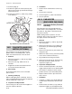
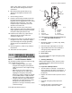
2. Remove solenoid (4) by removing two 1/4-20
by 1/4" Torx head screws.
3. In warranty the pump and motor assembly is
replaced as a complete unit. Out of warranty
the pump and motor can be serviced as
separate items. If further disassembly is
required, mark the orientation of the pump to
the motor and remove two screws which
secure the pump (3) and end head assembly
(2) to the motor (1).
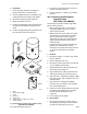
4. Lift pump (3) from motor (1).
c. Cleaning and Drying
Without submerging the motor (1, Fig. 10.69) in
cleaning solvent, clean pump and motor assembly
in an approved cleaning solvent and blow dry.
d. Inspection and Replacement
1. Inspect the pump and motor assembly.
2. Discard the complete pump and motor assem-
bly if the pump (3, Fig. 10.69), end head
assembly (2) or motor (1) is damaged or
defective.
3. Test the coil of the solenoid (4) for continuity.
Discard solenoid if it is damaged or defective.
4. Test solenoid operation using short heavy
gauge wires connected to a fused or protected
6 A minimum output, 12 Vdc power supply.
Discard solenoid if it fails to operate.
5. Test pump motor operation using short heavy
gauge wires connected to a fused or protected
6 A minimum output, 12 Vdc power supply.
Discard motor if it fails to run.
e. Assembly
1. If the pump and motor assembly was disas-
sembled, place the end head assembly (2,
Fig. 10.69) and pump (3) in position on the
motor (1) and secure with two screws.
2. Refer to the orientation marks made in para-
graph b, position the solenoid (4) on the
housing of the motor (1) and install two 1/4-20
by 1/4" Torx head screws.
3. Connect black electric terminal cable (7) by
installing nuts at the solenoid (4) and at the
housing of the motor (1). Torque this top nut
on the ground terminal on the housing of the
motor to 35 lb/in (3,9 N m) maximum.
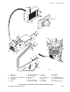
f. Installation
1. Lower pump and motor assembly into position
and secure to machine frame by installing two
3/8-16 UNC hex head capscrews.
2. Connect the supply and pressure hydraulic
hoses to appropriate ports in the end head
assembly (2, Fig. 10.69).
10.14 TROUBLESHOOTING
CONTENTS
Title Page
WARNING DEVICES 10-65
Horn, Backup Alarm, Reverse Switch and
Warning Lights 10-65
CIRCUIT BREAKERS 10-66
STARTING SYSTEM 10-67
Starter, Starting Motor Relay and
Thermo Start Plug 10-68
CHARGING SYSTEM 10-69
Alternator and Batteries 10-69
SWITCHES AND SOLENOIDS 10-71
Ignition and Neutral Start Switches 10-71
Fuel Run Solenoid 10-72
Park Lock Switch and Release Valve Solenoid 10-72
Reverse Switch and Backup Alarm 10-73
Steering Select Switch and Solenoid 10-73
GAUGES AND INDICATOR LIGHTS 10-73
Hourmeter 10-73
Warning Lights 10-74
Engine and Steering Low Oil Pressure Switches 10-74
Engine Coolant High Temperature Switch 10-75
Alternator Warning Light 10-75
Transmission High Oil Temperature Switch 10-75
Fuel Level Gauge 10-76
OPTIONAL LIGHT CIRCUIT 10-76
Directional and Emergency Flasher Switch 10-76
Momentary Brake Light and Switch 10-77
Headlight and Rear Work Light Switch 10-77
WINDSHIELD WASHER/WIPER 10-78
AIR CIRCULATION FAN 10-81
CAB HEATER 10-81
BRAKING AND STEERING PUMP 10-82