Service Manual Model 6036 S/N 9B0499 & Before 8990151 Revised February 11, 2005
Effectivity Page January, 1997 - 001 - Original Issue. February 11, 2005 - B - Replaced all branding with JLG.
Effectivity Page B Model 6036 S/N 9B0499 and Before
SECTION CONTENTS Section Subject Section 1 Safety Practices ................................................................................ 1-1 Section 2 General Instructions .......................................................................... 2-1 Section 3 Boom ................................................................................................. 3-1 Section 4 Operator's Cab ..................................................................................
This Page Left Blank Intentionally
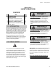
Section 1. Safety Practices SECTION 1 SAFETY PRACTICES CONTENTS Par. 1.1 1.2 1.3 1.4 1.5 1.6 1.7 Title INTRODUCTION SIGNAL WORDS PERSONAL CONSIDERATIONS EQUIPMENT CONSIDERATIONS GENERAL CONSIDERATIONS OPERATIONAL CONSIDERATIONS FINAL WORD Page 1-1 1-1 1-2 1-2 1-3 1-3 1-4 1.1 INTRODUCTION Practically all SERVICE work involves the need to drive the forklift. The Owners/Operators Manual, supplied with each forklift, contains detailed safety practices relating to driving and operating.
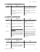
Section 1. Safety Practices 1.3 PERSONAL CONSIDERATIONS Item What to do Why Clothing Do not wear loose clothing or jewelry. Improper clothing can catch on controls or moving parts and cause accidents and/or injury. Eye Protection Always wear appropriate eye protection when chiseling, grinding, discing, welding, painting, when repairing hydraulic systems, or checking, testing or charging the battery. Permanent eye damage can be caused if foreign matter enters the eye.
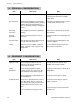
Section 1. Safety Practices 1.4 EQUIPMENT CONSIDERATIONS (cont.) Item Hand Tools What to do Why Always use the proper tool for the job. Many cuts, abrasions, and/or injuries are caused by defective or improper tools. Always keep tools clean and in good working order. Well maintained tools work better and may prevent injury. Always use the Special Service Tools recommended. These tools will reduce the work, labor and costs. 1.
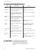
Section 1. Safety Practices 1.6 OPERATIONAL CONSIDERATIONS (cont.) Item What to do Why Ventilation Avoid prolonged running of the engine in a closed area with inadequate ventilation. Exhaust fumes are highly toxic and can kill. Radiator Cap Always turn the radiator cap slowly to the first stop to relieve pressure. Escaping coolant can burn you seriously. Soft Ground Never work on a forklift on soft ground. Check for additional ballast. Seek assistance and install suitable supports if necessary.
This Page Left Blank Intentionally
Section 2 General Instructions SECTION 2 GENERAL INSTRUCTIONS CONTENTS Par. Title Page Par. Title Page 2.9 AFTER SERVICE STARTUP AND CHECKS 2-5 2.1 2.2 2.3 2.4 INTRODUCTION CLEANING REPLACEMENT HOSES AND TUBES 2-2 2-2 2-2 2-2 2.4.1 2.4.2 Inspection Installation 2-2 2-2 2.5 BEARINGS 2-3 2.5.1 2.5.2 2.5.3 Removal Cleaning Installation 2-3 2-3 2-3 2.6 PRESSURE TESTING AND ADJUSTMENT TORQUES 2-3 2-3 2.7. 2.7.1 2.7.2 2.7.3 2.7.4 2.7.
Section 2 General Instructions 2.1 INTRODUCTION Appropriate service methods and proper repair procedures are essential for safe, reliable operation of the forklift and safety of the individual doing the work. This Maintenance Manual provides general directions for accomplishing service and repair work with tested, effective techniques. Following them will assure reliability. There are many variations in procedures, techniques, tools, and parts for servicing vehicles, as well as work skills.
Section 2 General Instructions 2.5 BEARINGS 2.5.1 Removal 1. Bearings should never be removed unless absolutely necessary. Always use the recommended puller to reduce the risk of bearing or related component damage. 2. When bearings or bushings are removed, check that the bearing is free from discoloration, nicks, scuffing, and signs of overheating. If in doubt, replace the bearing or bushing. 2.5.
Section 2 General Instructions 2.7.4 Straight Thread O-ring Fitting (non-adjustable) 1. Make sure both threads and sealing surfaces are free of burrs, nicks, scratches, or any foreign material. 2. Lubricate O-ring with light coating of oil. 3. Torque as follows: 2.8 PAINTING Unless otherwise specified, paint all components as follows: 2.8.1 Orange Paint Use orange paint on all components except as specified in paragraphs 2.8.2 and 2.8.3. P/N 8528033 ..................
Section 2 General Instructions 2.9 AFTER SERVICE STARTUP AND CHECKS 2.9.1 Starting After Servicing NOTE: Refer to Owners/Operators Manual for engine cold start procedure. 1. Check fluid levels. 2. Start engine at idle. Check for leaks from hydraulic components, engine, axles, transmission, brakes and reservoirs. 3. Purge systems of air by operating functions. 4. Check for proper operation. 2.9.5 After Replacing Transmission 1. Check transmission fluid level and replenish as required. 2.
Section 2 General Instructions 2. Clean the area around the magnetic drain plug and remove the plug and check fluid level. Use only Special TRAK Wet Disc Brake Oil (P/ N 8522042) as required to bring level up even with the plug hole. 2.10.5 Splines IMPORTANT: Other brake oils should not be used! You will lose braking force and brake squealing will occur. 2.10.6 Drop Box 3. Clean and install drain plug. 2.10.
This Page Left Blank Intentionally
Section 3. Boom SECTION 3 BOOM CONTENTS Par. Title Page 3.1 3.1.1 3.1.2 3.1.3 3.1.4 3.1.5 3.1.6 3.1.7 3.1.8 3.1.9 3.1.10 3.1.11 BOOM ASSEMBLY Inner Boom Replacement Intermediate Boom Replacement Outer Boom Replacement Chain Replacement Chain Lubrication Chain Tension Check Chain Tension Adjustment Wear Pad Replacement Hose Tensioning Long Term Storage Preparation Boom Lubrication Points 3.2 3.2.2 EMERGENCY BOOM LOWERING Loss of Engine Power or Hydraulic Pump Failure Hydraulic Line Failure 3.
Section 3. Boom c. Installation INNER BOOM QUICK ATTACH PIVOT PIN WITH GREASE FITTING 1. Refer to Fig. 3.3 and install the bottom wear pad on the inner boom. Install a new pad if it is excessively worn (refer to paragraph 3.1.8). Apply Loctite® Removable Threadlocker 242 to the capscrews and torque them to 31 lb-ft (42 N m). GOOSENECK BASE END PIN GRILLE TILT CYLINDER LOCK PIN QUICK ATTACH ASSEMBLY ROD END PIN MA0021 Fig. 3.2 Gooseneck 2. Prepare to replace the inner boom, Fig. 3.
Section 3. Boom CAPSCREW ENDS TO BE FLUSH TO 0.19" (5 mm) RECESSED IN WEAR PAD INSERT PAD, SPACER, INSERT (2), LOCK WASHER (6), FLAT WASHER (6), 3/8-16 X 1-3/4" CAPSCREW (6), 14 GA SHIM GAP MUST BE 0.07 TO 0.13" (1,8 TO 3,3 mm) GAP MUST BE 0.07 TO 0.13" (1,8 TO 3,3 mm) INTERMEDIATE BOOM INNER BOOM CAPSCREW ENDS TO BE FLUSH TO 0.
Section 3. Boom 4. Use a sling and a suitable hoist to slide the intermediate boom out the front of the outer boom. 5. Record the number of shims beneath each wear pad as you remove the rear bottom, Fig. 3.6, and all front wear pads, Fig. 3.5, from the intermediate boom. 6. Examine the chain sheaves for wear and replace if necessary. b. Inspection and Replacement 1. Inspect the boom and welds and contact JLG if structural damage is detected.
Section 3. Boom PAD, INSERT (1), LOCK WASHER (3), FLAT WASHER (3), 3/8-16 X 7/8" CAPSCREW (3) PAD, INSERT (1), LOCK WASHER (3), FLAT WASHER (3), 3/8-16 X 7/8" CAPSCREW (3) GAP MUST BE 0.07 TO O.13" (1,8 TO 3,3 mm) GAP MUST BE 0.07 TO O.13" (1,8 TO 3,3 mm) GAP MUST BE 0.07 TO O.
Section 3. Boom OUTER BOOM INTERMEDIATE BOOM INNER BOOM HOSES HOSE GUIDE CLAMP TUBING SUPPORT PLATE CONNECTION TO MAIN CONTROL VALVE GRILLE TILT CYLINDER MA0081 Fig. 3.8 Grille Tilt Cylinder Hoses 6. Disconnect and cap or plug the grille tilt cylinder tubing, extend cylinder tubes and bulkhead fittings in support plate, Fig. 3.8, below the rear opening of the boom. 7. Loosen clamps that hold the tubing to the bottom of the outer boom and remove the tubing from the outer boom. 8.
Section 3. Boom PAD, INSERT (1), LOCK WASHER (2), FLAT WASHER (2), 3/8-16 X 7/8" CAPSCREW (2) PAD, INSERT (1), LOCK WASHER (2), FLAT WASHER (2), 3/8-16 X 7/8" CAPSCREW (2) GAP MUST BE 0.07 TO 0.13" (1,8 TO 3,3 mm) GAP MUST BE 0.07 TO 0.13" (1,8 TO 3,3 mm) INTERMEDIATE BOOM GAP MUST BE 0.07 TO 0.
Section 3. Boom INNER BOOM SHOULDER SCREW AND LOCKNUT CLEVIS 1-1/2" TO 2-1/2" (38 mm TO 63 mm) YOKE CHAIN LINK PIN AND RETAINING RING INTERMEDIATE BOOM SHOULDER SCREW AND LOCKNUT EXTEND CHAIN BLOCK EXTEND CHAIN, LOCKNUT AND FLAT WASHER OUTER BOOM INNER BOOM INTERMEDIATE BOOM OUTER BOOM RETRACT CHAIN LOCKNUT AND FLAT WASHER CHAIN SUPPORT PLATE RETRACT CHAIN INNER BOOM RETRACT CHAIN LOCKNUT AND FLAT WASHER MA0111 Fig. 3.11 Chain Replacement 11.
Section 3. Boom 3.1.4 Chain Replacement Two chains extend the inner boom and one chain retracts it. Extend Chains IMPORTANT: Replace extend chains in pairs or sets ONLY. 8. Refer to paragraph 3.1.5 and lubricate the chain. 9. Refer to paragraphs 3.1.6 and 3.1.7 and check and adjust the chains. a. Removal 1. Fully retract the boom. 2. Remove the rear boom cover. 3. Refer to Fig. 3.
Section 3. Boom 3.1.5 Chain Lubrication BOOM EXTEND CHAINS 250 Hour Intervals 1. Remove the rear boom cover from the outer boom. 2. Extend and retract the boom several times applying multi-purpose lithium based grease to the entire retract chain with a brush or grease gun. EXTEND CHAIN SHEAVE LUBE FITTING 3. With the boom fully extended, apply multipurpose lithium based grease to the extend chain using a brush or grease gun. 4. Install the rear boom cover on the outer boom.
Section 3. Boom Adjustment is accomplished using extend chain adjustment locknuts, Fig. 3.14. a. Chain Locknut Functions Loosen extend chain locknuts to extend the inner boom and increase extend chain sag. Tighten outer boom retract chain locknut to retract the inner boom and decrease extend chain sag. b. Adjusting Procedure 1. Raise the boom to a horizontal (level) position. Fully extend the boom, then retract it 2" which is 1" per section (51 mm which is 25,5 mm per section). 2.
Section 3. Boom IMPORTANT: Inspect the pads as follows: • Replace wear pads that are less than 0.5" (13 mm) thick. • The ends of wear pad attaching capscrews must not protrude beyond the wear pad insert; the ends must range from flush to 0.19" (5 mm) recessed in the wear pad insert; refer to Fig. 3.3. • When you install a wear pad on one side (including top or bottom) of boom, replace the corresponding wear pad on the other side of the boom.
Section 3. Boom 4. Loosen capscrews securing the hose clamps to the inner boom, Fig. 3.16a or Fig. 3.16b. 5. Manually remove all hose slack between the pulley and the inner boom hose clamps and the pulley and the outer boom tubes. Pull the hoses through the hose clamps, towards the front of the boom, until there is 180° of hose in contact with the pulley. 6.
Section 3. Boom COUNTERBALANCE VALVE IMPORTANT: If the boom has been extended, you must first retract the boom before you attempt to lower the boom. 1. Block the boom so it cannot be lowered. BOOM HOIST CYLINDERS ADJUSTING SCREW RETAINER NUT OA0552 Fig. 3.19 Counterbalance Valves on Boom Hoist Cylinders After the boom has been retracted fully, proceed as follows: 1. At the base of each hoist cylinder, locate the counterbalance valve cartridges, Fig. 3.19.
Section 3. Boom adjusting screw on each cartridge simultaneously into the cartridge very slowly clockwise. Hydraulic oil from inside the hoist cylinders will escape through the fault in the line. 3. If the line failure is in the boom lowering line the boom must be lowered by following the next 3 steps: (a) At the base of each hoist cylinder, locate the counterbalance valve cartridges, Fig. 319. Loosen the retainer nut on each cartridge and turn the adjusting screws in (clockwise) until they bottom out.
Section 3. Boom 3.4 TROUBLESHOOTING Trouble Probable Cause Remedy Reference Broken hydraulic line and/or connection leaks. Locate break and/or stop leaks. Faulty Extend/Retract Cylinder. Repair Cylinder. Section 9 Faulty components in Extend/ Retract hydraulic circuitry. Troubleshoot components and repair or replace components. Section 9 Broken chains or chain connections. Repair or replace chains. See para. 3.1.4 Broken Hydraulic line and/or connection leaks.
Section 3. Boom 3.5 SPECIFICATIONS For 13.00-24 10 ply Tires For 15,00-19.5 12 ply Tires Maximum lift height - boom extended 36 ft. 1 in. (11 m) 35 ft. 5 in. (10,8 m) Maximum lift height - boom retracted 20 ft. 1 in. (6,1 m) 19 ft. 3 in. (11,7 m) Maximum below grade depth - boom extended 39.5 in. (100,3 cm) 40.5 in. (102,9 cm) Maximum reach from front of tire 22 ft. 5 in. (6,8 m) 22 ft. 10 in. (7,0 m) Maximum reach at maximum lift angle - boom extended 45.0 in. (114,3 cm) 50.5 in.
This Page Left Blank Intentionally
Section 4. Operator's Cab SECTION 4 OPERATOR'S CAB CONTENTS Par. 4.1 4.2 Title Page SEAT 4-1 MECHANICAL HAND CONTROLS 4-1 4.2.1 4.2.2 Steering Wheel and Steering Unit Travel Select and Range Select Lever Boom Control and Grille and Frame Tilt Joystick 4-4 MECHANICAL FOOT CONTROLS 4-5 4.3.1 4.3.2 Service Brake Pedal Throttle Pedal and Cable 4-5 4-6 4.4 REAR VIEW MIRRORS 4-8 4.4.1 4.4.2 Mirror Head Adjustment Mirror Cleaning and Inspection 4-8 4-8 4.2.3 4.3 4.
Section 4. Operator's Cab TRAVEL SELECT LEVER FOR FORWARD-F, NEUTRAL-N, AND REVERSE-R RANGE SELECT LEVER FOR LOW-1, MEDIUM-2, AND HIGH-3 GATE PLATE BELL CRANKS SHIFTER ASSEMBLY CLEVIS PIN, WASHER, AND COTTER PIN SWIVEL COTTER PIN AND WASHER LOCKNUT CABLE MOUNTING STRAP REVERSE SWITCH CONTROL CABLE ANGLE BRACKET LOCKNUT AND CAPSCREW REVERSE SWITCH LEAD WIRES CLAMP MA0141 Fig. 4.3 Shifter Assembly 4.2.
Section 4. Operator's Cab b. Transmission Cable Removal Maintenance 1. Prepare to clean and lubricate the spring, disk and ball in each travel and range select lever mechanism by removing the cotter pins, washers and clevis pins that secure each lever to the shifter assembly. Remove the levers from the shifter assembly. 2. Clean each lever spring, disk, and ball with an approved solvent. Replace defective or damaged parts as required. Apply a multipurpose grease to each disk, spring, and ball. 3.
Section 4. Operator's Cab 4.2.3 Boom Control and Grille and Frame Tilt Joysticks The Boom Control Joystick raises, lowers, retracts, and extends the boom. The Grille / Frame Tilt Joystick tips the carriage up or down and tilts the frame left or right. See the Owners/Operators Manual for operational descriptions. A control cable attached to each joystick assembly, Fig. 4.5, terminates at a valve section on the main control valve, Fig. 4.6. JOYSTICK ASSEMBLY a. Joystick Assembly Removal 1.
Section 4. Operator's Cab 4. Install the covers on the joystick assembly. 5. Install the lower panel. BRAKE VALVE PUSH ROD JAM NUT b. Joystick Control Cables Removal 1. Remove the lower panel which is below the side console. 2. Remove the covers from the joystick assembly, Fig. 4.5. 3. Loosen the lock screw until the control cable, with lock screw and cable bushing, can be removed from the slider. 4. Unthread cable bushing from cable and remove lock screw from cable. 5. Remove the transmission cover. 6.
Section 4. Operator's Cab PEDAL LIMIT STOP SCREW CAB FLOOR LOCKNUT WASHER CLAMP LEVER ASSEMBLY CABLE SUPPORT CLEVIS PIN AND LOCK CLIP THROTTLE CABLE SPRING JAM NUT MA0191 CLEVIS Fig. 4.8 Throttle Pedal 2. Install the spring on the pedal and hook the other end over the support inside the console. 3. Slide push rod into brake valve and secure the yoke to the pedal with clevis and cotter pins. 4. Check the brake valve capscrews to be sure they are torqued to 30 lb-ft (40,8 N m). a.
Section 4. Operator's Cab 2. Adjust the limit stop screw until it touches the pedal. 7. Remove the long clevis and jam nut from the cable end. 3. Tighten the locknut to 120 to 125 lb-inch (13,6 to 14,1 N m). 8. Remove the throttle cable from the forklift. 4. Check engine rpm at full throttle. If not 2600 to 2860 rpm, readjust the limit stop screw. IMPORTANT: During the full throttle check • operate no hydraulic function, • do not steer, and • be sure the transmission is in neutral. b.
Section 4. Operator's Cab 4.4 3. Tighten “preset” pivot bolt to a 3/16" (5 mm) gap as shown in Fig. 4.11. REAR VIEW MIRRORS The forklift has two rear view mirrors. • A 6-1/2 by 10" flat glass mirror on the cab frame to the left of the operator. • A 6-1/2 by 6" convex glass mirror on the forklift frame to the right of the operator. The mirrors have an outer gasket for edge shock protection. If a mirror shatters, a replacement mirror can be installed in the mirror head. 4.4.
This Page Left Blank Intentionally
Section 5. Wheel Assembly, Tires, and Axle SECTION 5 WHEEL ASSEMBLY, TIRES, AND AXLE CONTENTS Par. Title 5.1 WHEEL ASSEMBLY AND TIRE 5.1.
Section 5. Wheel Assembly, Tires, and Axle 5.1 WHEEL ASSEMBLY AND TIRE Warning ! Whenever you remove tire(s) and wheel(s) from forklift: • Position forklift on a flat, hard surface and support forklift with approved jack stands. • Use appropriate safety glasses, safety shoes and appropriate clothing and equipment. • Do not wear rings or jewelry or use clothing or hair styles that could become caught in machinery or pinch points such as those created between tire and hub.
Section 5.
Section 5. Wheel Assembly, Tires, and Axle FIXED SIDE FLANGE AND TIRE SEAT LOOSE SIDE FLANGE AND TIRE SEAT RIM BASE LOCK RING EMBOSSED VALVE HOLE TR618A AIR-WATER TYPE VALVE O-RING SEALING RING MA0221 Fig. 5.2 Standard Wheel Assembly with T-Type Rim and Fixed Back Flange Tire and wheel maintenance is covered in the following paragraphs: 5.1.1 Removing Hydrofill from Tire or Tube within Tire 5.1.1 1. Be sure you’ve read and understood the warning notices and general instructions in paragraph 5.1.
Section 5. Wheel Assembly, Tires, and Axle START BEAD ON THIS SIDE OF RIM DEEP WELL MA0231 Fig. 5.3 Optional Wheel Assembly with Single Piece Rim 5.1.2 Demounting Tire IMPORTANT: Always completely deflate tire as described in paragraph 5.1.1 before you attempt to demount tire. 1. Be sure you’ve read and understood the warning notices and general instructions in paragraph 5.1. 2. To remove a wheel from the forklift refer to paragraph 5.1.5. 5.1.
Section 5. Wheel Assembly, Tires, and Axle 5.1.5 Demounting Optional Tire from Single Piece Wheel CLIP-ON CHUCK IMPORTANT: Always completely deflate tire as described in paragraph 5.1.1, before you attempt to demount a tire. CORE EJECTOR BODY CORE REMOVER 1. Be sure you’ve read and understood the warning notices and general instructions in paragraph 5.1. EJECTOR CHUCK PACKING NUT 2. Place the wheel and tire assembly on the floor on blocks with the narrow ledge on the bottom, Fig. 5.3.
Section 5. Wheel Assembly, Tires, and Axle 9. Remove the valve stem from the rim base. 5.1.9 Mixing Hydrofill Solution 10. Refer to paragraph 5.1.12 for tire mounting instructions. Prepare the hydrofill mixture by pouring calcium chloride into water; never add water to calcium chloride as considerable heat is generated in this mixing process. Let the solution cool to atmospheric temperature before pumping it into the tire.
Section 5. Wheel Assembly, Tires, and Axle 5. Inspect both sides of the tire to be sure beads are evenly seated. If not, completely deflate tire, unseat beads and repeat entire mounting procedure. 6. Lower jack until tire is slightly deflected. With pump not running and the pump control handle at CHECK position, connect ejector and remove core housing as described in paragraph 5.1.1. 7. After connection is made, bleed pressure down to about 5 psi (0,35 bar) by moving pump control to EVACUATE.
Section 5. Wheel Assembly, Tires, and Axle 6. Lubricate a new rubber O-ring. Place O-ring in groove on one side and stretch O-ring snapping it into place rather than rolling it into place. The lubricate the entire O-ring groove areas with an approved vegetable-based lubricant. NOTE: It may be necessary to hold the side flange down with the flat end of the tire iron to expose the O-ring groove. 7. Check the components to make certain they are correctly assembled .
Section 5. Wheel Assembly, Tires, and Axle 5.1.15 Installing a Wheel on the Forklift experience shows was started by the overheated condition that developed when the unit was towed at high speed. 1. Be sure you’ve read and understood the warning notices and general instructions in paragraph 5.1. 2. Remove the wheel assembly from the safety cage and place it on the axle hub. 3. Secure the wheel assembly to the axle hub with ten wheel lug nuts. Torque the nuts to 450 to 500 lb-ft (612 to 680 N m).
Section 5. Wheel Assembly, Tires, and Axle 5.2 AXLE ASSEMBLY The axle assembly rotates and turns the wheels. Both front and rear axles consist of a differential carrier assembly, a left and right axle steering joint, and a left and right wheel end, Fig. 5.6.
Section 5. Wheel Assembly, Tires, and Axle IMPORTANT: • When replacing a fastener, replace it with one of equal or higher grade and quality. Torque fasteners are recommended for the application. • Some service operations require the use of tools specifically designed for the purpose. Use the special tools when and as recommended. • Hammering on end yokes or flanges to remove or install them is not only destructive to the yoke or flange itself, but can also cause serious internal damage.
Section 5. Wheel Assembly, Tires, and Axle Warning ! from the mounting blocks. Wait for the hydraulic fluid to cool before servicing any hydraulic component. Hot hydraulic fluid can cause severe burns. 3. Place adequate support under the frame so that it will remain in place when the axle assembly is removed. 4. Remove the wheels from the axle as described in paragraph 5.1.3. 5. Use floor jacks or install a suitable hoist at the ends of the axle. Take up the slack. 6.
Section 5. Wheel Assembly, Tires, and Axle 27 26 28 41 40 39 42 37 36 38 24 34 35 32 23 30 43 31 29 21 20 19 22 10 17 13 18 11 12 11 25 10 8 7 14 16 15 9 5 4 PA0332 6 2 2. 3. 4. 5. 6. 7. 8. 9. 10. 11. 12. 13. 14. 15. 16. Screw, self-locking Planetary Gear Assembly Flange, planetary drive Plug, drain/fill Plug Pin, roll Shaft, planet gear Washer, drive flange Washer, keyed Bearing, single roller Ring, spacer Gear, planet Plate, lining stop Ring, retaining Gear, sun spur 17. 18 19.
Section 5. Wheel Assembly, Tires, and Axle 5. Connect hydraulic hoses as required to steering cylinders, service brakes and park lock. Bleed the lines to the service brakes and park lock. 6. Remove the hoist from the ends of the axle. 7. Install the wheels on the axle as described in paragraph 5.1.15. 8. Remove the support from under the frame. Warning ! Before starting the engine be sure all hydraulic connections are tight and all tools are removed from the forklift. c. Cleaning and Drying 1.
Section 5. Wheel Assembly, Tires, and Axle 30 31 29 28 26 24 25 27 23 19 10 13 11 12 22 11 10 20 18 8 7 4 17 5 16 15 14 6 9 2 PA0322 1. 2. 3. 4. 5. 6. 7. 8. 9. Wheel End Assembly Screw, self-locking Planetary Gear Assembly Flange, planetary drive Plug, drain/fill Plug Pin, roll Shaft, planet gear Washer, drive flange 10. 11. 12. 13. 14. 15. 16. 17. Washer, keyed Bearing, single roller Washer, planet gear Gear, planet Ring, retaining Gear, sun spur Spacer, flat Gear, planetary ring 18 19.
Section 5. Wheel Assembly, Tires, and Axle 3 After drying, components should be lightly coated with oil or rust preventive to protect them from corrosion. 2. Support the hub assembly with a lifting device. c. Inspection and Replacement 3. Refer to page 15 of Spicer® Dana Maintenance Manual for Axle Models PS/PR-7036 for disassembly instructions. 1 b.
Section 5. Wheel Assembly, Tires, and Axle 22 23 24 25 11 10 9 26 7 8 25 24 1 5 4 5 17 18 23 6 3 16 22 19 2 20 21 13 12 15 14 21 20 19 18 17 1. 2. 3. 4. 5. 6. 7. Shaft and Joint Assembly Shaft, outer Cross Assembly Bearing Race Assembly Ring, retaining Yoke, center Shaft, inner yoke, left 8. 9. 10. 11. 12. 13. 16 PA0312 Shaft, inner yoke, right Deflector, seal Seal, oil Bushing, spindle Knuckle Assembly Stud, dowel 14. 15. 16. 17. 18. 19.
Section 5. Wheel Assembly, Tires, and Axle a. Disassembly 1. Refer to page 13 through 16 of Spicer® Dana Maintenance Manual for Axle Models PS/PR7036 for removing and disassembling the drive flange and wheel end hub. 2. On an axle with service brakes: (a) Remove lining stop plates (14 and 17, Fig. 5.8) and disc assemblies (18). 5. Tap the spindle with a soft-faced hammer to loosen the knuckle assembly (12, Fig. 5.10). Remove the spindle assembly. 6. Replace oil seal or bronze bushing (42, Fig. 5.
Section 5. Wheel Assembly, Tires, and Axle 4. Replace roller bearing cups (24) or cones (23) if any are worn, pitted, or damaged. 5. Replace oil seals (10 and 22) regardless of condition. d. Retaining Ring Inspection 1. Place the forklift in “Crab Steer” mode and turn the steering wheel full left to access shaft assemblies on the right side of the vehicle 2. Using a flashlight, visually inspect the right front shaft assembly retaining rings through the opening between the axle housing and steering knuckle.
Section 5. Wheel Assembly, Tires, and Axle turn and align any hole in the nut with a major spline on the spindle. Mark the end of the aligned spline on the edge of the spindle. Make sure the hub rotates freely. (d) Install roll pin (19) on the back face of planetary ring gear (17) and mark its location on the front face of the gear. (e) Install planetary ring gear, making sure roll pin is locked into locknut hole.
Section 5. Wheel Assembly, Tires, and Axle 2 17 10 9 9 9 11 7 15 3 6 8 4 8 8 24 12 1 19 20 22 21 13 23 16 18 5 14 PA0281 1. 2. 3. 4. 5. 6. Screw, socket head cap (4) Plate, cover Spline, outer Spring, red (12) Plate, pressure Plate, spring 7. 8. 9. 10. 11. 12. Screw, socket head cap (4) Disc, rotor (7) Plate, lining (7) Plate, thrust Bolt, socket head shoulder (4) Screw, bleeder 13. 14. 15. 16. 17. 18. Ring, retainer Bearing Ring, retainer Seal, oil Seal, oil Seal, case (2) 19. 20.
Section 5. Wheel Assembly, Tires, and Axle PIN LINING PLATE THRUST PLATE CAPSCREW SHOULDER BOLT MA0291 Fig. 5.14 Plate and Disc Alignment c. Cleaning and Drying e. Assembly 1. Clean all parts with approved petroleum based cleaner. Refer to page 55 of Spicer® Dana Maintenance Manual for Axle Models PS/PR-7036 for assembly instructions. 2. Use clean lint free towels to dry components after cleaning. DO NOT dry bearings by spinning with compressed air.
Section 5. Wheel Assembly, Tires, and Axle 7 8 10 9 46 8 10 41 7 9 11 5 43 42 12 43 2 3 4 4 3 44 2 13 17 18 16 14 45 15 22 19 23 24 28 29 25 26 30 31 35 27 22 34 32 39 33 40 21 PA1360 37 38 36 1. 2. 3. 4. 5. 6. 7. 8. 9. 10. 11. 12. 13. 14. 15. 16. 17. 18. 19. 20. 21. 22.
Section 5. Wheel Assembly, Tires, and Axle 8 10 7 9 41 8 10 11 45 42 40 7 9 5 12 42 2 3 4 4 3 2 13 14 17 16 43 15 18 23 22 19 44 21 24 29 25 28 26 31 22 27 33 34 30 32 36 39 35 PA1530 37 38 1. 2. 3. 4. 5. 6. 7. 8. 9. 10. 11. 12. 13. 14. 15. 16. 17. 18. 19. 20. 21. 22.
Section 5. Wheel Assembly, Tires, and Axle PIVOT PIN KNUCKLE STEER CYLINDER BALL JOINT TIE ROD BALL JOINT KNUCKLE OA0192 Fig. 5.17 Axle Grease Points 5.3 Warning ! • Do not attempt carrier and differential removal and installation and differential and pinion disassembly and assembly without thoroughly understanding instructions in Spicer® Dana publications and correspondence which applies to your forklift.
Section 5. Wheel Assembly, Tires, and Axle Level Check (250 hour intervals) AXLE FILL AND LEVEL PLUG 1. Level the forklift, ground the carriage, shut off the engine, and engage the park lock. Be sure that the arrow on the wheel end housing is pointing down (Fig. 5.19). 2. Clean the area around the magnetic drain plug and remove the plug. AXLE DRAIN PLUG OA0422 Fig. 5.18 Axle Fill and Drain Plugs Change (1000 hour intervals) 1. Place a receptacle under the axle housing drain plug (Fig. 5.18). 2.
Section 5. Wheel Assembly, Tires, and Axle Oil Capacity of Wheel End Front-54 oz. (1,6 liter) Special TRAK Wet Disc Brake Oil (P/N 8522042) Rear-56 oz. (1,7 liter) Special TRAK Wet Disc Brake Oil (P/N 8522042) Park Lock Unit Type: Multiple Disc Park Lock, spring apply hydraulic release (dry disc design) Maximum Speed: 1700 rpm Release Pressure: 364 psi (2 512,0 kPa) min. 3000 psi (20 700,0 kPa) max. Torque Rating: 17,000 in. lbs (19 210,0 N m) static (breakaway) Volume displacement to release park lock: 1.
This Page Left Blank Intentionally
Section 6. Drive Shafts and Drop Box SECTION 6 DRIVE SHAFTS AND DROP BOX CONTENTS Title 6.1 DRIVE SHAFT ASSEMBLIES 6-1 6.1.1 Drive Shaft Servicing 6-1 6.2 DROP GEAR BOX 6-3 NOTE: Wrap tape around bearings and cross so bearings do not drop off cross. 6.2.1 6.2.2 6.2.3 End Yokes Oil Seals Internal Inspection and Servicing 6-3 6-4 6-4 4. Remove the axle drive shaft assembly from the forklift. 6.3 SPECIFICATIONS 6-4 b. Disassembly 6.1 Page 3.
Section 6.
Section 6. Drive Shafts and Drop Box c. Cleaning and Drying 1. Disassemble and clean all parts using an approved cleaning fluid. 2. Remove any burrs or rough spots from any machined surfaces. d. Inspection and Replacement 1. Individually inspect each cross, bearing caps and needle bearings for signs of wear or missing parts. Drive Shaft–Transmission to Drop Gear Box 1. Position the drive shaft assembly on the forklift so slip joint mounts to the drop box, Fig. 6.1. 2.
Section 6. Drive Shafts and Drop Box a. Inspection Replace oil seal (4, Fig. 6.4) if worn or damaged. b. Removal To remove oil seal, remove screw (1), Fig. 6.4, washer (2), end yoke (3) and oil seal (4). c. Installation 1. To install oil seal, press oil seal and yoke on shaft. 2. Press yoke (3, Fig. 6.4) on shaft and secure with washer (2) and screw (1). 6.2.3 Internal Inspection NOTE: JLG does not recommend servicing of gears, shafts or bearings inside this drop box.
Section 6. Drive Shafts and Drop Box VENT/FILL PLUG OIL SEAL END YOKE SCREW & WASHER SCREW & WASHER END YOKE OIL SEAL FRAME DROP BOX INSPECTION COVER CAPSCREW LEVEL PLUG (on late models) LOCK WASHER LEVEL PLUG (on early models) OIL SEAL END YOKE SCREW & WASHER DRAIN PLUG PA0261 Fig. 6.
This Page Left Blank Intentionally
Section 7. Transmission SECTION 7 TRANSMISSION, CLARK SERIES 18000 7.1.1 Daily or 10 Hour Intervals CONTENTS Par. Title Page 7.1 TRANSMISSION PREVENTIVE MAINTENANCE 7-1 7.1.1 7.1.2 7-1 7.1.3 Daily or 10 Hour Intervals First 50 Hours and 500 Hour Intervals Thereafter 1000 Hour Intervals 7-1 7-2 7.2 HOW TO TOW THE FORKLIFT 7-2 7.3 HOW TO DRAIN TRANSMISSION 7-2 7.4 HOW TO BACK FLUSH OIL COOLER 7-3 7.5 TRANSMISSION REMOVAL 7-3 7.6 TRANSMISSION REPLACEMENT 7-3 7.
Section 7. Transmission 3. Remove sump plug and screen with gasket from housing, Fig. 7.3. Allow the transmission to drain completely. TRANSMISSION FILTER 4. Clean the plug and screen thoroughly with an approved solvent. 5. Install a new filter element as described in paragraph 7.1.2. DO NOT START ENGINE. 6. Install the cleaned drain plug and screen and gasket into the transmission sump housing. 7. Add tractor hydraulic fluid as required to bring fluid level up to full mark. Transmission capacity is 4.
Section 7. Transmission 7.4 HOW TO BACK FLUSH OIL COOLER The transmission oil cooler, Fig. 7.4, is mounted behind the radiator. Periodically disconnect and back flush the oil cooler with oil and compressed air until all foreign material has been removed. If necessary, remove oil cooler from forklift and clean it using oil, compressed air and steam. IMPORTANT: DO NOT use flushing compounds for cleaning purposes. 7.5 TRANSMISSION REMOVAL Please refer to paragraph 8.
Section 7. Transmission 7.
Section 7. Transmission 7.10 SPECIFICATIONS System Capacity (inc. filter and oil cooler) 4.3 gallons (16,3 liter) Filter Capacity 1 quart (0,95 liter) Tractor Fluid John Deere J20 A Detroit Diesel C-3, C-2 Ford Tractor M2C134B White Farm UTHF Q1766, Q1722 Converter: Outlet oil temperature Outlet pressure 180 to 200 °F (82 to 93 °C) Transmission in Neutral. 25 psi (1,72 bar) minimum pressure at 2000 rpm engine speed 70 psi (4,82 bar) outlet pressure with engine operating at no-load governed speed.
This Page Left Blank Intentionally
Section 8. Engine SECTION 8 ENGINE, PERKINS SERIES 4.236 AND T4.236 CONTENTS Page 8-2 Throughout this section, the left or right side of the engine is the side of the engine when viewed from the flywheel end. Par. 8.1 Title ENGINE PREVENTIVE MAINTENANCE 8.1.1 8.1.2 8.1.3 8.1.4 8.1.5 8.1.6 8.1.7 8.1.8 8.1.9 8.1.
Section 8. Engine IMPORTANT: These instructions cover only the routine maintenance of the engine. Refer to your Perkins Engine Distributor for engine diagnosis, repair and component replacement. A gradual running in of a new engine is not necessary. Full load can be applied to a new engine as soon as the engine is put into service and the coolant temperature is at least 140 °F (60 °C). Extended light load operation during the early life of the engine is not recommended.
Section 8. Engine 4. Remove the air cleaner cover wing nut, cover, and primary element, Fig. 8.5. RESTRICTION INDICATOR INDICATOR WINDOW Warning ! T H EX ER T E Wear safety glasses when using compressed air to clean element. OA0202 Fig. 8.3 Air Cleaner Restriction Indicator 2. Unlock and open left rear engine access door. Check air cleaner restriction indicator, Fig. 8.3. If red band has appeared, the primary element must be cleaned or replaced (steps 4 thru 8).
Section 8. Engine Engine Coolant 1. Level the forklift, lower carriage to ground, shut off engine and engage park lock. 2. Unlock and open the right rear engine access door. 2. Level forklift, lower the carriage to ground, shut off engine, and engage park lock. 3. Place a receptacle under the engine oil pan drain plug. 4. Remove drain plug on rear face of the engine oil pan and allow oil to drain completely into receptacle. 5. Unlock and open the right rear access door. 6. Remove the oil filter, Fig. 8.7.
Section 8. Engine 3. Loosen drain cock on bottom of fuel pre-filter and allow water to completely drain from it. 4. Tighten the drain cock and top bleed screw after draining. 5. Close and lock the right rear engine access door. 5. Position a new filter element between the base and head and install and tighten screw on top of filter assembly until snug. 6. Remove air from the fuel system. (See paragraph 8.4.8, How to Bleed to Fuel System). 7. Close and lock the right rear engine access door.
Section 8. Engine INJECTOR HIGH PRESSURE LINE FITTINGS GOVERNOR VENT SCREW INJECTION PUMP VENT SCREW OA0342 Fig. 8.13 Injector High Pressure Line Fittings OA0322 Fig. 8.11 Vent Screws in Injection Pump 1. Unlock and open the right rear engine access door. Loosen the governor vent screw in the fuel injection pump governor control cover, Fig. 8.11. 2. Loosen the injection pump vent screw on the side of the fuel injection pump. 5. Loosen any two high pressure fittings, Fig. 8.
Section 8. Engine 8.1.7 2,500 Hour Intervals 1. Inspect and service proprietary equipment such as starter motor, alternator, turbocharger (if applicable) etc. 2. Service atomizers (fuel injectors), para. 8.4.9. CYLINDER BLOCK DRAIN PLUG 3. Check and adjust valve tip clearances, para. 8.10. 8.1.8 Annually Engine Coolant Change OA0262 Fig. 8.16 Cylinder Block Drain Plug Warning ! 6. Remove cylinder block drain plug, Fig. 8.16, and drain engine block. Replace drain plug.
Section 8. Engine 8.1.10 Lubricating Oils Lubricating oils for naturally aspirated engines should meet the requirements of U.S. Ordnance Specification MIL-L-46152 or MIL-L-2104C. Lubricating oils for turbocharged engines should meet U.S. Ordinance Specification MIL-L-2104C. Do not use a lubricating oil to the MIL-L-2104C specification in naturally aspirated engines for the first 500 to 1,000 miles (25 to 50) hours of operation.
Section 8. Engine An approved antifreeze as described in paragraph 2 protects against corrosion and also raises the boiling point of the coolant. A 50 percent concentration of antifreeze is preferred, but if there is a less likely chance that this much frost protection is required, a mixture of not less than 33 percent concentration can be used. If antifreeze is not used, add an approved corrosion inhibitor mixture to the water.
Section 8. Engine 8.2.3 Integral Oil Cooler in Oil Filter The oil filter for a turbocharged engine, Fig. 8.17, has an integral oil cooler. Whenever you change engine coolant, drain the oil cooler by removing inlet or outlet connections, flush the cooler and reconnect hose. 8.3 ENGINE ELECTRICAL SYSTEM The engine electrical system is described in Section 10, Electrical System.
Section 8. Engine 2 3 6 5 4 1 9 19 7 9 8 5 10 TO LIFT PUMP 5 17 TO THERMO START 19 FROM LIFT PUMP 20 5 11 5 TO FUEL INJECTION PUMP FROM FUEL INJECTION PUMP 22 23 18 5 11 15 13 12 14 16 21 PA0424b 1. 2. 3. 4. 5. 6. 7. 8. Fuel Tank Fuel Level Sender Filler Cap with Tether Elbow, 90°, with standpipe Hose Clamp Fuel Return Hose Fuel Supply Hose Fuel Supply Hose 9. 10. 11. 12. 13. 14. 15. 16.
Section 8. Engine 3. For a short term repair you may be able to repair a small leak by installing a sheet metal screw with a neoprene gasket in the opening. Replace tank for long term repair. b. Disassembly 1. Remove five capscrews, fuel level sender (2, Fig. 8.18) and gasket from fuel tank. 2. Remove fuel supply and return elbows (4 and 20) and rubber bushings (19) from fuel tank. c. Cleaning and Drying Warning ! This procedure will not remove all fuel vapor.
Section 8. Engine a. Removal 1. Remove fuel pre-filter inlet and outlet tubes (11, Fig. 8.18). 5. Remove air from the fuel system. (See paragraph 8.4.8, How to Bleed to Fuel System). 2. Support filter with one hand and remove lock nuts (15) and capscrews (14) and remove fuel pre-filter from mounting bar. 6. Close and lock access door. a. How to Test the Fuel Lift Pump in Position 1. Disconnect the outlet line from the lift pump to the fuel filter. 3.
Section 8. Engine e. Fuel Lift Pump Installation 8.4.6 Fuel Filter Position the fuel lift pump on the engine and install the four capscrews and lock washers that secure the fuel lift pump to the engine. Change element (5, Fig. 8.21) every 500 hours of operation. 2 8 1. Unlock and open the right rear engine access door. 2. Loosen hex screw in top of filter, Fig. 8.9, and lower filter bowl cover. 3 7 4 3. Remove and discard element and gaskets. 5 4.
Section 8. Engine 8.22 AI 29 22 13 12 25 26 24 11 10 23 32 17 15 4 2 30 19 20 18 31 3 14 16 21 5 33 27 1 28 7 9 6 8 MA0361 1. 2. 3. 4. 5. 6. 7. 8. 9. 10. 11. Fuel Injection Pump Sleeve Seal Wire Gasket Stud (3) Nut (3) Washer (3) Washer (3) Injection Pipe for No. 1 Cylinder Injection Pipe for No. 2 Cylinder 12. 13. 14. 15. 16. 17. 18. 19. 20. 21. 22. Injection Pipe for No. 3 Cylinder Injection Pipe for No.
Section 8. Engine e. Fuel Injection Pump Installation 8.4.7 Fuel Injection Pump The fuel injection pump, Fig. 8.22, is a distributor type pump with a mechanical flyweight type governor. The pump is flange mounted and is driven from the engine timing case. IMPORTANT: Unless the necessary equipment and experienced personnel are available, dismantling of the fuel injection pump should not be attempted. a.
Section 8. Engine rigid spacer. Tighten securing nuts evenly to 12 lb-ft (16 N m). a. How to Locate Faulty Atomizer(s) A faulty atomizer can cause: • Misfiring • Knocking in one (or more) cylinders b. Atomizer Identification Currently, the atomizer code is stamped on the atomizer body. c. How to Replace an Atomizer • Engine overheating 1. Remove the fuel leak off pipe. • Loss of power 2. Remove the high pressure pipe union nuts from the atomizer and fuel injection pump and release the pipe.
Section 8. Engine Whenever you replace a muffler you should also replace the tail pipe. When installing an exhaust system be careful to provide for expansion when the system is hot. Use Exhaust System Sealer at all slip joint connections before assembly. Check complete exhaust system for broken, damaged, missing or mispositioned parts, open seams, holes, loose connections, and other deterioration which could permit exhaust fumes to seep into the operators cab.
Section 8. Engine 1 3 2 Removal from Naturally Aspirated Engine (a) Loosen clamp that secures the elbow to the engine inlet manifold. 6 (b) Loosen clamp that secures the elbow to the air cleaner assembly. 4 Removal from Turbocharged Engine 5 MA0371 1. 2. Screw (2) Washer (2) 3. 4. Plate Screw (2) (c) Remove the nuts, lock washers, washers and capscrews that secure the air cleaner mounting band to the forklift frame. 5. 6.
Section 8. Engine 13. Disconnect the engine wire harness at the following components, Fig. 8.26: • Starter • Starter Ground Cable • Starter Relay • Neutral Start Switch (on transmission) • Transmission Temperature Switch • Low Oil Pressure Sender • Emergency Pump Oil Pressure Switch • Water Temperature Sender • Fuel Run Solenoid • Alternator • Thermo Start Plug 15. Detach throttle cable from engine as follows: (a) Remove cable clamp securing throttle cable to throttle cable bracket.
Section 8. Engine 8.7 (b) Remove the U-bolt assembly or bearing straps, Fig. 6.1, attaching the drive shaft cross assembly to the drop box input shaft yoke. Slide slip joint towards transmission so cross slips out of drop box input shaft yoke. NOTE: Wrap tape around bearings and cross so bearings don't drop off cross. (c) Remove the cap and bolt assembly or bearing straps securing the drive shaft cross assembly to the transmission output shaft yoke.
Section 8. Engine 10. After all eight capscrews have been installed, rotate the engine flywheel again and individually torque all eight to 25 to 30 lb-ft (34 to 40,8 N m). 11. Install the engine and transmission on the forklift frame as follows: 13. Secure transmission drive shaft to transmission with U-bolt or bearing strap. Torque U-bolt to 20 to 24 lb-ft (27 to 37 N m) or bearing strap to 55 to 60 lb-ft (75 to 82 N m). 14.
Section 8. Engine 15. Attach the throttle control cable to the engine fuel injection pump as follows: (a) Fasten the throttle cable to the throttle cable bracket with a clamp being sure to align the grooves in the cable and clamp. (b) Secure the throttle cable clevis to the fuel injection pump throttle and stop lever with cotter and clevis pins. Adjust the clevis so that the lever touches the stop screw. 16. Connect the fuel lines to the fuel pre-filter and fuel filter assemblies. 17.
Section 8. Engine 8.9 HEAD TORQUE CHECK 1. Run engine until coolant outlet temperature is higher than 170 °F (77 °C). 2. Stop the engine and remove the cylinder head cover. 3. Check the torque of the cylinder head nuts and capscrews in the correct sequence as shown in Fig. 8.29. The correct torque is 100 lb-ft (136 N m) for 1/2" studs and capscrews; 60 lb-ft (84 N m) for 7/16" studs. • If a nut or a capscrew turns when checked, tighten it to the correct torque.
Section 8. Engine clearances of No. 2 cylinder valves. tion manifold. Seal the manifold with waterproof tape. 8.11 ENGINE STORAGE 12. Remove the exhaust pipe. Spray POWERPART Lay-Up 2 into the exhaust manifold. Seal the manifold with waterproof tape. Use the following procedures immediately when engine is removed from service for an extended period. The instructions for the use of Perkins POWERPART products are given on the outside of each container. 1. Clean outside of engine. 2.
Section 8. Engine 8.
This Page Left Blank Intentionally
Section 9. Hydraulic System SECTION 9 HYDRAULIC SYSTEM CONTENTS Warning ! Par. Title 9.1 CIRCUITS 9.1.1 9.1.2 9.1.3 9.1.4 9.1.5 9.1.6 9.1.7 Boom Raise/Lower Boom Extend/Retract Grille Tilt and Slave Circuit Frame Tilt Circuit Brake Circuits Power Steering Circuit Optional Auxiliary Circuit 9-1 9-5 9-8 9-11 9-14 9-17 9-20 9.2 CYLINDERS 9-23 9.2.1 9.2.2 9.2.3 9.2.4 9.2.5 9.2.6 9.2.
Section 9. Hydraulic System MAIN CONTROL VALVE TO FRAME TILT CYLINDER TO GRILLE TILT AND SLAVE CYLINDERS DIRECTIONAL CONTROL VALVE POSITIONS RAISE TO BOOM EXTEND/ RETRACT CYLINDER RIGHT BOOM HOIST CYLINDER LOWER A B C A B C A B C D E F D E F CENTER D E F LOWER RAISE MAIN RELIEF VALVE BOOM HOIST RELIEF VALVE LEFT BOOM HOIST CYLINDER TANDEM PUMP 30 GPM RESERVOIR STRAINER 15 GPM RETURN FILTER 0-4000 psi PRESSURE GAUGE COUNTERBALANCE VALVES MA0421 Fig. 9.
Section 9. Hydraulic System ing, the counterbalance valve would lose pilot pressure closing off flow returning to the reservoir. The oil in the base end of the cylinder would then be trapped, which would immediately stop boom lowering and prevent an elevated load from falling to the ground uncontrolled. The load can be lowered safely to the ground by following the “Emergency Boom Lowering” procedures in your Owners/ Operators Manual. IMPORTANT: DO NOT attempt to reset the counterbalance valve cartridges.
Section 9. Hydraulic System FRAME TILT "RIGHT" PORT RELIEF VALVE GRILLE TILT "UP" PORT RELIEF VALVE BOOM EXTEND PORT RELIEF VALVE MAIN RELIEF VALVE 4. Install a tee and pressure gauge capable of measuring 0 - 4000 psi (275,6 bar) in the tandem pump outlet of the 30 gpm section, Fig. 9.1. Warning ! Before starting the engine be sure all hydraulic connections are tight and all tools are removed from the forklift. 5. Start the engine.
Section 9. Hydraulic System 5. Starting at the fully raised position, lower the boom at full engine speed. The time required to lower the boom to its lowest position should be 8 to 10 seconds (no load). suction stainer in the reservoir, Fig. 9.3. Supply pressure is directed to either side of the extend/ retract cylinder piston by the shifting of a spool in a directional control valve found in the main control valve assembly. The spool is shifted by the operator joystick and its associated control cable.
Section 9. Hydraulic System Extend Position When the joystick is placed in the extend position, the directional control valve spool is shifted so that supply pressure is directed through ports E to A, Fig. 9.3, to the base end of the boom extend cylinder piston. If supply pressure reaches 2650 psi (182,6 bar), the boom extend port relief valve, Fig. 9.2, will open allowing hydraulic oil to return to the reservoir.
Section 9. Hydraulic System Warning ! Before starting the engine be sure all hydraulic connections are tight and all tools are removed from the forklift. 3. Remove the transmission cover from the frame. 4. Install a tee and pressure gauge capable of measuring 0 - 4000 psi (275,6 bar) in the tandem pump outlet of the 30 gpm section, Fig. 9.3. 5. Start the engine. Extend and retract the boom several times to purge the system of air. 5. Start the engine.
Section 9. Hydraulic System 6. Repeat steps 4 and 5 to recheck performance. Center Position 7. If the boom extend/retract circuit test does not meet performance requirements, locate the cause of the problem and correct before putting the vehicle into service. When the grille and frame tilt control lever is placed in the center or neutral position, the directional control valve spool is positioned so that pump supply pressure is directed through ports F to C, Fig. 9.4, to the return filter and reservoir.
Section 9. Hydraulic System grille tilt “up” relief valve, Fig. 9.2, will open allowing hydraulic oil to return to the return filter and reservoir, Fig. 9.4. Return oil from the rod side of the grille tilt cylinder piston is directed back to the directional control valve through ports B to D, Fig. 9.4, to the return filter and reservoir. If the return filter becomes clogged, hydraulic oil will bypass the filter when the pressure reaches 10 to 15 psi (0,7 to 1,03 bar). The counterbalance valve, Fig. 9.
Section 9. Hydraulic System 5. Start the engine. Operate the grille tilt control several times to purge the system of air. 6. Depress the accelerator to full throttle. Place the grille and frame tilt control lever in the “up” position and hold until the grille tilt cylinder has fully extended. Continue holding the lever in the “up” position until the pressure readings are taken. 7. Check the pressure gauge reading. It should read 2650 ± 50 psi (182,6 ± 3,4 bar).
Section 9. Hydraulic System 5. Starting at the full tilt up position, tilt the grille down fully at full engine speed. The time required for full tilt down should be 3 to 5 seconds (no load). 6. Repeat steps 4 and 5 to recheck performance. 7. If the grille tilt circuit test does not meet performance requirements, locate the cause of the problem and correct before putting the vehicle into service 9.1.4 Frame Tilt Circuit a.
Section 9. Hydraulic System Left Position When the grille and frame tilt control lever is placed in the “left” position”, the directional control valve spool is positioned so that pump supply pressure is directed through ports E to A, Fig. 9.5, to the base (extend) end of the frame tilt cylinder piston. If supply pressure reaches 1200 psi (82,7 bar), the frame tilt “left” relief valve, Fig. 9.2, will open allowing hydraulic oil to return to the return filter and reservoir, Fig. 9.5.
Section 9. Hydraulic System Warning ! Relieve hydraulic pressure before servicing any hydraulic component. Escaping hydraulic fluid under pressure can penetrate the skin causing serious injury. 2. Operate the hydraulic controls after the engine has stopped to relieve any trapped pressure. Warning ! Wait for the hydraulic fluid to cool before servicing any hydraulic component. Hot hydraulic fluid can cause severe burns. 3. Remove the transmission cover from the frame. 4.
Section 9. Hydraulic System and during initial start-up before the tandem pump is fully operational. This pump is driven by an electric motor; it also draws fluid through the suction strainer in the reservoir. 9.1.5 Brake Circuits a. Description Hydraulic pressure is normally applied in the service and park lock brake circuits by the 15 gpm section (front half) of the tandem pump, which draws its fluid through a suction strainer in the reservoir, Fig. 9.6.
Section 9. Hydraulic System positioned so that hydraulic flow is blocked at port C, Fig. 9.6: no pressure is applied to the service brakes. Return flow from the service brakes passes through ports B to D to the reservoir. When the brake pedal in the operator’s cab is depressed, the brake valve spool is positioned so that flow is directed through ports C to A, Fig. 9.6, to the service brake pistons. As pressure is applied, the pistons press the brake discs together slowing or stopping the wheel.
Section 9. Hydraulic System 2. Operate the hydraulic controls after the engine has stopped to relieve any trapped pressure. Warning ! Wait for the hydraulic fluid to cool before servicing any hydraulic component. Hot hydraulic fluid can cause severe burns. 3. Remove the transmission cover from the frame. 4. Install a tee and pressure gauge capable of measuring 0-1000 psi (68,9 bar) on a service brake, Fig. 9.6. Warning ! c.
Section 9. Hydraulic System 9.1.6 Power Steering Circuit a. Description 1. Hydraulic pressure is applied in the power steering circuit by the 15 gpm section (front half) of the tandem pump, which draws its fluid through a suction strainer in the reservoir, Fig. 9.7. 2. When the steering wheel is turned, the sequence valve, Fig. 9.7, opens, permitting supply pressure to be directed to the power steering unit.
Section 9.
Section 9. Hydraulic System 3. The steer select valve solenoid is energized and shifts the valve spool. Oil is channeled through ports J to G and to the retract side of the left rear steering cylinder and the extend side of the right rear steering cylinder. 4. Return oil from each of the rear steering cylinders passes through steer select valve ports H to I to the retract side of the right front steering cylinder and extend side of the left front steering cylinder. 5.
Section 9. Hydraulic System 4. Return oil from each of the front steering cylinders passes through the solenoid-energized select steer valve from ports I to G to the extend side of the right rear steering cylinder and the retract side of the left rear steering cylinder. 5. Return oil from each of the rear steering cylinders flows through select steer valve ports H to J and power steering control valve section ports D to E to the return filter and reservoir. b. Pressure Checks and Adjustments 1.
Section 9. Hydraulic System Center Position Forward Position When the auxiliary control lever is placed in the center or neutral position, the directional control valve spool is positioned so that supply pressure is applied through ports F to C, Fig. 9.8, to the return filter and reservoir. If the filter becomes clogged, hydraulic oil will bypass the filter when the pressure reaches 10 to 15 psi (0,7 to 1,03 bar).
Section 9. Hydraulic System Backward Position When the auxiliary control lever is placed in the backward position, the directional control valve spool is positioned so that pump applied pressure is directed through ports E to B, Fig. 9.8, to the male quick connect coupler. Return pressure is directed through ports A to D to the return filter and reservoir. If the filter becomes clogged, hydraulic oil will bypass the filter when the pressure reaches 10 to 15 psi (0,7 to 1,03 bar). b.
Section 9. Hydraulic System 9.2 CYLINDERS Rebuild cylinders only in a clean, well lighted area where you can carefully inspect all components. If a cylinder is to remain dismantled for any lengthy period, coat the metal parts that are to be reused with a good preservative and place in protective storage. Refer to specific instructions for removal, rebuilding and installation of each cylinder. a. General Disassembly Instructions Warning ! Take care when applying heat to parts to prevent severe burns.
Section 9. Hydraulic System Warning ! Wait for the hydraulic fluid to cool before servicing any hydraulic component. Hot hydraulic fluid can cause severe burns. IMPORTANT: Do not attempt to reset the boom hoist cylinder counterbalance valves. If replacement is necessary, replace both left and right hoist cylinder cartridges at the same time with new ones. 5. Using a pin spanner wrench, unscrew the gland (14) from the tube. 5.
Section 9. Hydraulic System 11. Remove the O-ring (12), backup ring (13), wiper (16) and rod seal (15) from the gland. c. Cleaning 1. Discard all seals and backup rings. Replace with a complete new seal kit. 12. If the bushing (18) needs replacement, support the rod (17) in a soft-jawed vise or other acceptable holding equipment. Carefully press or drive bushing from the rod eye. 2. Clean all metal parts in an approved cleaning solvent such as trichlorethylene.
Section 9. Hydraulic System 2. Inspect the inside of the tube (7) for scoring and other damage. If the tube is damaged, replace with new tube. 9. Lubricate the inside of the tube, outside of the piston, seal (10) and O-ring (12) with clean hydraulic oil. 3. Remove small scratches on the rod or inside the tube with emery cloth of very fine grit. Use the emery cloth with a rotary motion. 10. Apply a compression sleeve or other suitable tool to the gland in order to compress the Oring (12) on the gland.
Section 9. Hydraulic System 4. Have a helper start the forklift engine. 5. Position the hoist cylinder so that the rod is aligned with the rod end mounting holes as much as possible. 6. Instruct the operator to raise or lower the hoist cylinder slowly until the rod end eye is aligned with the outer boom mounting holes. Secure the rod end to the boom with pivot pin and its locking capscrew and locknut. 7.
Section 9. Hydraulic System NOTE: It may be necessary to apply heat to break the bond of the sealant between piston (5), setscrew (6) and rod (1) before the piston can be removed. Refer to paragraph 9.2a. 11. If necessary, remove the plugs (16) from bottom inside of the tube (13) 7. Remove setscrew (6) and nylon setscrew (7) securing piston (5) in place on rod (1). 1. Discard all seals and backup rings. Replace with a complete new seal kit. 8. Unscrew the piston from rod.
Section 9. Hydraulic System 2. Inspect inside of the tube (13) for deep scoring and other damage. If the tube is damaged, replace with new tube. 3. Remove small scratches on the rod or inside the tube with emery cloth of very fine grit. Use the emery cloth with a rotary motion. e. Assembly NOTE: Follow general assembly instructions in paragraph 9.2c. 1. Install a new O-ring (10), backup ring (11), wiper (2), rod seal (3), and step seal (17) on the gland as shown in Fig. 9.12.
Section 9. Hydraulic System 7. Extend the boom as far as it will go; then the retract it as far as it will go five times or until the operation of the boom extend cylinder is normal (no jerks or spongy feel). 8. Shut down the engine. Check the hydraulic oil level and fill as described in the Owners/ Operators Manual. 9. Test boom extend/retract circuit operation as described in paragraph 9.1.2c. 9.2.3 Slave Cylinder b. Disassembly 1. Remove all dirt and grease from cylinder. 2.
Section 9. Hydraulic System d. Inspection, Repair and Replacement e. Assembly 1. Check that the rod (12, Fig. 9.13) is straight. If the rod is bent, install new rod. NOTE: Follow general assembly instructions in paragraph 9.2c. 2. Inspect inside of the tube (2) for scoring and other damage. If there is any damage to tube, replace it with new tube. 1. Install new O-ring (6, Fig. 9.13), backup ring (5), wiper (11), and rod seal (10) on the gland (4) as shown in Fig. 9.13. 3.
Section 9. Hydraulic System 2. Fasten the piston rod eye in a vise and put a padded support below and near other end of rod to prevent damage to the rod. 3. Push the assembled gland onto the rod (12). If necessary, use a soft hammer to drive the gland on the rod. 4. Install new O-ring (7) inside of piston (9). Carefully install piston on rod to avoid damage to the O-ring. 5.
Section 9. Hydraulic System a. Removal 5. Remove the rod end pin, Fig. 9.14, and its locking capscrew and locknut securing the grille tilt cylinder rod to the quick attach. 1. Remove any attachment from the quick attach assembly. 6. Start the engine and fully retract grille tilt cylinder. 2. Tilt the quick attach assembly fully forward and lower it, face down, to the ground 7. Disconnect the hydraulic lines from the cylinder and cap or plug open connections. 3.
Section 9. Hydraulic System 2 1 15 6 7 9 10 8 10 9 16 17 7 6 5 13 4 3 14 12 MA0562 11 1. 2. 3. 4. 5. 6. 7. 8. 9. 10. 11. 12. 13. 14. 15. 16. 17. Cylinder Tube Nut Piston Seal Piston O-ring O-ring Backup Ring Gland Rod Seal Wiper Rod Bushing Counterbalance Valve Grease Fitting Grease Fitting (90°) O-ring (3) Backup Ring (3) Fig. 9.15 Grille Tilt Cylinder Exploded View 12. If the bushing (12) needs replacement, support the rod (11) in a soft-jawed vise or other acceptable holding device.
Section 9. Hydraulic System and check for external leakage and free movement in both directions. NOTE: Wiper lip should be toward outer end of gland and seal lips toward the inner end of the gland. Use tools that will not damage the seals. If the backup ring is not flat on both sides, the side with the arc must be toward the O-ring. 15. Prepare the cylinder for installation by retracting the piston and capping and plugging the ports. 3. Fasten the eye of the rod in a soft-jawed vise.
Section 9. Hydraulic System 9.2.5 Frame Tilt Cylinder a. Removal 1. Level the frame. Place blocking between frame and axle to maintain machine stability when frame tilt cylinder is removed. 2. Engage the park lock, place the travel select lever in neutral, and stop the engine. TUBE PIVOT PIN FRAME TILT CYLINDER FRAME Warning ! Relieve hydraulic pressure before servicing any hydraulic component. Escaping hydraulic fluid under pressure can penetrate the skin causing serious injury.
Section 9. Hydraulic System d. Inspection, Repair and Replacement bottom of the piston (5) with a fine file. Clean parts with trichlorethylene after repair. 1. Check that rod (13, Fig. 9.17) is straight. If the rod is bent, install new rod. e. Assembly 2. Inspect inside of the tube (3) for scoring and other damage. If the tube is damaged, replace with new tube. NOTE: Follow general assembly instructions in paragraph 9.2c. 1. If removed, install the plugs (2) and grease fittings (14). 3.
Section 9. Hydraulic System NOTE: The wiper lip should be toward the outer end of the gland and seal lips toward the inner end of the gland. Use tools that will not damage the seals. If the backup ring is not flat on both sides, the side with the arc must be toward the O-ring. 3. Fasten the eye of the rod eye in a soft-jawed vise and put a padded support below the other end of the rod to prevent damage to the rod. 4. Push the assembled gland onto the rod (13).
Section 9. Hydraulic System 5. The steer cylinder socket is a taper fit in knuckle. Use an impact fork to release the socket from the knuckle. 9.2.6 Steering Cylinder a. Removal 1. Engage the park lock, place the travel select lever in neutral, and stop the engine. 6. Remove the cylinder from the forklift using a strap sling and hoist or other suitable lifting equipment. Warning ! 7. Measure the total length of the fully retracted cylinder with sockets in place and note or record the distance.
Section 9. Hydraulic System 5. Pull rod (3) and attached parts straight out of the tube. NOTE: It may be necessary to apply heat to break the bond of the sealant between locknut (11) and rod (3) before the piston can be removed. Refer to paragraph 9.2a. 6 Remove locknut (11), piston (2), and gland (4) from the rod (3). 7. Remove rod wiper (5), Z-seal (6), and O-ring (7) from the gland. 8. Remove O-ring (8) and crown seal (9) from the piston. 1. 2. 3. 4. 5. 6. 7. 8. 9. 10. 11.
Section 9. Hydraulic System 3. Remove small scratches on inside of the tube with emery cloth of very fine grit. Use the emery cloth with a rotary motion. e. Assembly NOTE: Follow general assembly instructions in paragraph 9.2c. 1. Fasten rod (3) in a soft-jawed vise. 2. Install new O-ring (8, Fig. 9.19) inside of piston (2). Carefully install the piston on rod (3) to avoid damage to the O-ring. 3.
Section 9. Hydraulic System 9.2.7 Side Tilt Carriage Cylinder (Optional) 3. Remove check valves (2) and three O-rings (15) and backup rings (16). a. Removal 4. Using a pin spanner wrench, unscrew gland (4, Fig 9.21) from the tube (1). 1. Place the boom in a horizontal position. 2. Using the side tilt control lever, tilt the carriage fully to the left to retract the side tilt cylinder. IMPORTANT: Protect the finish on the rod at all times.
Section 9. Hydraulic System 8 9 10 11 8 5 14 3 9 13 12 4 1. 2. 3. 4. 5. 6. 7. 8. 9. 10. 11. 12. 13. 14. 15. 16. 2 11 Tube Check Valve (2) Piston Gland Rod Piston Nut Self Aligning Bearing Rod Seal Wiper O-ring Backup Ring O-ring Piston Seal Grease Fitting (2) O-ring (3) Backup Ring (3) 10 15 14 16 6 7 1 MA0620 Fig. 9.21 Optional Side Tilt Carriage Cylinder Exploded View 7. Remove piston seal (13) from piston (3).
Section 9. Hydraulic System e. Assembly valve was removed for replacement. Lubricate outside of the valves with clean filtered hydraulic oil. Install the valves and torque to 30 to 35 lb-ft (40,8 to 47,6 N m). NOTE: Follow general assembly instructions in paragraph 9.2c. 1. If bearing (7, Fig 9.21) was removed for replacement, press new bearing into eye of tube (1). The bearing should protrude the same distance from each side of the eye. 2.
Section 9. Hydraulic System 9.3 a. Main Control Valve Removal VALVES 1. Engage the park lock, place the travel select lever in neutral, and stop the engine. 9.3.1 Main Control Valve Assembly The main control consists of eight relief valves, four directional control valves, and an inlet and outlet section, Fig. 9.22. For a description of how each component operates in a specific circuit refer to paragraph 9.1.
Section 9. Hydraulic System 7 6 1. 2. 3. 4. 5. 6. 7. Cotter Pin Retaining Pin Locknut Washer Capscrew Main Control Valve Linkage 2 5 1 4 FRAME 3 MA0641 Fig. 9.23 Main Control Valve Installation The relief valve setting is determined by the compression of the pilot spring as set by the adjustment screw. When the pressure exceeds the relief setting, the pilot poppet acts against the poppet spring to unseat.
Section 9. Hydraulic System Disassembly 1. Remove the relief valve from the control valve housing. 9 11 2. Unscrew plug (1, Fig. 9.25) and remove the relief valve cartridge from housing (8). 12 8 3. Remove and discard O-ring (9) from housing. 4. Remove acorn nut (19) and jam nut (17) from adjustment screw (15). 5. Remove and discard O-rings (16 and 18). 1 7 6. Unscrew adjustment screw (15) from plug (1). 7. Invert the plug. Pilot spring (14) and poppet (13) should drop out. 8.
Section 9. Hydraulic System 5. Insert pilot poppet (13) and spring (14) into the plug. 6. Install adjustment screw (15) into the plug. 7. Lubricate and install new O-rings (16 and 18) on nuts (17 and 19). Stretch O-rings, do not roll them to fit. 8. Install jam nut (17) and acorn nut (19) on the adjustment screw. Torque nuts on relief valve to 10 ± 1.5 lb-ft (13,5 ± 2 N m). 9. Install the relief valve cartridge in the housing. The cartridge is a honed fit and may require gentle tapping to install. c.
Section 9. Hydraulic System 2. Install new O-ring (3) in inlet section (2). 2 3. Install tie rods (9 and 10) from the outside of inlet section (2) through the holes in the inlet section. 4. Install boom hoist section (4) over tie rods (9 and 10) 3 1 4 5. Repeat steps 2 thru 4 for the remaining valve sections (5 thru 8). 5 6. Install check valve poppet (12) and spring (11) into frame tilt section. 4 7.
Section 9. Hydraulic System Warning ! Warning ! Before starting the engine be sure all hydraulic connections are tight and all tools are removed from the forklift. Relieve hydraulic pressure before servicing any hydraulic component. Escaping hydraulic fluid under pressure can penetrate the skin causing serious injury. 4. Start the forklift engine. 5. Inspect connections at the control valve for leakage. 3. Operate the brake pedal after the engine has stopped to relieve any trapped pressure. 6.
Section 9. Hydraulic System 5. Tag and disconnect three hydraulic hoses (4, Fig. 9.30) from the right side of the service brake valve. Cap and plug the open hose connectors. 6. Remove cup (11) from plunger (10). 7. Remove plug (23) from housing (13). 8. Remove O-ring (22), cup (20) and backup ring (21) from plug (23). 6. Remove jam nuts (4, Fig. 9.28), lock washers (5) and capscrews (6) which secure valve to the mounting bracket. 9.
Section 9. Hydraulic System REAR SERVICE BRAKES PRESSURE REDUCING VALVE 3 4 3 RESERVOIR PARK LOCK 2 4 4 1 4 2 4 PARK LOCK RELEASE VALVE 2 FRONT SERVICE BRAKES 4 3 SERVICE BRAKE VALVE 4 MACHINE FRONT S/N 8L0333 AND BEFORE 4 3 4 FRONT SERVICE BRAKES 2 SERVICE BRAKE VALVE 4 MACHINE FRONT 1. 2. 3. 4. Cap Used on Forklifts with Only Front Service Brakes Bulkhead Tee Connector Hydraulic Hose MA0711 Fig. 9.
Section 9. Hydraulic System 2. Remove small scratches in the bore using emery cloth of very fine grit. Use the emery cloth with a rotary motion. e. Assembly 1. Install new O-ring (14, Fig. 9.29) in the seat on valve and ball assembly (15) and insert into housing bore so that the seat end is located on the plug end of the brake valve. 2. Install guide (16), spring (17), sleeve (18) and washer (19) in the housing bore. NOTE: It is desirable to install a new sleeve (18) in all units.
Section 9. Hydraulic System 3. While holding the tubing firmly on the bleeder, open the bleeder with a suitable small wrench. Have an assistant depress the brake pedal. Close the bleeder when air bubbles no longer appear in the oil. Release the brake pedal and remove the tubing from the bleeder. 4. Repeat steps 2 and 3 for the brakes on the other wheels. BODY 5. Discard the oil which was collected in the container. 6. Check level in reservoir and fill as described in the Owners/Operators Manual.
Section 9. Hydraulic System 9 2 27 A 7 25 16 21 19 21 11 24 29 21 26 19 20 B J 19 8 13 30 K 5 28 12 21 L 4 19 11 H 20 16 14 G M 13 17 16 11 10 18 18 3 12 6 E 23 1. 1A. 1B. 1C. 2. 3. 4. 5. 6. 7. 8. 9. 10. 11. 12. 13. 14. 15. 16. 17. 18. 19. 20. 21. 22. 23. 24.
Section 9. Hydraulic System 9.3.4 Steer Select Valve c. Cleaning a. Removal Without submerging the electrical portion of the steer select valve, clean valve in an approved cleaning solvent and blow dry. 1. Engage the park lock, place the travel selector lever in neutral, and stop the engine. d. Inspection and Replacement Warning ! 1. Inspect solenoids, electrical connectors and wiring and replace if damaged. Relieve hydraulic pressure before servicing any hydraulic component.
Section 9. Hydraulic System 9.3.5 Sequence Valve e. Installation a. Removal 1. Install connector (10, Fig. 9.33) and run tees (11 and 12) on sequence valve (3). 1. Engage the park lock, place the travel selector lever in neutral, and stop the engine. Warning ! Relieve hydraulic pressure before servicing any hydraulic component. Escaping hydraulic fluid under pressure can penetrate the skin causing serious injury. 2. Slowly loosen the fittings at the sequence valve (3, Fig. 9.
Section 9. Hydraulic System 3. Tag and disconnect tube assembly (16) from connector (13). 4. Remove two hex nuts (21), lock washers (19), flat washers (20) and socket head capscrews (28) to detach the relief valve. CARTRIDGE WITH SEALS BODY 5. Remove hydraulic fittings from valve as required. b. Disassembly NOTE: There are no serviceable parts in the relief valve; do not disassemble. MA0761 Remove steering relief valve cartridge (Fig. 9.35). Fig. 9.35 Valve Cartridge for Pressure Relief Valve c.
Section 9. Hydraulic System b. Disassembly 13 12 NOTE: There are no serviceable parts in the pressure reducing valve; do not disassemble. Remove pressure reducing valve cartridge (Fig. 9.34). MACHINE FRONT 14 11 c. Cleaning 5 Clean metal parts of valve in an approved cleaning solvent and blow dry. 4 d. Inspection and Replacement 8 7 N 1. Inspect valve cartridge (Fig. 9.34) for wear, scoring, damaged seals and other damage. Replace cartridge if damaged. 3.
Section 9. Hydraulic System b. Disassembly 9.4 NOTE: There are no serviceable parts in the counterbalance valve; do not disassemble. Remove the counterbalance valve cartridge, Fig. 9.34. c. Cleaning Clean metal parts of valve in an approved cleaning solvent and blow dry. d. Inspection and Replacement 1. Inspect valve cartridge (Fig. 9.34) for wear, scoring, damaged seals and other damage. Replace cartridge if damaged. 2. Discard entire counterbalance valve if damaged. e.
Section 9. Hydraulic System 9 8 10 14 1. 2. 3. 4. 5. 6. 7. 8. 9. 10. 11. 12. 13. 14. 15. Hose Clamp Inlet Hose Elbow Clamp Half (2) Capscrew (4) Lock Washer (4) O-ring Small Pump Outlet Hose Large Pump Outlet Hose Connector Elbow Capscrew (2) Lock Washer (2) Main Tandem Pump Pump Gasket 11 4 6 5 19 7 12 3 2 13 1 MA0781 Fig. 9.37 Main Tandem Pump Installation C 0.015" R. MAXIMUM A B A = 0.980/0.970" B = 0.875/(REF)" C = 0.100/0.090" MA0791 Fig. 9.38 Bushing Puller 2.
Section 9. Hydraulic System 3.00 " 1.47 " 0.06 " 1/4" DIAMETER DRILL THROUGH HOLE 0.06 " C RADIUS 32 C D 30° 30° B A GRIND RELIEF ALLOWABLE C = 1.054 PLUS 0.000, MINUS 0.002" D = 1.250" DIAMETER MA0811 0.015" X 45° CHAMFER Fig. 9.40 Bushing Installation Tool E 6. The following tools will also be required: D • arbor press • awl • steel ball, 1-1/2" diameter • clean lint free cloths A = 3-3/8" B = 4-1/2" C = 9/16" R D = 1.065 PLUS 0.000, MINUS 0.002" E = 1.002 PLUS 0.002, MINUS 0.
Section 9. Hydraulic System d. Disassembly Instructions 5. Carefully remove drive and driven gear set (9). Avoid tapping the gear teeth together or against other hardened surfaces to avoid possible chipping. Keep the matched gears in a set together. 1. Prepare to disassemble the pump by placing it in a vise with the drive shaft pointing down. 2. Use a socket wrench to remove four hex nuts (1, Fig. 9.42), studs (3), and washers (2). 6. Remove seal (11). Lift gear housing (12) from the bearing carrier.
Section 9. Hydraulic System 8. Remove connecting shaft (10). Remove thrust plate (8), seal (7) and seal (11). 9. Remove integral gear set (14). Keep these together as they are a matched set. Be careful not to damage the machined surfaces of the gears. 10. Remove thrust plate (8), seal (7) and seal (11). 11. Lift or pry off the first section gear housing (15). Be careful not to damage machined surfaces. 12. Remove thrust plate (8), seal (7) and seal (11). 13.
Section 9. Hydraulic System NOTE: If new plugs are being installed, coat threads with Loctite® Threadlocker 242. 5. If removed, install new dowels (5) as needed. Be sure dowel holes are clean and free of burrs. Gently tap in new dowels with a soft hammer. 6. Assembly of bushings in shaft end cover (16), bearing carrier housing (13) and port end cover (4). 12. Slide the driven gear and shaft through the housing (15) and into the bushing in the shaft end cover (16). Coat the steel sleeve tool (Fig. 9.
Section 9. Hydraulic System 19. Thread four studs (3), washers (2) nuts (1) into shaft end cover (16) and tighten alternately or cross corner. Rotate the drive shaft with a 6 inch wrench to make certain there is no binding in the pump. After the fasteners are tight and you are sure there is no internal binding, torque the diagonally opposite fasteners to 200 lb-ft (271,2 N m). h. Installation 1. Place a new gasket (15, Fig. 9.
Section 9. Hydraulic System 5. Disconnect red electrical cable from power terminal on solenoid. 9.4.2 Steering and Emergency Brake Pump (S/N 7P0013 and Before) a. Removal Warning ! 1. Engage the park lock, place the travel selector lever in neutral, and stop the engine. Wait for the hydraulic fluid to cool before servicing any hydraulic component. Hot hydraulic fluid can cause severe burns. Warning ! Relieve hydraulic pressure before servicing any hydraulic component.
Section 9. Hydraulic System b. Disassembly 1. Remove connector (2, Fig. 9.44) and elbow (4) from the pump (13) if necessary. 2. Disconnect black electric terminal cable (7) from the solenoid cable terminal and the motor power terminal. 3. Remove solenoid (10) from motor (15) by removing two screws (8) and washers (9). NOTE: Normally the pump and motor assembly is replaced as a complete unit. If the unit is under warranty, do not disassemble further; refer the unit to your JLG authorized dealer.
Section 9. Hydraulic System NOTE: Normally the pump and motor assembly is replaced as a complete unit. If the unit is under warranty, do not disassemble further; refer the unit to your JLG authorized dealer. 6. Tag, disconnect, and plug the hydraulic supply hose (1) at the connector (2). Wire or otherwise secure the hose to the frame to hold it up and prevent oil from draining out of the reservoir. Cap the connector. 7. Tag, disconnect, and plug the pump outlet hose (3) at the elbow (4). Cap the elbow.
Section 9. Hydraulic System e. Assembly 1. If the pump and motor assembly was disassembled, mount the end head assembly (12, Fig. 9.45) and pump (10) i on the motor (13) and secure. 2. Secure the pump and motor assembly to the frame with two 3/8-16 UNC-28 hex head capscrews (5, Fig. 9.45) and lock washers (6). 3. Connect the supply hose (1) and pump outlet hose (3) to appropriate pump port fittings. 2. Install check valve (11) in the end head assembly (12). 4.
Section 9. Hydraulic System 9.5 TROUBLESHOOTING Trouble Cannot Lower Elevated load Probable Cause Remedy Ruptured hoist or extend hose Lower load using Emergency Boom Lowering instructions in Owners/Operators Manual. Loss of engine power or hydraulic pump failure Lower load using Emergency Boom Lowering instructions in Owners/Operators Manual. Faulty main control valve Repair main control valve (para 9.3.1). Fluid level in reservoir is low Add fluid. Refer to Owners/Operators Manual.
Section 9. Hydraulic System Trouble Boom Hoist or Extend Function Drifts Grille Tilt Slow or Malfunctioning Probable Cause Remedy Defective counterbalance valve or cylinder seals Repair or replace cylinders seals and/or counterbalance valves as required (para 9.2.1 or 9.2.2). External fluid leakage at tubes, hoses or fittings Check and tighten connections at valves, pumps and cylinders. Repair or replace faulty hose(s). Faulty relief valve setting Check and set relief valve (para 9.1.3).
Section 9. Hydraulic System Trouble Service Brakes Fail to Release Service Brake Failure Park Lock Brake Fails to Release Park Lock Brake Fails to Set Power Steering Failure (Total) No 4-Wheel or Crab Steering or Failure to Change Mode 9-73 Probable Cause Remedy Brake pedal not adjusted correctly Adjust pedal linkage (para 4.3.1). Faulty brake valve plunger, piston, or spring Repair brake valve as required (para 9.3.2). Ruptured hydraulic hose Replace hose. Bleed brake lines (para 9.3.2g).
Section 9. Hydraulic System Trouble Steers too Slowly Probable Cause Remedy Steer relief valve not set correctly Check and set relief valve (para 9.1.6). Defective sequence valve Install new cartridge or replace valve (para 9.3.5). Steering cylinder leakage Install cylinder seal kit(s) (para 9.2.6). Wheel misalignment Check and adjust wheel alignment as needed per paragraph 5.2.5. External leakage in system Check and tighten connections at valves, pump and cylinders.
Section 9.
Section 9. Hydraulic System Trouble Directional Control Valve Difficult to Shift Directional Control Valve Does Not Return Shifting of Operator Lever Fails to Cause Spool in Directional Control Valve to Shift Probable Cause Remedy Binding valve cable linkage Check cable linkage and lubricate or free up as required. Broken internal parts Disassemble control valve and replace broken parts (para 9.3.1).
GRILLE TILT BACK 2650 PSI GRILLE TILT CYLINDER GRILLE TILT FORWARD 2650 PSI BRAKE VALVE LEFT FRONT BRAKE CYL. OPERATOR'S CAB STEER CYL. STEER CYL. RIGHT FRONT BRAKE CYL.
Section 9. Hydraulic System 9.6 SPECIFICATIONS HYDRAULIC SYSTEM System Capacity 38 gallons (143,8 liter) Reservoir Capacity 24 gallons (90,8 liter) Hydraulic Oil Level (all cylinders retracted) Oil level to be visible in reservoir sight gauge when oil is cold (room temperature). Fill and maintain system level with clean, filtered hydraulic oil. Type of Hydraulic Oil Anti-wear hydraulic oil per ISO Grade 46 or ASTM.
Section 9. Hydraulic System 9.6 SPECIFICATIONS (cont.) HYDRAULIC SYSTEM (CONT.) Performance: 9-79 Boom Extend, Horizontal, No Load 12 to 15 seconds Boom Retract, Horizontal, No Load 10 to 13 seconds Boom Raise, No Load 11 to 13 seconds Boom Lower, No Load 8 to 10 seconds Grille Tilt Up, No Load 4 to 6 seconds Grille Tilt Down, No Load 3.5 to 5.
This Page Left Blank Intentionally
Section 10. Electrical System SECTION 10 ELECTRICAL SYSTEM CONTENTS Par. Title Page Par. Page 10.1 SYSTEM COMPONENTS 10-2 10.1.1 Service Warnings and Recommendations Effective Ground Connections 10-2 10-3 10.2 WARNING DEVICES 10-3 10.2.1 10.2.2 Horn Backup Alarm and Reverse Switch Park Lock Warning Light Warning Lights 10-3 10.8.
Section 10. Electrical System 10.1.1 Service Warnings and Recommendations 1 2 Warning ! 3 B 4 • DO NOT disconnect the battery while the engine is running. This will cause a voltage surge in the alternator charging system that will immediately ruin the diodes or transistors. 5 A MA0871 A. B. 1. 2. 3. 4. 5. The area around the base of the stud (the outside diameter of lock washer (5)) shall be free of paint.
Section 10. Electrical System 1 2 10.2 WARNING DEVICES 3 Warning devices are a horn and a backup alarm. A B MA0881 A. Partial sectional view of component to be grounded Stud, bolt or capscrew Hex nut or lock nut Tooth or slot type lock washer or locking nut with slotted type lock washer Flat washer B. 1. 2. 3.
Section 10. Electrical System 10.2.2 Backup Alarm and Reverse Switch A backup alarm sounds when the forward-neutralreverse travel select lever is in reverse. The alarm is located above the air cleaner in the engine compartment. It is energized by a reverse switch that is mounted on the transmission shifter under the left front console panel . a. Backup Alarm Removal 1. Disconnect negative (–) cable (2, Fig. 10.38) from the batteries. 2. Disconnect alarm wiring. 3.
Section 10. Electrical System 10.2.4 Warning Lights There are four warning lights in a cluster between the hourmeter and fuel gauge. When you turn the ignition key to the RUN position the Engine Oil Pressure and Alternator Charge indicators will light. This is a normal condition. While the engine is running, all lights should be OFF. However, if any of the lights go ON a potentially dangerous condition exists. Directly to the right of the instrument cluster is a warning light bulb test button.
This Page Left Blank Intentionally
RED BLK GRN Section 10.
Section 10. Electrical System 40 41 27 42 7 NOT USED 17 21 4 21 18 38 25 35 16 31 34 10 4 28 28 27 15 36 33 34 14 14 37 17 29 15 31 32 34 31 5 16 26 6 6 2 25 5 18 61 38 10 20 36 29 37 27 37 19 19 5 29 16 17 18 19 6 20 36 58 39 5 38 21 22 4 21 22 59 60 31. 32. 33. 34. 35. 36. 37. 38. 39. 40. 41. 42. 43. 44. 45.
Section 10. Electrical System Electrical System Circuits Use with Fig. 10.5 Electrical System Wire No.
Section 10. Electrical System 5 1 2 3 4 6 10.5 STARTING CIRCUIT When you turn the ignition key to start the engine with the transmission in neutral, the starting circuit actuates a starter relay, a starter solenoid, a starter and a fuel run solenoid. The fuel run solenoid opens a valve which supplies fuel to the injection pump.
Section 10. Electrical System TO THERMO START PLUG FROM ALTERNATOR 13 TO FUEL RUN SOLENOID 29 9 4 34 3 3 15 11 3 4 10 1 7 2 39 14 41 42 31 27 5 1 14 19 37 2 26 16 8 5 6 5 24 TO BRAKE RELEASE VALVE FROM 6 A CIRCUIT BREAKER 12 1 MA0901 1. 2. 3. 4. 5. 6. 7. 8. Battery, 12 V Positive Battery Cable Starter Solenoid Circuit Breaker, 40 A Ignition Switch Ignition Key Park Lock Brake Switch Neutral Start Switch 9. 10. 11. 12. 13. 14. 15. 16.
Section 10. Electrical System BATTERY NEGATIVE(–) BATTERY TERMINAL POSITIVE (+) BATTERY TERMINAL SUN ELECTRIC VAT-33 TESTER IGNITION SWITCH TERMINAL STARTER SOLENOID BATTERY TERMINAL LINK STRAP WASHER NUT STARTER BATTERY TERMINAL STARTER MOTOR TERMINAL MA0911 END VIEW OF STARTER SOLENOID Fig. 10.8 Positive and Negative Battery Cables with End View of Starter Solenoid starter now cranks, the problem is in the wiring circuit. If the solenoid fails to “click” the starter is probably defective. 2.
Section 10. Electrical System solenoid terminal and the starter yoke. Operate the starter. 2. If no volts are indicated, check for: • poor lug connections at battery • bad ground connection • broken starter lead, batteries to starter 3. If full voltage (12 to 14 V) is indicated, check for: • Faulty solenoid switch • Open circuit in starter (check brushes) 4. Reconnect the wire from the fuel shut off solenoid at the fuel injection pump. b. Test 1—Voltage Loss in Complete Starting Circuit 1.
Section 10. Electrical System 4. Select the voltmeter range that will measure 12 V and release the starter button. 5. If the voltage indication was: a. 0.5 Vdc or less, complete Test 5. b. More than 0.5 V, complete Test 3 and Test 4. e. Test 4—Voltage Loss in Starter Solenoid 1. Connect the positive lead of the voltmeter to the battery terminal on the starter solenoid, Fig. 10.12. 2. Connect the negative lead of the voltmeter to the motor terminal on the starter solenoid. 3.
Section 10. Electrical System 5 10 10 16 7 5 1 6 5 10 4 9 2 8 11 5 3 1 14 12 MA0971 15 1. 2. 3. 4. 5. 6. 7. 8. Bushing kit Retainer Forked engagement lever Drive end bracket Seal kit Drive pinion assembly Intermediate bracket Field coil 9. 10. 11. 12. 13. 14. 15. 16. 1 13 Armature Parts kit Solenoid Commutator end bracket Brush kit Brush kit Thrust washer Brake kit Fig. 10.14 Starter 10.5.3 Starter The starter is located behind the left access door at the back of the engine.
Section 10. Electrical System relative to the flywheel. When the teeth become aligned, spring pressure slides the pinion into mesh with the flywheel. b. Removal Remove the starter only if it fails the tests listed in paragraph 10.5.2. To remove the starter: When the pinion is properly engaged with the flywheel teeth a pair of contacts are closed in the rear of the unit. Closure of the contacts connects the motor to the battery, the armature rotates and the starter pinion cranks the engine. 1.
Section 10. Electrical System 2. If the starter is to be reinstalled, clean the exterior of the starter with an approved solvent without submerging the starter or allowing the solvent to contact the bushings. 3. Dry the starter using a clean, lint-free cloth. e. Inspection and Replacement You can bench test a starter by using battery jumper cables. Connect the negative cable to the starter housing and touch the positive cable to the positive connection on the starter motor.
Section 10. Electrical System 10. Connect the leads from the remote starter button to the Battery and Switch terminals, Fig. 10.21. IMPORTANT: Steps 11, 12, and 13 must be done rapidly. Do not load the battery for more than 15 seconds at one time. After the battery has been loaded for 15 seconds, let the starter cool for 60 seconds. BLACK VOLTMETER LEAD 11. Actuate the starter and turn the load control until the voltmeter indicates 11 volts. MA1021 Fig. 10.19 Black Voltmeter Lead 8.
Section 10. Electrical System bars. Use an armature tester to test the armature. Use instructions included with the armature tester. connections which must be clean and tight, brush wear and the commutator. After the starter motor has been in service for some time, remove the starter motor from the engine and submit it to a thorough bench inspection by qualified personnel. (c) Brushes are not making good contact with the commutator bars.
Section 10. Electrical System 4. Connect the positive (+) cable (2) to the positive terminals on the batteries. 5. Connect the negative (–) cable (1) to the negative terminals on the batteries. 6. Connect the ground cable (1) to the starter. 10.5.4 Starting Motor Relay The starting motor relay, Fig. 10.22, consists of a movable contact with a fixed coil in a weatherproof casing. The relay is internally grounded and is equipped with two large and two small terminals.
Section 10. Electrical System 4 3 1 2 MA1071 1. Thermo Start Plug 2. Intake Manifold 3. Electrical Terminal 4. Fuel Line Fitting Fig. 10.24 Thermo Start Plug for Cold Weather Starting 10.5.5 Thermo Start Plug for Cold Weather Starting When the ignition key switch, Fig. 10.23, is turned to the Thermo Start position, a Thermo Start plug (1, Fig. 10.24) ignites a fuel/air mixture in the intake manifold (2) to facilitate cold weather starting.
Section 10. Electrical System 10.6 CHARGING CIRCUIT The charging circuit, Fig. 10.26, is described in paragraph 10.6.1.a. 10.6.1 Alternator The alternator, Fig. 10.25, has a rotating field system inside a stationary generating winding. When the rotor rotates inside the stator, the output produced is alternating current (ac). This is unsuitable for charging the battery which requires direct current (dc), so it is rectified by means of diodes which convert it to unidirectional flow to the battery.
Section 10. Electrical System IGNITION SWITCH 1 R6 2 R5 R2 R1 D1 TR2 R3 C1 ALTERNATOR NOT CHARGING WARNING LIGHT BAT. D2 DIODE TRIO STARTER SOLENOID TERMINAL TR3 R4 TR1 REGULATOR BATTERIES FIELD (ROTOR) STATOR RECTIFIER BRIDGE MA1092 Fig. 10.26 Charging Circuit Showing Internal Circuits of a Typical 12-SI Alternator As alternator speed increases, current is provided for charging the battery and operating electrical accessories.
Section 10. Electrical System The other method follows: A basic wiring diagram showing lead connections is shown in Fig. 10.26. To avoid damage to the electrical equipment, always observe the following precautions: • Do not polarize the alternator. • Do not short across or ground any of the terminals in the charging circuit, except as specifically instructed herein. • Make sure the alternator and batteries have the same ground polarity.
Section 10. Electrical System 22 3 2 1 7 6 5 4 20 12 21 8 19 9 13 14 18 15 11 10 16 17 MA1111 1. 2. 3. Screw Lock Washer Washer 4. 5. 6. 7. Bolt Lock Washer Lever Spacer 8. 9. 10. 11. Self-locking Nut Washer Screw Sleeve 12. 13. 14. 15. Sleeve Nut Washer Washer 16. 17. 18. 19. Bracket Stud Hex Nut Washer 20. Belt 21. Pulley 22. Alternator Fig. 10.28 Alternator Removal 7. If previous Steps 1 thru 6 check satisfactory, check alternator as follows: (a) Disconnect battery ground cable.
Section 10. Electrical System c. Alternator Removal e. Rotor Field Winding Checks 1. Disconnect negative (–) cable (2, Fig. 10.38) from batteries. 1. To check for opens, connect the test lamp or ohmmeter to each slip ring (refer to Fig. 10.29). If the lamp fails to light, or if the ohmmeter reading is high (infinite), the winding is open. 2. Remove screw (1, Fig. 10.28), lock washer (2), and washer (3) from tapped hole in alternator. 3.
Section 10. Electrical System 3. Repeat the same test between the single connector and each of the other two connectors. Also, connect the ohmmeter to each pair of the three connectors (not illustrated). If any reading is zero on this test, replace the diode trio. DIODE TRIO g. Rectifier Bridge Check OHMMETER MA1141 Fig. 10.31 Diode Trio Check f. Diode Trio Check 1. The diode trio is identified in Fig. 10.31.
Section 10. Electrical System 2. A short-circuit in the stator windings is difficult to locate without laboratory test equipment due to the low resistance of the windings. However, if all other electrical checks are normal and the alternator fails to supply rated output, shorted stator windings or an open delta winding are indicated. Also, a shorted stator can cause the indicator lamp to be on with the engine at low speed. Check the regulator in the next paragraph before replacing stator. i.
Section 10. Electrical System frame with a hollow cylinder to prevent breakage of the end frame. Be extremely careful to avoid misalignment or otherwise placing undue stress on the bearing. If the seal is separate from the bearing, it is recommended that a new seal be installed whenever the bearing is replaced. Press the seal in with the lip of the seal toward the rotor when assembled, that is, away from the bearing. Lightly coat the seal lip with oil to facilitate assembly of the shaft into the bearing.
Section 10. Electrical System 10.6.2 CARBON PILE BATTERY TESTER Batteries Warning ! VOLTMETER All lead-acid batteries generate hydrogen gas which is highly flammable. If ignited by a spark or flame, the gas may explode violently, causing spraying of acid, fragmentation of the battery, and possible severe personal injuries. Wear safety glasses when working near batteries. In case of contact with acid, flush immediately with water. BATTERY RESISTOR a. Description ALTERNATOR TEST AMMETER MA1191 Fig.
Section 10. Electrical System voltages. Besides reducing gassing, the special chemistry greatly reduces the possibility of overcharge damage. The vents require keeping the battery in an upright position to prevent electrolyte leakage. Tipping the battery beyond a 45° angle in any direction can allow a small amount of electrolyte to leak out the vent hole. c.
Section 10. Electrical System Relation of Battery Temperature to Minimum Voltage Temperature Minimum Voltage (21 °C ) (10 °C) (–1 °C) (–10 °C)(–18 °C)Below 70 °F & Above 50 °F 30 °F 15 °F 0 °F 0 °F 9.6 9.4 9.1 8.8 8.5 8.0 2. Attach voltmeter and battery load tester clamps to posts. 3. Remove surface charge from any battery that has just been on charge IF THE GREEN DOT IS VISIBLE. This includes batteries in the vehicle having been charged by the vehicle alternator.
Section 10. Electrical System likewise increase. • Charger Capacity. A charger which can supply only 5 amperes will require a much longer period of charging than a charger that can supply 30 amperes or more. f. Troubleshooting If a battery has tested good and then has not performed satisfactorily in service for no apparent reason, the following are some of the more important factors that may point to the cause of trouble: 1. Vehicle accessories inadvertently left on overnight. 2.
Section 10. Electrical System h. Battery Removal • Cold cranking current (SAE SPEC J537h) is 525 A at 0 °F (–18 °C) 1. Prepare to remove the battery(s) by unlocking and opening door to battery compartment. • For battery warranty contact your local Delco distributor. 2. Disconnect the negative cable (2, 10.38) from the batteries. 3. Disconnect positive cable (1) from batteries. 1 4.
Section 10. Electrical System • In the RUN position with the Park Lock engaged, park lock warning, oil pressure and alternator lights must be ON. Press Bulb Check switch; remaining warning lights must turn ON. • In the THERMO START position, the ignition switch energizes the Thermo Start plug (Fig. 10.24) which ignites a fuel/air mixture in the intake manifold to facilitate cold weather starting. Refer to paragraph 10.5.5 for Thermo Start plug removal and installation instructions.
Section 10. Electrical System 3. Replace the switch if it fails the tests in step 2. e. Installation 1. Connect the wires as they were tagged during switch removal. 2 2. Position the switch from under the panel. 3. Install hex nut. 7 4. Connect negative (–) cable (2, Fig. 10.38) to the batteries. 1 5. Install lower panel (7, Fig. 10.40). 10.7.2 8 Neutral Start Switch The neutral start switch, Fig. 10.41, prevents the engine from being started with the transmission in forward or reverse.
Section 10. Electrical System TRAVEL SELECT LEVER PARK LOCK LIGHT STEERING SELECT SWITCH 4. Place the spring and plunger in the solenoid. 5. Energize the solenoid using 12 Vdc to see if the plunger retracts. Replace fuel run solenoid if it doesn’t retract. e. Installation 1. Clean exterior of fuel injection pump. 2. Install a new O-ring on the fuel run solenoid. 3. Remove protective plug from fuel injection pump. RANGE SELECT LEVER PARK LOCK SWITCH 4.
Section 10. Electrical System c. Cleaning and Drying 1. Clean and condition the hex nut cap seal using an appropriate vinyl cleaner. 2. Without submerging the switch, clean the switch with an approved solvent and dry with a clean lint-free cloth. d. Inspection and Replacement 1. Inspect the switch terminals for continuity and shorting in the ENGAGED and DISENGAGED positions. 1. 2. 3. Jam Nut Name Plate Park Lock Release Valve Solenoid 4. Valve Core 5. Tee-Run 6. Connector 7. Connector 8. Hex Nut 9.
Section 10. Electrical System 9 2 8 F N 1 R REVERSE SWITCH DANG ER MA1261 3 4 5 6 7 1. 2. 3. Cotter Pin Washer Hex Nut 4. 5. 6. Lock Washer Washer Capscrew 7. 8. 9. Spacer Plate Transmission Shifter Fig. 10.45 Reverse Switch 6. Slide the solenoid from valve cartridge stem. e. Installation 7.
Section 10. Electrical System e. Installation • To test for engagement, engage the park lock switch, place the drive in forward or reverse and second or medium gear and apply full throttle. The forklift should remain motionless in both forward and reverse positions. • To test for disengagement, firmly depress service brake pedal, disengage park lock switch, place drive in forward or reverse and first or low gear, and slowly press the throttle pedal while releasing the brake pedal.
Section 10. Electrical System 2. Replace switch if it fails tests in step 1. e. Installation 1. Connect the wires as they were tagged during switch removal. In the de-energized condition, the spool (3) is held by the return springs (4) in the center position. The spool is shifted by energizing wet pin solenoids (2). 4. Connect negative (–) cable (2, Fig. 10.38) to the batteries. The force of the solenoid (2) pushes against push pin (5) on the end of spool (3).
Section 10. Electrical System 12 6 9 10 18 19 4 2 1 11 8 3 20 5 7 MA1281 17 13 16 14 15 1. 2. 3. 4. 5. Nut, hex, 1/4" Lock Washer, 1/4" Gauge Mounting Plate Gauge Cover Right Console Panel 6. 7. 8. 9. 10. Screw, hex hd 1/4 by 3/4" Hourmeter Warning Lights Gauge Seal Cap Bulb Test Switch 11. 12. 13. 14. 15. Fuel Gauge Flange Head Bolt Bulb socket Bulb Connector 16. 17. 18. 19. 20. MA1282 Bulb Fuel gauge light assembly Hex nut Tooth type lock washer Clip Fig. 10.
Section 10. Electrical System HOURMETER FUEL GAUGE WARNING LIGHTS 2. Use an ohmmeter or a continuity tester to test switch for continuity in the depressed TEST position and for a short in the released OFF position. 3. Replace the switch if it fails the test in step 2. b. How to Replace Bulbs in Warning Light Gauge 1. Turn ignition key to RUN and press bulb test button, Fig. 10.48. Note which bulbs fail to light. BULB TEST BUTTON OA0031 Engine Oil Pressure—Indicates low engine oil pressure.
Section 10. Electrical System c. Removal of Warning Lights Gauge 1. Refer to paragraph 10.8.1 for removal of gauge cluster. 2. Tag and disconnect connector from warning lights gauge. 3. To remove warning lights gauge, remove nut (18, Fig. 10.47), lock washer (19) and clip (20) and remove warning lights gauge from gauge mounting plate (3). d. Cleaning and Drying 3. Tag and disconnect wire from terminal of low oil pressure sender, Fig. 10.42. 4. Remove low oil pressure sender. b.
Section 10. Electrical System 10.8.6 Engine Coolant High Temperature Sender The engine coolant temperature light warns the operator to discontinue forklift operation immediately when engine coolant is too hot. When ignition switch is in RUN position, current through the bulb can be grounded through the coolant high temperature sender. The sender closes when the coolant temperature exceeds 210 °F (99 °C) and the bulb lights.
Section 10. Electrical System 29 TO LIGHTING SYSTEM FOR OPTIONAL FUEL GAUGE LIGHT I 21 12 17 S G FUEL LEVEL SENDER HYDRAULIC PUMP CASE GROUND 2 BACK SIDE OF FUEL GAUGE MA1312 Fig. 10.51 Fuel Lever Sender and Fuel Gauge Schematic d. Inspection and Replacement Test the sender by suspending its probe in hydraulic fluid which is at least 10 °F (5 °C) below 250 °F (99 °C). The sender should remain open. Increase the temperature of the fluid until it exceeds this temperature by 10 °F (5 °C).
Section 10. Electrical System 4. If gauge shows no indication, look for an empty fuel tank, no current to ignition terminal because of broken or disconnected lead, grounded wire between sender and gauge, gauge not grounded, or sender defective. 5. Loosen the nuts on the clip which secures the gauge to the gauge mounting plate. 5. Excessive pointer fluctuation may be caused by loose wire connections or defective sender. Removal of Sender 6.
Section 10. Electrical System 8 IS A GROMMET (NOT SHOWN) 31 3 3 5 3 5 11 24 IDENTIFIES FOUR PLASTIC TIES (NOT SHOWN) 28 38 30 33 27 12 29 25 27 23 54 10 12 13 14 52 53 35 7 29 32 10 4 2 19 7 6 8 9 8 9 3 17 11 6 4 11 26 14 1 1 3 4 9 5 8 10 9 23 3 2 23 35 23 1 MA1331 1. 2. 3. 4. 5. 6. 7. 8. 9. 10. 11.
Section 10. Electrical System Lighting System Circuits Use with Fig. 10.53 Lighting System Wire No.
Section 10. Electrical System 6 9 4 3 1 52 53 GREEN RED BLACK GRAY GRAY/BLACK BLUE YELLOW MA1341 Fig. 10.54 Schematic of Directional Signal and Emergency Flasher Switch 5. Install nut and wire on the right (IGN) terminal post. IMPORTANT: Do not touch this wire to the left (SEND) terminal post on the gauge or the sender capsule will be damaged. 6. Refer to paragraph 10.8.2 for the installation of the gauge cluster. Installation of the Sender 1. Install a new gasket in the tank opening. 2.
Section 10. Electrical System a. How to Operate the Emergency Flashers To operate the emergency flashers, pull flasher tab out. All signal lamps and red pilot light will flash. To cancel the emergency flashers, move the directional signal lever momentarily in either direction. 1 The flasher mount (12, Fig. 10.53) is located above and to the right of the brake pedal. When replacing a flasher, use Flasher No. 180 for this 12 V system. c. Switch Removal 1. Remove console cover below steering wheel. 2.
Section 10. Electrical System 6. Insert assembled anchor screws into slots in switch. Do not tighten. 10.9.3 Momentary Brake Light Switch a. Removal 7. Bend strap end through and around clip. Engage clip between anchor and switch housing. 1. Disconnect negative (–) cable (2, Fig. 10.38) from the batteries. 8. Hold switch against steering column in desired position and bend strap around column. Scrape paint from column under strap to make ground contact. 2. Loosen jam nut (1, Fig. 10.
Section 10. Electrical System 3. Work the opening in the boot into the groove of the plunger so the metal of the plunger bears against the actuator plate, not the boot. Proper installation of the boot protects the sliding plunger from contamination. 3. Tag and disconnect the wires from the switch. 4. Install jam nut (1) on capscrew (4) and actuator plate (2) on capscrew. Do not disassemble the switch. 5. Install jam nut (3) on capscrew and then install capscrew in brake pedal. 6.
Section 10. Electrical System The 6 A rated switch has a built-in circuit breaker. a. Removal 1. Disconnect negative (–) cable (2, Fig. 10.38) from the batteries. 8 2. Prepare to remove the windshield washer/ wiper switch by removing the lower panel which is located below the steering wheel. 6 4 5 3. Tag and disconnect the wires from the switch. 3 4. Remove the knob by pulling directly upward on the knob. 1 5. Remove the hex nuts which secure the switch to the panel. b.
Section 10. Electrical System 1 2 3 5 6 7 10 8 9 F N R 4 DANG ER 34 35 MA1391 1. 2. 3. 4. 5. 6. 7. 8. 9. 10. 11. 12. 13. 14. 15. 16. 17. 18. 19. 20. 21. 22. 23. 24. 25. 26. 27. 28. 29. 30. 31. 32. 33. 34. 35. 36.
Section 10. Electrical System e. Installation 1. Prepare to install washer reservoir assembly by taping a tooth-type lock washer (4, Fig. 10.61) to back side of the lower right corner of reservoir. Use a thin transparent tape. 2. Position reservoir assembly (8) in the forklift. 3. Install two flat washers (4) and two bolts (3) through the holes in the top of the reservoir. 4. Install the ground wire (5), flat washer (4), bolt (3) through the hold in the lower right corner of the reservoir.
Section 10. Electrical System c. Disassembly 1. To facilitate reassembly, place parts on a clean bench or in a clean pan in the order in which they are removed. 2. Inspect gear and shaft assembly (7) for damaged or worn gear teeth, damaged threads or worn flats on the end of the shaft. Replace gear and shaft assembly if damaged. 2. Remove cover fastening screws (1, Fig. 10.63), cover (2), spacing washers (3), and cable securing bracket (4) from the gear housing. 3.
Section 10. Electrical System g. Reassembly 1. Solder the coil leads and cable assembly to the parking switch as shown in Fig. 10.65. 3. If adjustment is required to obtain the proper parking position, proceed as follows: (a) Loosen the cover fastening screws (1, Fig. 10.63). 2. Assemble the spacing washer (8, Fig. 10.63) to the drive shaft, and the gear and shaft assembly (7) to the gear housing with the flats on the drive shaft coinciding with the horizontal center line of the motor.
Section 10. Electrical System 11. Connect spring (4). e. Installation 12. Position the right front console panel (3) and right console overlay (2) and install four flange head capscrews (1). 1. Position the fan and install four screws, Fig. 10.66. 13. Connect the negative (–) cable (2, Fig. 10.38) to the batteries. 3. Connect negative (–) cable to the batteries. 2. Connect wire at terminal. 4. Test fan operation. WIRE SCREWS (4) 10.12 CAB HEATER (ENCLOSED CAB ONLY) 10.12.
Section 10. Electrical System 21 22 23 11 9 1 2 9 12 3 10 9 8 19 5 4 24 7 6 16 15 14 17 13 MA1442 18 14 20 MA1441 1. 2. 3. 4. 5. 6. Capscrew Lock Washer Tooth-Type Grounding Washers Capscrew Lock Washer Spacer 7. 8. 9. 10. 11. 12. Heater and Fan Unit Hex Nut with Cap Knurled Nut Decal Heater Fan Switch Suspension Support 13. 14. 15. 16. 17. 18. Valve Clamps Hose Connector Elbow, 45° Reducer Tie Wrap 19. 20. 21. 22. 23. 24.
Section 10. Electrical System nut (9) to provide the desired projection of the switch stem through the suspension support. Install decal (10), knurled nut (9), heater switch (11), and hex nut with cap (8). 3. Connect wiring to switch (11). 4. Slide heater and fan unit (7) into position. 5. Install two spacers (6), lock washers (5) and capscrews (4). 6. Install two tooth-type grounding lock washers (3), lock washers (2) and capscrews (1). 7. Connect negative (–) cable (2, Fig. 10.38) to the batteries. c.
Section 10. Electrical System engine, allow engine to idle for several minutes, and check for leakage at the heater connections. 5 6. Disconnect battery ground cable (2, Fig. 10.38) from the negative terminals of the batteries. 1 10 7. Connect wiring to motor. 8. Prepare to electrically ground the heater unit by positioning tooth type ground washers (3, Fig 10.67) over the tapped holes in the coolant inlet/outlet side of the heater.
Section 10. Electrical System 3. Connect negative (–) cable (2, Fig. 10.38) to the batteries. 2. Remove solenoid (4) by removing two 1/4-20 by 1/4" Torx head screws. 4. Start the engine and inspect for oil leaks. 3. In warranty the pump and motor assembly is replaced as a complete unit. Out of warranty the pump and motor can be serviced as separate items. If further disassembly is required, mark the orientation of the pump to the motor and remove four screws which secure the pump (2) to the motor (1).
Section 10. Electrical System f. 7. Position the red electrical cable on the solenoid (4) and secure with nut. Installation 1. Lower the pump and motor assembly into position and secure to machine frame. 2. Connect supply and pressure hydraulic hoses to appropriate ports in pump (2, Fig. 10.68). 3. Reconnect wiring to solenoid and motor. 4. Replace hydraulic tank cover. 5. Position the appropriate yellow ground wire on the end head assembly (2) and secure with screw. 6.
Section 10. Electrical System 2. Remove solenoid (4) by removing two 1/4-20 by 1/4" Torx head screws. 3. In warranty the pump and motor assembly is replaced as a complete unit. Out of warranty the pump and motor can be serviced as separate items. If further disassembly is required, mark the orientation of the pump to the motor and remove two screws which secure the pump (3) and end head assembly (2) to the motor (1). 4. Lift pump (3) from motor (1). 3. Reconnect wiring to solenoid and motor. 4.
Section 10. Electrical System Trouble Probable Cause Remedy Reference Warning Devices—HORN Horn doesn't sound when horn button is pressed. Horn sounds continuously without horn button pressed. 1. No voltage at horn (7, Fig. 10.5); broken wire or circuit breaker (11) doesn't reset. Replace wiring and circuit breaker as required. See para. 10.2.1 2. Corroded electrical ground at horn mounting. Repair electrical ground. See para. 10.2.1 3. Loose or broken wiring. Repair or replace wiring.
Section 10. Electrical System Trouble Park lock warning bulb lights when park lock brake switch is DOWN (disengaged). Probable Cause Remedy Warning Devices—PARK LOCK WARNING LIGHT (cont'd) Reference 1. Short circuit in wiring. Determine and repair cause of short circuit. See para. 10.8.4 2. Defective park lock brake switch (46, Fig. 10.5). Test park lock brake switch for continuity and replace switch if closed in the disengaged position. See para. 10.7.
Section 10. Electrical System Trouble Probable Cause Remedy Reference Starting System—GENERAL Engine will not crank and starting motor relay or solenoid does not engage. Starter relay closes and solenoid engages but engine will not crank. Starting motor turns but does not crank engine. Engine cranks slowly. Engine turns over but fails to start. 1. Battery is discharged. Check battery and charge or replace battery. See para. 10.6.2 2. Ignition switch, relay or solenoid inoperative.
Section 10. Electrical System Trouble Probable Cause Remedy Reference Starting System—STARTER Starter doesn't run or doesn't run correctly. 1. Discharged batteries. 2. Bad connections, wires, cables or other parts in the starting circuit. See corrections for problem of discharged batteries. See para. 10.6.2 See troubleshooting the “Starting system—General”. 3. Using the wrong engine oil for cold weather operation. Refer to paragraph 8.1, Engine Lubrication instructions. See para. 8.1 4.
Section 10. Electrical System Trouble Probable Cause Remedy Reference Starting System—THERMO START PLUG FOR COLD WEATHER STARTING Intake manifold remains cold after ignition key switch is momentarily turned to THERMO START position. Intake manifold remains abnormally hot during normal engine operation. 1. Discharged batteries. Charge batteries only if electrolyte is not frozen; if frozen, remove batteries from forklift, completely thaw and then charge. See para. 10.6.2 2.
Section 10. Electrical System Trouble Probable Cause Remedy Reference Charging System—BATTERIES Warning ! • • • • • • • • • Wear safety glasses when working near batteries. Keep batteries out of the reach of children. Never wear rings, metal watch bands or other items that may ground a live circuit. All lead-acid batteries generate hydrogen gas which is highly explosive and flammable.
Section 10. Electrical System Trouble Discharged batteries. Probable Cause Remedy Charging System—BATTERIES (cont'd) Reference 1. Short circuit in battery cell or cells. Refer to paragraph 10.6.2.d and perform battery load test. See para. 10.6.2.d 2. Loose or dirty battery cable connections. Clean the clamp on the battery cables and the battery posts. See para. 10.6.2.i 3. Dirty battery top. Refer to paragraph 10.6.2.i and clean the top of the battery. See para. 10.6.2.i 4.
Section 10. Electrical System Trouble Probable Cause Remedy Reference Switches and Solenoids—IGNITION (KEY) SWITCH (cont'd) Ignition switch causes starter to crank engine but doesn’t maintain engine operation in RUN position. 1. Fuel run solenoid (34, Fig. 10.5) fails to admit fuel to fuel injection pump. Refer to fuel run solenoid troubleshooting. See para. 10.7.3 2. Fuel tank is empty. Fill fuel tank. See para. 8.4.
Section 10. Electrical System Trouble Probable Cause Remedy Reference Switches and Solenoids—PARK LOCK SWITCH & PARK LOCK RELEASE VALVE SOLENOID (cont'd) Park lock switch fails to engage park lock brake in engaged position 1. Park lock switch should be open in the engaged position. Repair or replace park lock switch if it isn’t open in the engaged position. See para. 10.7.4 2.
Section 10. Electrical System Trouble Probable Cause Remedy Gauges and Indicator Lights—WARNING LIGHTS Bulbs in warning lights gauge fail to light when test button is pressed. Bulbs in warning lights gauge light continuously when ignition key switch is in RUN position. Reference 1. Bulbs are burned out. Replace bulbs. See para. 10.8.4 2. No voltage at warning lights gauge (51, Fig 10.5); loose or broken wiring or circuit breaker (12) doesn’t reset.
Section 10. Electrical System Trouble Probable Cause Remedy Reference Gauges and Indicator Lights—ENGINE COOLANT HIGH TEMPERATURE SWITCH Coolant high temperature indicator bulb fails to light when the test switch is pressed or the engine is overheated. Coolant high temperature indicator bulb is burned out. Replace bulb. See para. 10.8.4 Coolant temperature warning bulb lights when the engine is running but not overheated. 1. Remove the terminal at the coolant temperature switch (15, Fig. 10.5).
Section 10. Electrical System Trouble Probable Cause Remedy Reference Gauges and Indicator Lights—FUEL LEVEL GAUGE No indication. Excessive pointer fluctuation. 1. Empty fuel tank. Fill fuel tank. See para. 8.4.2 2. No current to ignition terminal because of broken or disconnected lead. Connect lead. See para. 10.8.9 3. Grounded wire between sender and fuel level gauge. Insulate wire. See para. 10.8.9 4. Fuel level gauge isn’t grounded. Ground receiver. See para. 10.8.9 5.
Section 10. Electrical System Trouble Probable Cause Remedy Reference Optional Light Circuit—MOMENTARY BRAKE LIGHT (STOP LIGHT) AND SWITCH Stop and tail light bulbs fail to light when brake pedal is pressed. 1. Stop and tail light bulb(s) (23, Fig. 10.53) are burned out. Replace stop and tail light bulb(s). See para. 10.9.2 2. Momentary brake switch (9) is open when brake pedal is pressed. Replace momentary brake switch. See para. 10.9.
Section 10. Electrical System Trouble Probable Cause Remedy Reference Optional Light Circuit—HEADLIGHT AND REAR WORK LIGHT SWITCH (cont'd) All lights are inoperative or intermittent. See para. 10.4 1. Tripped circuit breaker. Determine cause of overload and reset circuit breaker. 2. Loose connection. Check and secure connections at light switch. 3. Open wiring from light switch to battery.
Section 10. Electrical System Trouble Probable Cause Remedy Reference Windshield Washer/Wiper for Enclosed Cab—GENERAL (cont'd) Windshield wiper has low speed only and is inoperative in high speed. Windshield wiper has high speed only and is inoperative in low speed. Wiper has one speed which is the same in both low and high. 1. Remove connector from terminal H of wiper motor and connect a 12 Vdc source to this terminal.
Section 10. Electrical System Trouble Probable Cause Remedy Reference Windshield Washer/Wiper for Enclosed Cab—GENERAL (cont'd) Wiper shuts off but blades do not return to park position. 1. Remove connector from terminal P of wiper motor and connect a jumper from terminal L to P and a 12 Vdc source to terminal P. If wiper is inoperative or doesn’t park proceed to step 2; if wiper runs and parks proceed to step 3. See para. 10.10.3 2.
Section 10. Electrical System Trouble Probable Cause Remedy Windshield Washer/Wiper for Enclosed Cab—GENERAL (cont'd) Wiper motor parks but above the normal position. Windshield washer pump runs but doesn’t spray fluid on windshield. Windshield washer pump doesn’t run. Reference 1. With the ignition switch in RUN and the wiper switch in PARK, remove connector from wiper motor terminal P. Use a test lamp to check for an OPEN between terminal P to ground.
Section 10. Electrical System Trouble Probable Cause Remedy Reference Cab Heater for Enclosed Cab—CAB HEATER SWITCH Blower fan motor doesn’t run. 1. Check circuit breaker. Replace circuit breaker if open. See para. 10.4 2. Check continuity through blower switch in high and low positions. Replace switch if defective. See para. 10.12.1 3. Check motor and fan for mechanical binding. Realign motor and fan as required to relieve binding. See para. 10.12.2 4.
Section 10. Electrical System 10.15 SPECIFICATIONS RATING .................................................................................................... 12 Vdc Negative Ground NUMBER AND TYPE OF BATTERIES ..........................2 in parallel, Maintenance Free Lead Acid CIRCUIT BREAKER RATINGS Steering Select Valve ................................................................................................................. 6 A Horn and Backup Alarm (Optional - Heater Fan)....................
Corporate Office JLG Industries, Inc. 1 JLG Drive McConnellsburg PA. 17233-9533 USA Phone: (717) 485-5161 Customer Support Toll Free: (877) 554-5438 Fax: (717) 485-6417 JLG Worldwide Locations JLG Industries (Australia) P.O. Box 5119 11 Bolwarra Road Port Macquarie N.S.W.