
Service Manual User Manual

Section 10
10-26
Model 3606 • Origin 10/99
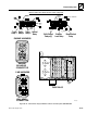
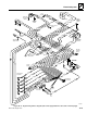
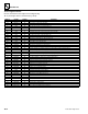
10.4.3 Cab Harness, S/N 9399 and After
Use this chart for vehicles with S/N 9399 and after.
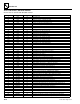
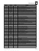
WIRE No. COLOR GAUGE FUNCTION
2 BLK 16 Generic Ground
2B BLK 16 Hourmeter to Ground Splice 40
2C BLK 16 Shift Control Relays to Cab Ground Stud
2D BLK 16 Fuel Level Sender to Ground Splice 50
2E BLK 14 Joystick Logic Board to Ground Splice 40
2F BLK 16 Steer Select Lamp (Terminal 7) to Ground Splice 40
2G BLK 16 Display Panel to Ground Splice 40
2H BLK 16 Display Panel to Ground Splice 40
2J BLK 16 Boom Function Solenoids to Ground Splice 35
2K BLK 10 Ground Splice 45 to Ground Splice 50
2S BLK 16 Seat Belt Switch to Ground Splice 50
2T BLK 16 Backup Alarm to Ground Splice 35
2U BLK 16 Ground Splice 40 to Park Brake Lamp (Terminal 7)
2V BLK 12 Ground Splice 40 to Cab Ground Stud
2Y BLK 10 Ground Splice 35 to Ground Splice 50
2AA BLK 10 Ground Splice 50 to Cab Ground Stud
2BB BLK 10 Ground Jumper for Neutral Relay
2CC BLK 16 Ground Splice 40 to Stabil-TRAK Relays
2EE BLK 16 Ground Splice 35 to Stabil-TRAK Solenoid #5
2FF BLK 16 Ground Splice 35 to Stabil-TRAK Solenoid #4
2GG BLK 16 Ground Splice 35 to Stabil-TRAK Solenoid #3
2HH BLK 16 Ground Splice 35 to Stabil-TRAK Solenoid #2
2JJ BLK 16 Ground Splice 35 to Stabil-TRAK Solenoid #1
2KK BLK 16 Ground Splice 35 to Boom Proximity Switch
2LL BLK 16 Ground Splice 40 to Relay 1
2MM BLK 16 Ground Splice 40 to Neutral Relay
3 RED 10 Starter (+) Power to (+) Grid (fuse panel bus)
4 YEL/BLU 16 Neutral Relay (Terminal 87) to Starter Relay (coil positive terminal)
5 YEL/RED 14 Ignition Switch (Terminal 2) to Switched Grid (fuse panel bus)
6 ORN 10 Ignition Switch to 30-amp Main Fuse
7 BRN 10 Ignition Switch (Terminal 4) to (+) Grid (fuse panel bus)
7A BRN/WHT 10 Closed Cab Relay (Terminal 85) to Splice 65
8 PNK 16 7.5-amp Fuse to Park Brake Switch (Terminal 5)
9 RED/WHT 16 Park Brake Switch (Terminal 6) to Neutral Relay (Terminal 30)
10 PNK/GRN 16 Alternator Indicator Terminal to CUMMINS Input (10GY/D)
10A PNK/GRN 16 Alternator Indicator Terminal to PERKINS Input (10GY/F)
11 PUR/WHT 16 Oil Pressure Input (Terminal 10/C) to Oil Pressure Switch (Terminal A)
12 RED/BLU 16 Water Temperature Logic (10/B) to Water Temperature Switch
14 WHT/BRN 16 Hydraulic Oil Temperature Logic (10GY/A) to Hydraulic Oil Temperature Switch
15 DK GRN 16 Ignition Switch (Terminal 3) to 7.5-amp Fuse
16 WHT/ORN 16 7.5-amp Fuse to Park Brake Switch (Terminal 2)
17 PNK/WHT 16 7.5-amp Fuse to Steer Select Switch (Terminal 2)
18 GRY/GRN 16 Steer Select Switch (Terminal 1) to Steer Select Solenoid (Terminal 4)
19 YEL/BLK 16 Steer Select Switch (Terminal 3) to Steer Select Solenoid (Terminal 4)
19A YEL/BLK 16 Steer Select Switch (Terminal 3) to Steer Select Logic (Terminal 6/E)
20 BRN/YEL 14 7.5-amp Fuse to Shift Control Switch (Terminal 8)
21 YEL/BLU 16 Reverse Relay (Terminal 87) to Reverse Clutch Solenoid
22 DK GRN/WHT 16 Splice 20 to Reverse Alarm
23 RED/GRY 16 Forward Relay (Terminal 87) to Forward Clutch Solenoid
24 ORN/BLU 16 Transmission Relay 3 (Terminal 87) to Shuttle Clutch Solenoid
24A ORN/BLU 16 Splice 80 to Fourth Gear (optional--if equipped) Input (Terminal 6/C)
25 LT BLU 16 Transmission Shift Control Switch (through Splice 60) to 1st Clutch Solenoid