
Service Manual User Manual

Section 9
9-58
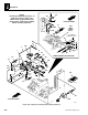
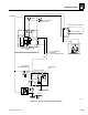
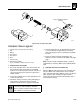
Figure 9– 45. Valve plate assembly (with auxiliary hydraulics)
NOTE:
The Auxiliary Hydraulic System is an
option that consists of the parts
shown on this page PLUS the parts
shown on the “ Valve plate assembly
without auxiliary hydraulics”
Front Of Vehicle
Front Of Vehicle
17
18
15
12
13
10
11
6
9
8
15
17
16
17
7
14
1
21
22
11
2
17
18
3
5
3
15
13
4
16
8
7
14
20
9
17
13
15
10
18
29
PF0760
PS0550
REAR VIEW OF VALVE PLATE
See
“ Main
Control
Valve”
6
19
14
23
24
Remove
Plug
25
26
27
28
19
To Stabilizer
Cylinder Port “T”
Model 3606 • Origin 10/99