
Service Manual User Manual

Hydraulic System
9-35
Model 3606 • Origin 10/99
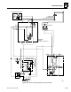
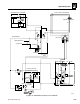
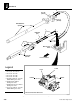
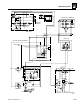
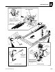
Figure 9– 24. Frame tilt and stabilizer components.
FTB
FTR
PH0940
38
2
4
4
5
4
5
5
6
6
7
8
5
6
7
8
7
8
7
8
9
9
10
11
12
13
12
13
14
15
16
17
18
19
17
20
21
22
23
24
25
26
27
28
29
30
31
31
33
34
35
36
37
38
39
40
41
35
MS0460
42
4
3
32
33
35
34
6
Main Control Valve
(ref.)
NOTE:
With optional Aux.
Hydraulics, a tee replaces the
90° elbow (see item 17).
REAR VIEW
Front of Vehicle
Apply Loctite to
item 14 and
torque to
37 lb/ft (50 Nm)
Frame Tilt Cylinder
Stabilizer Cylinder
Apply Loctite
to items 15
and 24
Torque to
37 lb/ft (50 Nm)