
Installation Guide


REV.3/19-05 Page 11 of 16
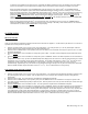
WIRING THE FLAME CONTROLLER
Connect the two ORANGE 18-gauge wires from the remote receiver to
the spade terminals on the flame controller. It does not matter which
wire goes to the terminal. The input voltage to the flame controller has
been changed from 24VAC to 24VDC within the remote.
CAUTION
: DO NOT ATTACH WIRES FROM THE FLAME
CONTROLLER TERMINALS TO THE TERMINAL BLOCK ON THE GAS
VALVE. THE FLAME CONTROLLER TERMINALS HAVE AN OUTPUT
OF 24VDC AND WILL BURN OUT THE MILLIVOLT VALVE.
WIRING A FAN/BLOWER
NOTE
: When connecting wires to the fan terminal, make sure the 110VAC power
to the fan has been turned off!
Fireplace systems with a factory-installed fan or blower will include an ON/OFF switch
leading from the power source to the fan/blower. Remove the two wires leading to the
terminals on this switch and instead connect the two BLUE wires from the remote
receiver to these two wires. Either wire from the remote receiver goes to either power
source female wire terminal. Be sure these wires are positioned in the coolest pathway
leading from the switch to the remote receiver.
This remote control system is designed to control the fan motor to either ON or OFF.
It will not operate a 3-speed variable speed controller other than to turn it OFF or ON
at whatever position the switch or controller is set. If your fireplace system has a 3-speed
or variable speed fan and you wish to remotely control it ON/OFF, attach the two BLUE
wires from the remote receiver to the “hot” power leg leading to the variable speed switch.
The speed selection switch will still be operational, however, the receiver will only operate
the fan/blower ON/ OFF at the current setting of the speed controller. Additional wire
terminals are required to make a multi-speed fan operate, or, the power line leading to the
fan switch can be spliced into, allowing operation of the multi-speed functions at the switch.
CAUTION:
All wiring should be done by a qualified electrician and shall be in compliance with local codes and with the National
Electric Code ANSI/NFPA No. 70- current ( in the United States), or with the current CSA C22.1 Canadian Code ( in Canada).
OPERATING SAFETY MONITORS
– SYSTEM SHUTDOWN
THERMO- SAFETY FEATURE – RECEIVER (T/S –RX)
This SKYTECH remote control has a THERMO- SAFETY feature that is built into the system’s RECEIVER. This feature is
temperature- activated and provides an extra margin of safety when the RECEIVER is operating where ambient temperatures exceed
130 degrees inside the receiver case.
The THERMO-SAFETY feature, in the RECEIVER, operates in the following manner, when the fireplace is in operation.
The receiver is thermally protected from extreme heat conditions. Heat can have a negative effect on the operation of the
receiver’s microprocessors.
The receiver’s THERMO-SAFETY operation is controlled by a “resetable” THERMISTOR that shuts down the fireplace when
the ambient temperature, inside the receiver case, exceeds 130
0
F. This is especially important when the receiver is in the
THERMO mode, and the fireplace is cycling ON and OFF, automatically. Should the homeowner be away from the home and
1 2 3 4 5 6
to 24VAC
input
REMOTE RECEIVER
Plunger
Jam Nut
3 VDC “Pulse”
Latching
Solenoid
Regulator
Body
FAN
Fan Contro Switch (Hot)
(remove wires from fan
switch terminals)
AC power to fan/blower
Hot (+)
Neutral (-)
1 2 3 4 5 6
to 24VAC
input
REMOTE RECEIVER
DO NO CONNECT 110VAC TO WIRES
LEADING TO THE REMOTE RECEIVER