
Installation Guide

REV. 3/19/05 Page 9 of 14
LEARN
110VAC
OFF-REMOTE-ON
GROUND
FAN
VALVE
LEARN
OFF-REMOTE-ON
GROUND
FAN
VALVE
REMOTE
RECEIVER
TERMINAL BLOCK
ON MILLIVOLT
GAS VALVES
TH
TP
TP
TH
THERMOPILE/
PILOT LIGHT
LEARN
OFF-REMOTE-ON
GROUND
FAN
VALVE
REMOTE
RECEIVER
ELECTRONIC MODULE
TR
TH
neutral wire
24VAC
hot wire
120VAC
110/24VAC
Transformer
LEARN
OFF-REMOTE-ON
GROUND
FAN
VALVE
REMOTE
RECEIVER
(Receptacle on back)
Line cord
from fan
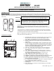
LOCATING RECEIVER AND OPERATING FUNCTIONS
The remote receiver can be positioned under the firebox in the control compartment of the fireplace if ambient temperatures do not exceed 120
Degrees F. The remote receiver accepts commands from the transmitter and is capable of remotely operating several separate circuit functions.
This system is designed to control the following components:
WIRE COLORS
Gas Valve (Red wires) -Millivolt or electronic ignition
Fan/Blower (Blue wires) -110 VAC plug-in or in-line ON/OFF switch
NOTE: remote receiver will only respond to the transmitter when the 3-position
slide button on the remote receiver is in the REMOTE position. If the system
does not respond to the transmitter on initial use, see section, MATCHING
SECURITY CODES.
WIRING INSTRUCTIONS
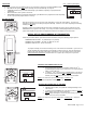
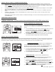
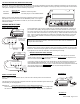
WIRING MILLIVOLT VALVES
The terminal block on the receiver includes two 1/4” terminals marked VALVE. Using two, 18
ga. stranded wires (RED), with appropriate insulated connectors attached to each end, plug
one end of each wire into one of the two terminals marked VALVE on the remote receiver, and
connect the other ends of these wires to the (1) TH and (1) TH/TP terminals located on the gas
valve. It does not matter which wires go to which set of terminals at the receiver or at the gas
valve. This is a DRY CONTACT circuit and no power is provided to these terminals by the
remote receiver.
Operation of the remote receiver is similar to that of a thermostat in that both turn the gas valve
on and off. A thermostat’s input signals are from different temperatures. The remote receiver’s
input signals are sent from the transmitter, either manually or thermally.
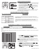
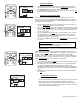
WIRING ELECTRONIC SPARK IGNITION
The remote receiver can be connected to a 24VAC transformer that operates an electronic
ignition module, using the same
VALVE terminals on the remote receiver to complete the 24
VAC circuit to the electronic ignition module.
Connect the neutral wire from the 24 VAC transformer to the TR (transformer) terminal on the
ELECTRONIC IGNITION MODULE. Connect the hot wire from the 24 VAC transformer to
either VALVE terminal on the remote receiver
. Connect another same-gauge wire between the
other VALVE terminal on the remote receiver
to the TH (thermostat) terminal on the
ELECTRONIC IGNITION MODULE.
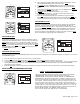
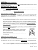
METHOD #1
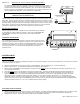
WIRING A FAN/BLOWER
NOTE: When connecting wires to the fan, make sure the 110VAC power to the fan has been
turned off!
This SKYTECH receiver provides 2 separate methods to operate a fan/blower system that may be
included with your heating appliance.
METHOD #1 PLUG FAN CORD DIRECTLY INTO REMOTE RECEIVER
On the backside of the receiver, the fan’s 2-prong or 3-prong power cord can be plugged into
the receiver’s receptacle. This receptacle provides 110/120 – 5AMP power for a fan/blower.
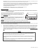
METHOD #2
NOTE: Some gas valves are polarized. If the remote receiver’s ON/REMOTE/OFF
functions don’t operate the gas valve, reverse the receiver wires at the TH transmitter on
the gas valve terminal block.