
Installation Guide

REV. 3/19/05 Page 10 of 14
LEARN
OFF-REMOTE-ON
GROUND
FAN
VALVE
REMOTE
RECEIVER
FAN
Fan Contro Switch (Hot)
(remove wires from fan
switch terminals)
AC power to fan/blower
Hot (+)
Neutral (-)
LEARN
110VAC
OFF-REMOTE-ON
GROUND
FAN
VALVE
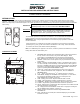
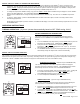
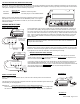
METHOD #2 WIRE FAN LINE TO DRY CONTACT RECEIVER TERMINALS
For fan/blower systems that are “hard wired” directly to the appliance’s internal J-BOX, and
use an in-line switch to control the fan/blower. The front of the receiver includes two 1/4”
terminals that are controlled by a “DRY CONTACT” relay. These two terminals DO NOT
provide any power to the fan/blower, they only complete a “dry contact” circuit between the
“hot” leg leading to the fan/blower. These terminals are marked FAN.
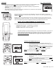
The SKYTECH receiver in this remote control system is designed to control the fan motor to either
ON or OFF. It will not operate a 3-speed or variable controller other than to turn it OFF or ON at
whatever position the switch or controller is set. If the fireplace system has a 3-speed or variable
speed fan and you wish to remotely control it ON/OFF, attach two wires from the remote receiver
to this switch. The speed selection switch will be operational, however, the receiver will only
operate the fan/blower ON or OFF at the current setting of the speed controller.
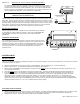
DRY CONTACT TERMINALS
There may be other sets of 1/4” terminals on the receiver which may be available
for controlling other “DRY CONTACT” functions. Refer to the SUPPLEMENTAL
DRY CONTACT instruction sheet for operation of these “DRY CONTACT”
TERMINALS.
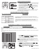
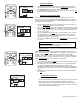
GROUNDING THE RECEIVER
The terminal block on the receiver includes a 1/4” male terminal and a 1/4” screw
that can be used to ground the fan/blower or appliance to the 110/120 VAC circuit
powering the receiver. These connectors are marked GROUND. Using an 18
ga. Wire, usually GREEN in color, attach the grounding wire to the 1/4” terminal
on the remote receiver. You may also attach the grounding wire under the
grounding screw.
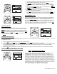
SYSTEM CHECK
MILLIVOLT VALVES
Light your gas appliance following the lighting instructions that came with the appliance. Confirm that the pilot flame is on; it must be in operation
for the main gas valve to operate.
1. Slide the 3-position button on the remote receiver to the ON position. The main gas flame (i.e., the fire) should ignite.
2. Slide the button to OFF. The flame should extinguish (the pilot flame will remain on).
3. Slide the button to REMOTE (the center position), and then press the MODE
button on the transmitter to change the system to ON. The
main gas flame should ignite.
4. Press the MODE
button on the transmitter to change the system to OFF. The flame should extinguish (the pilot flame will remain on).
5. Press the MODE
button on the transmitter to change the system to THERMO. Advance the SET temperature on the transmitter to a
temperature of a least 2
0
F (1
0
C) above the ROOM temperature displayed on the LCD screen. With this manual setting, the normal
thermostatic cycle is overridden and the system flame will ignite. Set the SET temperature to at least 2
0
F (1
0
C) below the room
temperature and the system flame will extinguish in a few seconds. Thereafter, it should continue to cycle to on and off thermostatically
approximately every two minutes as the ROOM temperature changes, but only when the temperature differential between ROOM and SET
temperatures differ at least 2
0
F (1
0
C). The 2
0
F differential is the factory setting.
ELECTRONIC IGNITION SYSTEMS
1. Slide the 3-position button on the remote receiver to the ON position. The spark electrode should begin sparking to ignite the pilot (the pilot
may ignite after only one spark). After the pilot flame is lit, the main gas valve should open and the main gas flame should ignite.
2. Slide the button to OFF. The main gas flame and pilot flame should BOTH extinguish.
CAUTION: DISCONNECT POWER TO FIREPLACE BEFORE
MAKING THIS CONNECTION.