
Instruction Manual

REV. 2-18-22 Page 4
Skytech: 3002
INSTALLATION INSTRUCTIONS
The remote receiver can be Wall Mounted into a standard plastic switch box or (Hearth Mounted) placed on or near the
replace hearth. Determine where you will install the receiver before proceeding. Preferably, the remote receiver should
be wall-mounted in a plastic switch box, as this will protect its electronic components from both the heat produced by the
gas appliance and potential damage or abuse that can occur if it is left exposed on the hearth. PROTECTION FROM
EXTREME HEAT IS VERY IMPORTANT. Like any piece of electronic equipment the receiver should be kept away from
temperatures exceeding 130°F inside the receiver case. Battery life is also signicantly shortened if batteries are exposed
to high temperatures.
When installing the receiver into a switch box ensure the receiver switch is in the OFF position before installation. The
receiver is supplied with 18-inches of wire. If additional wire is required it is recommended that 18 gauge stranded or solid
wires (not included) be used to make connections between the terminal wiring block on the millivolt gas valve or electronic
module and the wire terminals on the remote receiver. For the best results, use 18 gauge stranded or solid wire, splice
into the black wires of the receiver or remove the black wires and install wires directly to the receiver. Be sure no splices
measure longer than 20-feet and allow ample wire to remove the receiver for annual battery replacement.
WALL MOUNTING
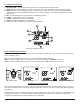
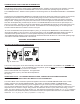
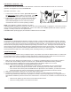
First, install (4) AA-size 1.5 ALKALINE batteries in the remote receiver (Fig 11). For best performance, remote receiver
batteries should be factory fresh when installed. The system operates best when battery output is greater than 5.3 volts.
Four (4) new AA batteries should provide an output voltage of 6.0 to 6.2 volts. Be sure batteries are installed with the
(+) and (-) ends facing the correct direction.
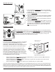
Next, attach wall mount cover plate to receiver box (Fig. 12):
Position the receiver as shown in the diagram to the left with lower tab on wall mount cover plate inserted into groove of
receiver. Move the receiver up and snap into top tab of cover plate.
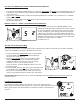
Position the cover plate so the word ON is facing up (Fig. 13); then, install the remote receiver into the plastic switch box
using the two long screws provided. Push the slide button over the receiver slide switch only after making sure the remote
receiver has LEARNED the transmitter’s security code (see LEARNING TRANSMITTER TO RECEIVER).
NOTE: The remote receiver will only respond to the transmitter when the 3-position slide button on the remote receiver is
in the (middle) REMOTE position. If the system does not respond to the battery transmitter on initial use, see LEARNING
TRANSMITTER TO RECEIVER section, and re-check battery positions in the remote receiver.
Remote Receiver
Cover Plate
(Rear View)
Fig. 12 Wall plate to Receiver
REMOTE
O
N
O
F
F
LEARN
WALL
Plastic Switch Box
Remote Receiver
Wall cover plate
& Transmitter holder
Receiver
Slide
Button
Fig. 13 Installing in wall box.
INSTALLATION PRECAUTIONS
This remote control system must be installed exactly as outlined in these instructions. Read all instructions completely
before attempting installation. Follow instructions carefully during installation. Any modications of the SKYTECH
remote control or any of its components will void the warranty and may could cause a re hazard.
Do not connect any gas valve or electronic module directly to 110-120VAC power. Consult gas appliance manufac-
turer’s instructions and wiring schematics for proper placement of all wires. All electronic modules are to be wired to
manufacturer’s specications.
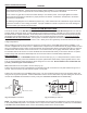
The following wiring diagrams are for illustration purpose only. Follow instructions from manufacturer of gas valve and/
or electronic module for correct wiring procedures. Improper installation of electric components can cause damage to
electronic module, gas valve and remote receiver.
WARNING