
Installation Guide

REV 09/02
Page 3 of 4
WIRING INSTRUCTIONS
WARNING
DO NOT CONNECT REMOTE RECEIVER DIRECTLY TO 110-120 VAC POWER. THIS WILL BURN OUT THE
REMOTE RECEIVER AND THE ELECTRONIC MODULE. CONSULT GAS APPLIANCE MANUFACTURER’S
INSTRUCTIONS AND WIRING SCHEMATICS FOR PROPER PLACEMENT OF ALL WIRES. ALL
ELECTRONIC MODULES ARE TO BE WIRED TO MANUFACTURER’S SPECIFICATIONS
THE DIAGRAMS THAT FOLLOW ARE FOR ILLUSTRATION PURPOSES ONLY. FOLLOW INSTRUCTIONS
FROM MANUFACTURER OF GAS VALVE AND/OR ELECTRONIC MODULE FOR CORRECT WIRING
PROCEDURES. IMPROPER INSTALLATION OF ELECTRIC COMPONENTS CAN CAUSE DAMAGE TO
ELETRONIC MODULE. GAS VALVE, AND REMOTE RECEIVER.
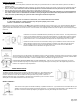
WIRING MILLIVOLT VALVES
Installer must connect two 18 gauge wires from the remote receiver to the TH and TH/TP terminals on the
millivolt gas valve. (It does not matter which receiver wires are connected to the designated terminals listed
above.)
Operation of the remote receiver is similar to a wall switch in that both turn the gas valve on and off. The
remote receiver’s input signals come from the ON/OFF buttons on the transmitter.
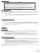
WIRING ELECTRONIC SPARK IGNITIONS
Connect the neutral wire from the 24VAC transformer to the TR (transformer) terminal on the ELECTRONIC
MODULE. Connect the hot wire from the 24VAC transformer to either of the wire terminals on the remote
receiver. Connect another wire (included) between the other receiver wire terminal and the TH (thermostat)
terminal on the ELECTRONIC MODULE.
SYSTEM CHECK
MILLIVOLT VALVES
Light your gas appliance following the lighting instructions that came with the appliance. Confirm that the pilot flame is on; it must be in
operation for the main gas valve to operate.
1. Slide the 3-position button on the remote receiver to the ON position. The main gas flame (i.e., the fire) should ignite.
2. Slide the button to OFF. The flame should extinguish (the pilot flame will remain on).
3. Slide the button to REMOTE (the center position), then press the ON button on the Transmitter or Wall Transmitter. NOTE:
upon initial operation and after an extended period of non-use, the ON button must be pressed for up to three seconds.
4. Press the OFF button on the Transmitter or Wall Transmitter. The flame should extinguish (the pilot flame will remain on).
ELECTRONIC SPARK IGNITION VALVES
1. Slide the 3-position button on the remote receiver to the ON position. The spark electrode should begin sparking to ignite the
pilot (the pilot may ignite after only one spark). After the pilot flame is lit, the main gas valve should open and the main gas flame
should ignite.
2. Slide the button to OFF. The main gas flame and pilot flame should BOTH extinguish.
3. Slide the button to REMOTE (the center position), the press the ON button on the Wall Transmitter. The spark electrode should
begin sparking to ignite the pilot. After the pilot is lit, the main gas valve should open and the main gas flame should ignite.
NOTE: Upon initial operation and after an extended period of non-use, the ON button must be pressed for up to three seconds.
4. Press the OFF button on the Wall Transmitter. The main gas flame and pilot flame should both extinguish.
If you have any problems with operation, recheck your connection and ensure transmitter batteries are fully charged. If no problem is found,
contact the dealer where you purchased your remote control.