
Installation Guide

REV 4/11/05 Page 3 of 4
WIRING INSTRUCTIONS
A qualified electrician or a gas technician who is familiar with the gas appliance and gas valves that will be operated by this remote should
install the remote control system. Incorrect wiring connections WILL cause damage to the gas valve or electronic module operating the gas
appliance and may also damage the remote receiver.
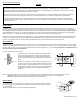
WIRING MILLIVOLT VALVES
The remote receiver is connected to the millivolt valve using the TH (thermostat) terminals on the terminal block on the millivolt gas valve.
Connect 18 gauge solid or stranded wires from the remote receiver to the gas valve.
Operation of the remote receiver is similar to that of a thermostat in that both turn the gas valve on and off
based on input signals. A thermostat’s input signals are different temperatures. The remote receiver’s
input signals come from the transmitter.
Connect each of the two wires leading from the TH terminals on the millivolt gas valve to either of the two
wire terminals on the remote receiver. Normally it does not matter which wires go to which terminal.
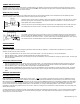
WIRING ELECTRONIC SPARK IGNITIONS
The remote control receiver can be connected, in series, to a 24VAC transformer to the TR (transformer)
terminal on the ELECTRONIC MODULE. Connect the hot wire from the 24VAC transformer to either of
the wire terminals on the remote receiver. Connect another wire (not included) between the other receiver
wire terminal and the TH (thermostat) terminal on the ELECTRONIC MODULE.
SYSTEM CHECK
MILLIVOLT VALVES
Light your gas appliance following the lighting instructions that came with the appliance. Confirm that the pilot flame is on; it must be in
operation for the main gas valve to operate.
• Slide the 3-position button on the remote receiver to the ON position. The main gas flame (i.e., the fire) should ignite.
• Slide the button to OFF. The flame should extinguish (the pilot flame will remain on).
• Slide the button to REMOTE (the center position), then press the ON button on the transmitter to change the system to ON. The main gas
flame should ignite.
ELECTRONIC IGNITION SYSTEMS
• Slide the 3-position button on the remote receiver to the ON position. The spark electrode should begin sparking to ignite the pilot (the
pilot may ignite after only one spark). After the pilot flame is lit, the main gas valve should open and the main gas flame should ignite.
• Slide the button to OFF. The main gas flame and pilot flame should BOTH extinguish.
• Slide the button to REMOTE (the center position), then press the ON button on the transmitter to change the system to ON. The spark
electrode should begin sparking to ignite the pilot. After the pilot is lit, the main gas valve should open and the main gas flame should
ignite.
GENERAL INFORMATION
MATCHING SECURITY CODES
Each transmitter can use one of 65,536 unique security codes. It may
be necessary to program the remote receiver to LEARN the security
code of the transmitter upon initial use
, if batteries are replaced, or if a replacement transmitter is purchased from your dealer or the factory.
When matching security codes, be sure slide button on the receiver is in the REMOTE position; the code will NOT “LEARN” if the slide switch
is in the ON or OFF position. Program the remote receiver to LEARN a new security code by pushing in the LEARN button on the top of the
remote receiver and then pressing the MODE button on the transmitter. A change in the beeping pattern, at the receiver, indicates the
transmitter’s code has been programmed into the receiver. When an existing receiver is matched to a new transmitter, the new security code
will override the old one.
The microprocessor that controls the security code matching procedure is controlled by a timing function. If you are unsuccessful in matching
the security code on the first attempt, wait 1-2 minutes before trying again – this delay allows the microprocessor to reset its timer circuitry –
and try up to two or three more times.
TERMINAL BLOCK
ON MILLIVOLT
GAS VALVES
TH
TP
TP
TH
THERMOPILE/
PILOT LIGHT
REMOTE
RECEIVER
ELECTRONIC MODULE
TR
TH
REMOTE
RECEIVER
neutral wire
24VAC
hot wire
120VAC
110/24VAC
Transformer