
Installation and Operating Instructions

Skytech: 3301
REV. 2-18-22 Page 3
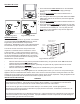
The remote receiver operates on (4) AA-size 1.5V batteries.
It is recommended that ALKALINE batteries be used for
longer battery life and maximum microprocessor
performance. IMPORTANT: New or fully charged batteries
are essential for proper operation of the remote receiver.
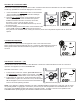
The remote receiver houses the microprocessor that
responds to commands from the transmitter to control
system operation. It emits one beep when it receives an
ON or OFF command manually, but no beep when cycling
on and off automatically in THERMO mode. The remote
receiver has a 3-position slide switch for selecting the ON/
REMOTE/OFF mode of operation:
• With the slide switch in the ON position (toward the LEARN button), the system will remain ON until the slide
switch is placed in the OFF or REMOTE position.
• With the slide switch in the REMOTE position (centered), the system will only operate if the remote receiver
receives commands from the transmitter.
• With the slide switch in the OFF position (away from the LEARN button), the system is OFF.
If you are going to be away from the gas appliance for an extended period of time (i.e. 72 hours or more) where the gas
appliance will be left unattended then slide the switch on the receiver to the OFF position. Placing the switch in the OFF
position serves as a safety “lock-out” rendering the system and the remote receiver inoperative. Most gas appliances are
considered supplemental heat and should not be used as a primary heat source.
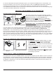
REMOTE RECEIVER
REMOTE
ON
OFF
LEARN
Requires 4-AA 1.5V
alkaline batteries
Learning
button
Remote Receiver
Battery cover slides on/off
Slide
Switch
ON
REMOTE
OFF
Fig. 11 Remote Receiver
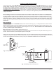
INSTALLATION PRECAUTIONS
This remote control system must be installed exactly as outlined in these instructions. Read all instructions completely
before attempting installation. Follow instructions carefully during installation. Any modications of the SKYTECH
remote control or any of its components will void the warranty and could cause a re hazard.
Do not connect any gas valve or electronic module directly to 110-120VAC power. Consult gas appliance
manufacturer’s instructions and wiring schematics for proper placement of all wires. All electronic modules are to be
wired to manufacturer’s specications.
The following wiring diagrams are for illustration purpose only. Follow instructions from manufacturer of gas valve and/
or electronic module for correct wiring procedures. Improper installation of electric components can cause damage to
electronic module, gas valve and remote receiver.
WARNING
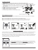
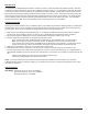
SETTING THE CLOCK
1. Press and hold the TIMER/TIME button on the transmitter
for more than 2-seconds. The hour digit(s) will begin
blinking.
2. Press the UP or DOWN button until the desired hour is
displayed in AM or PM.
3. After setting the desired hour, press and release the TIMER/
TIME button again to set the minutes; the minute digits will
begin blinking.
4. Press the UP or DOWN button until the desired minutes are
displayed.
5. Press and hold the TIMER/TIME button again for more than
2-seconds. The time digits will cease ashing, indicating the
clock has been successfully set. You may also press the
SET button on the transmitter to stop the time digits from
blinking and set the time.
DOWN
UP
MODE
SET
TIME
TIMER
COVER OPEN
Fig. 8 Timer/Time Button
ROOM
SET
ROOM
SET
Fig. 9Setting Hours
Fig. 10 Setting Minutes