
Installation and Operation Instructions


Skytech: 3003
REV. 2-18-22 Page 2
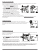
Fig. 3 Mode Button
BASIC TRANSMITTER FUNCTIONS
To operate the transmitter, press and release the MODE button (Fig. 3) until the LCD screen reads OFF in the display
(Fig. 4).
Step 1: Press the MODE button one time to manually turn ON the appliance (Fig. 5).
Step 2: Press the MODE button a second time to put the to put the system in THERMO mode (Fig. 6).
Step 3: Press the MODE button a third time to turn the appliance back OFF again as show in Fig. 4.
Fig. 4 OFF Mode
ROOM
SET
Fig. 5 Manual ON
ROOM
SET
Fig. 6 Thermo Mode
ROOM
SET
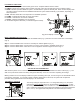
Slide down the plastic cover on the front of the transmitter to expose the “TIMER/TIME” and “SET” buttons (Fig. 1). The
slide cover protects the buttons from being changed accidentally. Close the cover after completing the settings.
Blinking numbers on the LCD display indicate the system is awaiting user input, such as using the UP and DOWN buttons
to program a new setting. If no change is made to ashing digits within 15-seconds, the system will complete the
procedure last programmed and reset the display to its normal state.
SETTING UP THE TRANSMITTER
MODE
UP
DOWN
COVER CLOSED
The factory setting for temperature is ºF. To change this setting to ºC, rst press
and hold the UP and DOWN buttons on the transmitter at the same time. Follow
this same procedure to change from ºC back to ºF. When changing between the ºF
and ºC scales, the temperature in the SET frame defaults to the lowest temperature
(45º F, or 6º C). The highest SET temperature is 99º Fahrenheit (32º Celsius).
SETTING ºF / ºC SCALE
Fig. 7 Temperature Scale
TIMER
TIME
UP
MODE
DOWN
SET
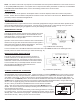
1. BATTERY ICON - Symbol means battery power is low. Replace batteries within 2-weeks.
2. TIMER- Indicates time remaining before system shuts OFF, when timer-programmed; 9-hour maximum setting.
3. MODE- Indicates operation MODE of system. ON indicates the system is manually ON. When screens displays OFF
the entire system is turned OFF and THERMO indicates the system will automatically cycle ON/OFF, depending on
SET temperature.
4. SET- Indicates desire SET room temperature for THERMO operation.
5. FLAME – Indicates burner/valve are in the ON position .
6. CLOCK – Indicates the current time in AM/PM
7. ROOM – Indicates CURRENT room temperature.
8. °F indicates degrees Fahrenheit (°C indicates degrees Celsius).
LCD DISPLAY FUNCTIONS
ROOM
SET
1
2
3
4
5
6
7
8
Fig. 2 LCD Display Functions