Shenzhen SKYSHL Technology Co.,Ltd. Version:V2020.
CATALOGUE 1.Overview……………………………………………… 1 2.Product specifications ………………………………… 1 3.Main components of fusion splicer……………………… 3 4.Common Operating Interface Description ……………… 5 5.Power supply ………………………………………… 6 6.Cleaning operation before splicing ……………………… 8 7.Regular maintenance…………………………………… 9 8.Basic Splicing Procedures …………………………… 11 9.ARC Calibration …………………………………… 14 10.Manually adjust the fiber position……………………15 11.Cutting Length of Optical Fiber……………………… 18 12.
1. Overview Thank you for choosing our products. This operation outline mainly introduces the product performance, basic operation steps and maintenance of optical fiber fusion machine, which is newly produced by our company. The machine adopts a high-speed image processing technology and special precision positioning technology. The whole processes of fiber fusion splicing can be automatically completed within 9 seconds.
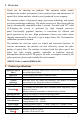
Fiber clamp Heat-shrink sleeve Display ★ External Interface Splicing mode Heater mode Connection storage Electrode life Lithium battery ★ Power saving function Power supply ★ Work environment External dimension★ Weight ★ Multifunctional clamp is applicable to bare fiber, tail fiber, jumper, covered fiber and stealth fiber. The clamp meets the requirement of industry standard FTTH fusion quick splicer.
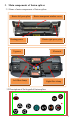
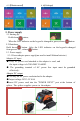
3.Main components of fusion splicer 3.1 Name of main components of fusion splicer Heater left press plate Heating groove Heater transparent window cover Heater right press plate V-groove Left fiber clamp Electrode Right fiber clamp 3.
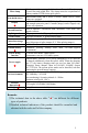
Buttons of keypad I Boutton Buttons of keypad II Readiness Manual mode Automatic mode Parameters menu Power switch Power switch Power switch Power switch Upward movement of fiber Invalid Downward movement of fiber Invalid Leftward movement of fiber Invalid Rightward movement of fiber Invalid Invalid Return to readiness screen Return to readiness screen Invalid Invalid Invalid Enter splice mode menu Open the function to move motor by buttons at pause Continue forward /Start splicing
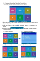
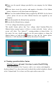
4. Common Operating Interface Description 4.1 Standby Interface of fusion splicer (Level 1 Menu) ●Top right corner of the screen "power adapter". ●Top right corner of the screen current. ●Bottom of screen on current screen. 4.2【Splice options】 4.3【Heater mode】 :Indicating the present power supply mode of :Indicating "Heater" is "warming up" at :Indicating "Keypad operation" 4.2.1【Operation Options】 4.
4.5【Maintenance】 4.6【Settings】 5. Power supply 5.1 Starting up: Hold down button; When the LED indicator on the keypad is changed to green,release button. 5.2 Shutdown: Hold down button. After the LED indicator on the keypad is changed from green to red, release button. 5.3. Power supply 5.3.1 Power adapter power supply(no need to install lithium batteries) Adapter AC input ● Only AC power cord attached to the adapter is used, and the input voltage is AC100-240V 50-60HZ.
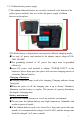
5.3.2 Lithium battery power supply ①The random lithium batteries are correctly connected to the bottom of the splicer (power module), that is to realize the power supply of lithium batteries in the splicer. ②Different battery configurations correspond to different charging modes. ●Use only AC power cord attached to the adapter, input voltage:AC100240V 50/60HZ. ●The grounding terminal of AC power line input must be grounded effectively.
●Please use the special charger provided by our company for the lithium battery. ●Do not short circuit the positive and negative electrodes of the lithium battery, otherwise it will cause burns and explosion. ●Please use the standard lithium battery supplied by SKYSHL for the fusion splicer, please do not use other lithium batteries not supplied by our company. ●Do not disassemble the lithium battery privately. ●Do not hit the lithium battery strongly. 5.3.
●When cleaning, be careful not to bump into or touch the electrode rod. 7. Regular maintenance Cleaning objective lens(SS413F has no mirror, only camera) In routine maintenance, the ear syringe may be used for blowing off the dust from the surface of the mirror and the objective lens of the fusion splicer. The mirror and objective lens are dusty after a long time without routine maintenance, resulting in whitening and fuzzy black-clad of fiber image.
<3> When the lens paper cleaning is invalid and the objective lens surface is free of visible dust particles, try to use a thin cotton swab dipped in a little pure alcohol (99% and above) and wipe gently the lens surface. It is recommended in principle not to use alcohol to clean the mirror surface. <4> Wipe the lens with a cotton swab from the middle of the lens and make a circular motion up to the edges of the lens. Then wipe with a clean dry swab the remaining alcohol.
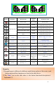
8. Basic Fusion Procedures (Youtube Video:https://youtu.be/A6uZtgps8Ok) 1.Turn on the power of the SS413F 2.Confrimation of splice and heater mode 3.Cleaning coating or tight sleeve of optical fibers "Auto SM" fusion mode is Recommended for SM(G.652& G.657)." Standard 60mm ” heater mode is recommended for the length of protective casing is 60mm. 4.Putting Optical Fiber into thermal shrinkage protection casing 5.Remove the fiber sheath and coating and use alcohol to clean the fiber 6.
12.Place the weld point of the fiber in the center of the heat shrink tube. 13.Move the fiber to place the weld point in the middle of the heat shrink tube. 14.Close the heater cover and start heating Splicing point 15.Complete ●The application of different types of fibers in FTTH projects: ①Open the wind cover and wait for the automatic reset of the fusion splicer until the machine is at readiness status.
250μm bare fiber is connected with the leather cable. the leather cable is connected with the leather cable. SOC hot splicing: The clamp must meet the industry standard FTTH hot melt quick connector.
9. ARC Calibration ( Video: youtu.be/lBO6tsaLN5k) Why do we need to do Arc Calibration? When the fiber optic material, altitude, climate, temperature, humidity, electrode condition and other factors change greatly, it may lead to increased splicing loss of the l splicer; Arc calibration can effectively reduce the splicing loss.It is recommended to do an ARC calibration before the first use after getting the machine.
<5>If it displays “Complete”, it means the calibration was successful. 9. Manually adjust the fiber position / Motor Calibration (Video: youtu.be/u0oUbqNg77A) Why do we need to adjust the position of the fiber? Due to the dust on the construction site, the initial position of the motor changed. When the fiber is welded, the motor stroke cannot reach the alignment position, which leads to the wrong position of the fiber and welding cannot be performed.
<3>Select 【Right Fiber】, Press and hold the screen position(As shown in Figure10.3.2 ). Figure 10.3.1 button to move the fiber to the right Figure 10.3.2 <4>Select 【Left fiber】 and press and hold the or to align the left and right fibers displayed in the X window horizontally(As shown in Figure10.4.2 ). Figure 10.4.1 Figure 10.4.2 <5>Select 【Right fiber】 and press and hold the or to align the left and right fibers displayed in the Y window horizontally(As shown in Figure10.5.2 ). Figure 10.5.
<7>Select【Y Window】,and then press and hold the or to make the center line of the fiber in the Y window overlap the horizontal auxiliary line in the Y window(As shown in Figure10.7.2). Figure 10.7.1 Figure 10.7.2 <8>Select【X Window】, and then press the or key to overlap the center of the gap between the left fiber and the right fiber in X Window with the vertical auxiliary line(As shown in Figure10.8.2). Figure 10.8.1 Figure 10.8.
11. Cutting Length of Optical Fiber optique 12. Common troubleshooting Phenomenon Defect Bubble Reason Measures 1.Clean the fiber. 1.Dust on the end 2.Cut the end face of the fiber of optical fibe. 2. again and make sure the end face Condensation. of the fiber is flat. 3.Poor end face 3.Replace with new electrodes. ofoptical fiber. 4.Stable electrode. 4.Arc intensity is ( 【Maintenance】->【Electrode】 ->【 Stabilize too low. Electrode】) Unfused Variable diameter 1.Too high pre-arc intensity 1.
Phenomenon Defect Reason 1. V-groove is dirty Misalignmen 2. Motor stroke is t of fibers out of range Fiber end bevel angle is too large The end of the fiber has burrs Fiber is not automatically spliced after closing the cover Does not heat up automatically after closing the heating oven cover 2.Manually adjust fiber position. (Video: youtu.be/eoDzTGHLg6w) 1.Poor fiber cut 2. The fiber cleaver blade is worn out, please rotate it to a new position or replace with a new fiber cleaver. (Video: youtu.
Appendix A. Warranty period and conditions (If the following occurs,it is not within the scope of free warranty) ★ The failure or damage caused by the careless use of the operator (Including product physical damage, moisture short-circuit etc.); ★ Product damage caused by the disasters (earthquake, fire, flood, lightning, typhoons, etc.
Maintenance and repair Information required (the following information shall be included in the machine) <1> Full name, Company, Address, Phone number, Fax number and e- mail. <2> Fusion splicer model and serial number. <3> Problems and fault symptom encountered. ①.What time and under what circumstances the problems occur? ②.How is the current situation? ③.The character and image information of optical fiber on the display when the machine fails. <4> List of parts in the machine.