SKB360 -Datasheet SKYLAB M&C Technology Co., Ltd SKB360 Bluetooth 4.0 Low Energy Module User Manual Name: Bluetooth 4.0 Low Energy Module Model No.: SKB360 Version: V2.03 Revision History: Revision Description Approved Date V1.01 Initial Release Sunny 20140611 V2.01 Upgrade hardware Sunny 20150117 V2.02 Added AT instruction Sunny 20150528 V2.
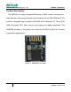
SKYLAB M&C Technology Co., Ltd SKB360 -Datasheet Product Description The SKB360 is a highly integrated Bluetooth 4.0 BLE module, designed for high data rate, short-range wireless communication in the 2.4GHz ISM band. The module is designed base on Nordic nRF51822 radio Transceiver IC, has a 32 bit ARM Cortex-M0 CPU, flash memory and analog and digital peripherals. The SKB360E provides a low power and ultra-low cost BLE solution for wireless transmission applications.
SKYLAB M&C Technology Co., Ltd SKB360 -Datasheet Features Main Chip: nRF51822 Bluetooth® 4.0 low energy single-mode protocol stack L2CAP, ATT, GAP,GATT and SM protocols Central and Peripheral roles GATT Client and Server Full SMP support including MITM and OOB pairing 2.
SKYLAB M&C Technology Co., Ltd SKB360 -Datasheet 20 General Purpose I/O pins SPI Master/Slave Two-wire Master (I2C compatible) UART (CTS/RTS) CPU independent Programmable Peripheral Interconnect (PPI) Quadrature Decoder (QDEC) AES HW encryption Plate antenna Dimension: 17.4x13.7 x1.
SKYLAB M&C Technology Co.
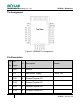
SKB360 -Datasheet SKYLAB M&C Technology Co., Ltd Pin Assignment Figure 2: SKB360 Pin Assignment Pin Description Pin Pin No. name I/O Description 1 GND G Ground 2 VCC P Main power Supply 3 P0.21 I/O General Purpose I/O 4 P0.22 I/O General Purpose I/O 5 P0.23 I/O General Purpose I/O 6 P0.24 I/O General Purpose I/O 6 Remark 1.8V to 3.
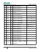
SKB360 -Datasheet SKYLAB M&C Technology Co., Ltd 7 P0.25 I/O General Purpose I/O 8 P0.28 I/O General Purpose I/O 9 P0.29 I/O General Purpose I/O 10 GND G Ground 11 P0.30 I/O General Purpose I/O 12 P0.01 I/O Digital I/O; Analog input ADC/LPCOMP input 2 13 P0.02 I/O Digital I/O; Analog input ADC/LPCOMP input 3 14 P0.03 I/O Digital I/O; Analog input ADC/LPCOMP input 4 15 P0.04 I/O Digital I/O; Analog input ADC/LPCOMP input 5 16 P0.
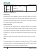
SKB360 -Datasheet SKYLAB M&C Technology Co., Ltd SWDIO/ 25 Hardware debug ;Flash program I/O; nRESET System reset (active low) Interfaces Configuration Power Supply Regulated power for the SKB360I is required. The input voltage Vcc should be 1.8V to 3.6V range, current is no less than 50mA. Suitable decoupling must be provided by external decoupling circuitry (10uF and 1uF). It can reduce the Noise from power supply and increase power stability.
SKYLAB M&C Technology Co.
SKB360 -Datasheet SKYLAB M&C Technology Co., Ltd Serial Peripheral Interface(SPI/SPIS) The SPI interfaces enable full duplex synchronous communication between devices. They support a three-wire (SCK, MISO, MOSI) bi-directional bus with fast data transfers. The SPI Master can communicate with multiple slaves using individual chip select signals for each of the slave devices attached to a bus. Control of chip select signals is left to the application through use of GPIO signals.
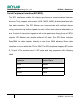
SKB360 -Datasheet SKYLAB M&C Technology Co., Ltd Two-wire Interface(TWI) The two-wire interface can communicate with a bi-directional wired-AND bus with two lines (SCL, SDA). The protocol makes it possible to interconnect up to 127 individually addressable devices. The interface is capable of clock stretching, supporting data rates of 100 kbps and 400 kbps. The module have 2 TWI ports and they properties like following table.
SKB360 -Datasheet SKYLAB M&C Technology Co., Ltd Operating Conditions The operating conditions are the physical parameters that the module can operate within as defined in table Parameter Symbol Min. Typ. Max. Units Supply voltage, normal mode VCC 1.8 3.0 3.6 V Supply rise time (0V to VCC) Tr_vcc 100 ms 75 °C Operating temperature Ta -25 25 General Purpose I/O(GPIO) specifications Parameter Symbol Min. Input high voltage VIH Input low voltage Typ . Max. Units 0.
SKB360 -Datasheet SKYLAB M&C Technology Co., Ltd Absolute Maximum Rating Maximum ratings are the extreme limits the module can be exposed to without causing permanent damage. Exposure to absolute maximum ratings for prolonged periods of time may affect the reliability of the module. Parameter Symbol Min Max Units VCC -0.3 +3.9 V VIO -0.3 Power Supply Power Supply Volt. I/0 Pin voltage Input voltage on any input VCC+0.
SKYLAB M&C Technology Co.
SKYLAB M&C Technology Co.
SKB360 -Datasheet SKYLAB M&C Technology Co., Ltd Manufacturing Process Recommendations Figure 6: SKB360 Typical Leadfree Soldering Profile Note : The final soldering temperature chosen at the factory depends on additional external factors like choice of soldering paste , size , thickness and properties of the baseboard , etc. Exceeding the maximum soldering temperature in the recommended soldering profile may permanently damage the module.
SKYLAB M&C Technology Co., Ltd SKB360 -Datasheet Packaging Specification SKB360 modules are shipped in reel and with 660 units per reel. Each tray is ‘dry’ package.
SKYLAB M&C Technology Co., Ltd SKB360 -Datasheet FCC Statement Changes or modifications not expressly approved by the party responsible for compliance could void the user's authority to operate the equipment. This equipment has been tested and found to comply with the limits for a Class B digital device, pursuant to Part 15 of the FCC Rules. These limits are designed to provide reasonable protection against harmful interference in a residential installation.
SKYLAB M&C Technology Co., Ltd SKB360E-Datasheet Skylab M&C Technology Co., Ltd. FCC Radiation Exposure Statement The modular can be installed or integrated in mobile or fix devices only. This modular cannot be installed in any portable device, for example, USB dongle like transmitters is forbidden. This modular complies with FCC RF radiation exposure limits set forth for an uncontrolled environment.