INSTRUCTION MANUAL Telescopes with NEQ3 & EQ5 Mount 031007V3
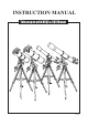
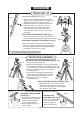
REFRACTOR NEQ3 B C D H A EQ5 E G F 11 10 L 1 2 9 3 4 5 D E 8 7 G 6 H F 12 11(150mm/1200mm) 10 9 8 7 6 5 I a b EQ3-2 A. Dust Cap/Mask B. C. D. E. F. G. H. I. J. K. L. B C I J K A (Remove before Viewing) Sun Shade Objective Lens Telescope Main Body Piggyback Bracket Finderscope Finderscope Bracket Alignment Screw Eyepiece Diagonal Focus Tube Focus Knob 1. R.A. Flexible Control Cable 2. Dec. Flexible Control Cable 3. R.A. Lock knob 4. Polarscope Holder (not shown) 5.
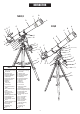
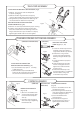
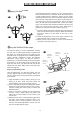
REFLECTOR NEQ3 C D B E F G A EQ5 H I J C B F A 10 9 G H I 8 1 7 6 5 4 2 3 8 b 7 6 EQ3-2 A. Dust Cap/Mask (Remove before Viewing) F. G. H. I. J. J 12 11 10 9 a B. C. D. E. D E Focus Tube Finderscope Finderscope Bracket Finderscope Adjustment Screws Eyepiece Focus Knob Piggyback Bracket Telescope Main Body Primary Mirror Position 1. Dec. Flexible Control Cable 2. R.A. Lock Knob 3. Polarscope Holder (not shown) 4. Altitude Adjustment T-bolts 5. Counterweight Rod 6. Counterweight 7.
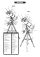
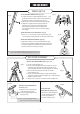
MAKSUTOV NEQ3 A B C D 9 8 E F 1 2 7 3 6 4 5 a b c A. Dust Cap (not shown, remove before Viewing) B. C. D. E. F. Red Dot Finder Focus Locking Screw Eyepiece Diagonal Focusing Knob 1. R.A Lock Knob 2. Dec Flexible Control Cable 3. Polarscope Holder/ Polarscope (not shown, optional) 4. Altitude Adjustment T-bolt 5. Azimuth Adjustment Knobs 6. Counterweight Locking Thumb Screw 7. Counterweight Rod 8. Dec Lock Knob 9. Dec Setting Circle a. Tripod Leg b.
TABLE OF CONTENTS Assembling Your Telescope 6 For NEQ3 Tripod Set up Telescope Assembly Finderscope/Red Dot Finder Assembly Eyepiece Assembly 6 6 7 7 For EQ5 Tripod Set up Telescope Assembly Finderscope Assembly Eyepiece Assembly 8 8 9 9 Operating Your Telescope Aligning the Finderscope Using the Red Dot Finder Balancing the telescope Using the leveling bubble Operating the NEQ3 Mount Operating the EQ5 Mount Using the Barlow Lens Focusing Polar Alignment for visual use Pointing your telescope Using th
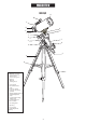
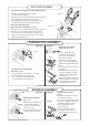
FOR NEQ3 MOUNT TRIPOD SET UP Fig. 1 ADJUSTING THE TRIPOD LEGS (Fig.18) Fig. 2 1) Slowly loosen the height adjustment clamp and gently pull out the lower section of each tripod leg. Tighten the clamps to hold the legs in place. 2) Spread the legs apart to stand the tripod upright. 3) Adjust the height of each tripod leg until the tripod head is properly leveled. Note that the tripod legs may not be at same length when the equatorial mount is level. Do not over tighten the clamps.
TELESCOPE ASSEMBLY ATTACHING THE TUBE RINGS TO THE MOUNT (Fig.9) 1) Remove the telescope tube assembly from its plastic packaging. 2) Remove the tube rings from the telescope by releasing their thumb nuts and opening their hinges. 3) Using the bolts provided, fasten the tube rings to the mount with the 10mm wrench provided. Fig.9 ATTACHING THE TELESCOPE MAIN TUBE TO THE TUBE RINGS (Fig.10) Fig.10 1) Remove the telescope tube from the paper covering. 2) Find the center of balance of the telescope tube.
FOR EQ5 MOUNT TRIPOD SET UP Fig.18 ADJUSTING THE TRIPOD LEGS (Fig.18) Fig.19 1) Slowly loosen the height adjustment clamp and gently pull out the lower section of each tripod leg. Tighten the clamps to hold the legs in place. 2) Spread the legs apart to stand the tripod upright. 3) Adjust the height of each tripod leg until the tripod head is properly leveled. Note that the tripod legs may not be at same length when the equatorial mount is level. Do not over tighten the clamps.
TELESCOPE ASSEMBLY ATTACHING THE TUBE RINGS TO THE MOUNT(Fig.25) 1) Remove the telescope tube assembly from its plastic packaging. 2) Remove the tube rings from the telescope by releasing their thumb nuts and opening their hinges. 3) Using the bolts provided, fasten the tube rings to the mount with the 10mm wrench provided. ATTACHING THE TELESCOPE MAIN TUBE TO THE TUBE RINGS (Fig.26) Fig.25 Fig.26 1) Remove the telescope tube from the paper covering. 2) Find the center of balance of the telescope tube.
OPERATING YOUR TELESCOPE A ligning the finderscope Fig.a Fig.a1 The finderscope (optical or red dot) is a very useful accessory that is included with your telescope. When the finderscope is correctly aligned with the telescope, objects can be quickly located and brought to the centre of the field. Alignment is best done outdoors in day light when it's easier to locate objects. If it is necessary to refocus your finderscope, sight on an object that is at least 500 yards (metres) away.
B alancing the telescope A Telescope should be balanced before each observing session. Balancing reduces stress on the telescope mount and allows precise control of micro-adjustment. A balanced telescope is specially critical when using the optional clock drive for astrophotography. The telescope should be balanced after all accessories (eyepiece, camera, etc.) have been attached. Before balancing your telescope, make sure that your tripod is balanced and on a stable surface.
Fig.e O perating the NEQ3 mount The NEQ3 mount has controls for both conventional altitude (up-down) and azimuth (left-right) directions of motion. These two adjustments are suggested for large direction changes and for terrestrial viewing. The two azimuth adjustment knobs located near the tripod head allow fine-adjustment of azimuth for polar alignment. Use the altitude adjustment T-bolts for altitude adjustments. These allow fine-adjustment for setting the mount to your local latitude. (Fig.e).
U sing the Barlow lens (optional) Fig.g Eyepiece Barlow A Barlow is a negative lens which increases the magnifying power of an eyepiece, while reducing the field of view. It expands the cone of the focussed light before it reaches the focal point, so that the telescope's focal length appears longer to the eyepiece.
Fig.m You aim your telescope by rotating it along the RA and Dec axes of your mount. In the upper image the telescope is in the HOME position, aimed due north. The side images show the telescope pointing NE (right side) and SW (left side). The bottom image shows the telescope pointing due south. After pointing at an object and tracking it for a while you may find the counterweight(s) rise above the point of being parallel to the ground. If so, it is time to perform a meridian flip.
U sing the Setting Circles The Dec axis is for north/south positions. It is primarily used for finding objects, not for tracking them. It is normal, however, to make occasional adjustments to the Dec axis as well. The better your polar alignment, the fewer Dec adjustments you will need to make. 4 2 0 10 8 6 4 20 3 21 2 22 1 23 10 9 All objects in the sky have assigned coordinates labeled Right Ascension (RA for short) and Declination (Dec for short).
Vega has the coordinates RA 18h 37m. With Vega centered in your eyepiece loosen the RA setting circle setscrew and rotate the scale until it reads 18h 36m. (If you are in the Northern hemisphere use the top row of numbers. If you are in the Southern hemisphere use the lower set of numbers.) To do this turn the RA dial until 18 is lined up with the indicator. The small divisions are set at 10 minutes each, so rotate another 3 divisions past 18h in the direction of 19h. This puts you at 18h 30m.
C hoosing the appropriate eyepiece Calculating the magnification (power) The magnification produced by a telescope is determined by the focal length of the eyepiece that is used with it. To determine a magnification for your telescope, divide its focal length by the focal length of the eyepieces you are going to use. For example, a 10mm focal length eyepiece will give 80X magnification with an 800mm focal length telescope.
OBSERVING THE SKY S ky conditions Sky conditions are usually defined by two atmospheric characteristics, seeing, or the steadiness of the air, and transparency, light scattering due to the amount of water vapour and particulate material in the air. When you observe the Moon and the planets, and they appear as though water is running over them, you probably have bad "seeing" because you are observing through turbulent air.
PROPER CARE FOR YOUR TELESCOPE Collimating a Newtonian reflector Collimation is the process of aligning the mirrors of your telescope so that they work in concert with each other to deliver properly focused light to your eyepiece. By observing out-of-focus star images, you can test whether your telescope's optics are aligned. Place a star in the centre of the field of view and move the focuser so that the image is slightly out of focus.
alternately loosen one and then compensate for the slack by tightening the other two. Stop when you see all three mirror clips (Fig.q-4). Make sure that all three small alignment screws are tightened to secure the secondary mirror in place. Aligning the Primary Mirror Find the three locking screws at the back of your telescope and loosen them by a few turns.
Collimating a refractor with the adjustable objective-lens cell Collimation is the process of aligning the lenses of your telescope so that the light they collect will focus at the right spot at the back of your telescope for your eyepieces to work. Fig.r Collimation is a simple process and works like this: Pull off the dew cap at the front of your telescope and look into the scope. The pair of lenses are held in a cell by a threaded ring.
APPENDIX A - PRECISE POLAR ALIGNMENT FOR NORTHERN HEMISPHERE When your equatorial mount is polar-aligned it is able track the sky easily and hold targets in the eyepiece with just occasional adjustments to the RA control cable. If your mount is motorized it can hold objects in the eyepiece almost indefinitely. An accurate polar alignment also greatly reduces the number of guiding corrections that are needed during long exposure astrophotography.
SIMPLIFIED POLAR ALIGNMENT PROCEDURES The NEQ3 and EQ5 mounts have specially designed reticule patterns and simplified procedures to make polar aligning your mount very simple. In fact, if you purchased a SynScan equipped mount you can perform an extremely accurate polar alignment in less than two minutes! See the SynScan User manual for details. If you do not have a SynScan mount you can still get a very good alignment without much bother. The two simple procedures detailed below work equally well.
APPENDIX B - OPTIONAL ACCESSORIES NEQ3 & EQ5 SYNSCAN Sky-Watcher offers simple solutions for users who would like to attach their smaller telescope to a convenient computerized system but do not wish to deal with the weight of the HEQ5 or EQ6 mount. The NEQ3 and EQ5 SynScan mounts use the same Go-To system found in the HEQ5 and EQ6 Pro mounts. It allows you to point the telescope at a specific object or even tour the skies at the touch of a button.
APPENDIX C - RECOMMENDED READING A mateur Astronomy A stro-photography Beginner's Guide to Amateur Astronomy: An Owner's Manual for the Night Sky by David J. Eicher and, Michael Emmerich (Kalmbach Publishing Co., Books Division, Waukesha, WI, 1993). The Great Atlas of the Stars by Serge Brunier, Constellation photography by Akira Fujii (Firefly Books; Willowdale, ON, Canada 2001). A Manual Of Advanced Celestial Photography by Brad D. Wallis and Robert W.
EQ5 SynScan INSTALLATION Power Cord CONTENTS Hand Control Motor Cables Hand Control Cable Hand Control Holder Hand Controller Motor Controller holder DC 12V Auto Guide Fig.2 Fig.1 Motor Controller SETTING UP 1) Locate the hand control holder. Slide the holder onto the accessory tray as shown in Fig.1. 2) Point the mount to the North, or South in the Southern Hemisphere. Clip the motor controller holder onto the leg that's on the right hand side of the mount, as seen in Fig.2.
INSTRUCTION MANUAL SynScan TM 140303V4 Copyright © Sky-Watcher
Basic Operations CONTENT PART VIII : AUXILIARY FUNCTIONS PART I : INTRODUCTION 1.1 1.2 1.3 1.4 Outline and Interface .......................................................................................... 4 Connecting to a Telescope Mount ...................................................................... 4 Slew the Mount with the Direction Keys .............................................................. 4 SynScan Hand control’s Operating Modes ...................................................
PART I : INTRODUCTION PART I: INTRODUCTION • 1.1 Outline and Interface A SynScan hand control and its interfaces are shown in Fig. 1.1 LCD Display Screen: It can display two lines of text, 18 characters per line. The contrast and the brightness of the red backlight are adjustable. • • The left and right keys are used to control the movements of the Right Ascension (R.A.) axis (for an equatorial mount) or the azimuth axis (for an Alt-azimuth mount).
PART II : INITIALIZATION PART I: INTRODUCTION In Full Feature mode, the hand control must connect to a Sky-Watcher telescope mount. After turning on the power to the mount, the hand control must complete an “Initialization” routine, followed by an “Alignment” routine which establishes a model to transform the coordinates of the mount and the coordinates of the sky. Only after the “Alignment” is done can the SynScan hand control’s high precsion “GOTO” function be used to locate a celestial object.
PART II: INITIALIZATION PART II: INITIALIZATION 3. Warning Message Confirmation The hand control will display a warning message about the dangers of viewing the sun with a telescope. • Press ENTER to confirm you have read the warning messages and proceed to the next step. Press ESC to return to the previous (firmware version display) step. • Users can slew the mount with direction keys in this step. 4.
PART III : ALIGNMENT 3.1 Choosing an Alignment Method At the beginning of the alignment process, users are asked to choose an alignment method. The available alignment methods differ between the mount types, as listed below: • For an equatorial mount: 1-Start Alignment (1-Star Align.), 2-Star Alignment (2-Star Align.) or 3-Star Alignment (3-Star Align.) • For an alt-azimuth mount: Brightest Star Alignment (Brightest Star) or 2-Star Alignment (2-Star Align.
PART III : ALIGNMENT PART III : ALIGNMENT 4. Now the screen will display “Point scope to RR ZZ.Z’ TT.T’ ”, which means point the telescope to RR region, the exact azimuth is ZZ.Z degree and the exact altitude is TT.T degree. Users can use the direction keys on the SynScan hand control to move the mount and point the telescope to the 1st alignment star selected in the previous step.
PART III : ALIGNMENT PART III : ALIGNMENT 3.5 Alt-Azimuth Mounts using 2-Star Alignment Method Aligning the 1st Star: 1. The LCD screen displays “Choose 1st Star” in the first line. Use the scrolling keys to browse through a list of star names and Press ENTER key to pick the one on the screen as the 1st alignment star. 2. Now the screen will display “Point scope to ZZZ zz.z’ sTT tt.t’ ”, which means point the telescope to the direction whose azimuth is ZZZ degree, zz.
PART IV : SYNSCAN MENU TREE PART III : ALIGNMENT 2. Equatorial Mount with 2-Star Alignment: Advantage: For visual observing, the mount does not need to be polar-aligned accurately. Preconditions: Small cone error in the telescope-mount setup. Rules for choosing alignment stars: • The deviation in R.A. of the two alignment stars should not be too small or too close to 12 hours; the recommended deviation is between 3 hours and 9 hours.
PART V : LOCATING OBJECTS PART IV: SYNSCAN MENU TREE 4.2 Accessing Menus The SynScan hand control’s menu is only accessible after the initialization, or after the star alignment routine is completed (If it is chosen to start). Users can use the ESC key, the ENTER key, and the two scrolling keys to access the menu.
PART V : LOCATING OBJECTS PART V : LOCATING OBJECTS 5.2 Locating NGC and IC Objects 5.5 Locating SAO Stars The process for locating NGC or IC objects is similar to that for locating Messier objects (Section 5.1), with the following differences: • Press the “NGC” shortcut key to access the NGC catalog. The screen will display “NGC Catalog / NGC =”. The NGC catalog index number ranges from 1 to 7840. • Press the “IC” shortcut key to access the IC catalog. The screen will display “IC Catalog / IC =”.
PART V : LOCATING OBJECTS PART V : LOCATING OBJECTS • 3. Locate the Object: • The operation is similar to that of locating Messier objects; refer to Section 5.1 for details. 5.7 Deep Sky Tour The SynScan hand control can generate a list of the most famous deep sky objects which appear in the current sky. Users can pick them one by one and the SynScan hand control can point the telescope to them for observing automatically. This is the “Deep Sky Tour” function. • 3.
PART VI : CONFIGURE THE TELESCOPE MOUNT 6.1 Choosing Tracking Speed • 1. Access the menu “SETUP\Tracking” and press the ENTER key. 2. Use the scroll keys to browse through the following options, and press the ENTER key to pick one. • • • • • PART VI : CONFIGURE THE TELESCOPE MOUNT Sidereal Rate: Enables the mount to track celestial objects at the sidereal rate for ob- serving the stars, deep sky objects, and planets. Lunar Rate: Enables the mount to track at the lunar rate for observing the Moon.
PART VII : CONFIGURE THE HAND CONTROL 7.1 Display and Keypad 8.1 Editing Date, Time, Coordinates, Time Zones, and Daylight Saving Time 1. Access the menu “Setup \ Handset Setting” and press the ENTER key. 2. Use the scroll keys to select “LCD Contrast”; then use the left/right direction keys to adjust the contrast of the LCD screen. 3. Use the scroll keys to select “LED Backlight”; then use the left/right direction keys to adjust the brightness of the keypad’s LED backlight. 4.
PART VIII : AUXILIARY FUNCTIONS • • • • • PART VIII : AUXILIARY FUNCTIONS H.C. Firmware: The firmware version of the SynScan hand control. Database: The database version of the SynScan hand control H.C. Hardware: The hardware version of the SynScan hand control. Motor Controller: The firmware version of the motor controller of the mount. H.C. Serial #: The serial number of the SynScan hand control. 8.
PART IX : CONNECTING TO A COMPUTER 10.1 Hardware Requirements 9.1 Working with Astronomical Applications After the SynScan hand control is initialized, it can communicate with a computer via the RS232C connection on its multi-purpose port. The computer must have a RS-232C serial port; otherwise, a USB-to-Serial adapter is required. Connect the SynScan hand control and the serial port with the PC-Link cable (the RJ-12 to D-Sub 9 cable) which comes with the telescope mount.
PART XI : ADVANCED FUNCTIONS PART X : UPDATING FIRMWARE • Check the “Auto-detect COM port” to let the application detect the proper serial port that will connect to the SynScan hand control. Clear it to manually choose the COM Port and select a serial port from the “COM port” drop-down list. • Click the “HC Version” button to check the versions of the hardware, firmware, and database. • Click the “Update” button to start loading the firmware to the SynScan hand control. 4.
PART XI : ADVANCED FUNCTIONS PART XI : ADVANCED FUNCTIONS The SynScan hand control divides the sky into 85 small zones, and users can calibrate the pointing error for each of these zones. The next time that the SynScan controller tries to locate an object in the calibrated zone (or a zone nearby), it will automatically apply the recorded calibration data to compensate the pointing error.
PART XI : ADVANCED FUNCTIONS • • • • PART XI : ADVANCED FUNCTIONS The initial polar alignment should not be too far off to avoid the polar alignment error in azimuth exceeding the adjustment range of the mount. It is necessary to use a reticle eyepiece in the 2-Star alignment, 3-star alignment and polar alignment process. Generally, the cone error in a telescope-mount setup might reduce the accuracy of this polar alignment process.
PART XI : ADVANCED FUNCTIONS PART XI : ADVANCED FUNCTIONS 11.5 Periodic Error Correction (PEC) for EQ Mount The periodic error correction function applies to an equatorial mount only. All equatorial mount has periodic tracking error which is not critical for visual observing but might lower the picture quality of long exposure astrophotography. The SynScan hand control has the periodic error correction (PEC) function to improve the tracking performance for astrophotography.
PART XII : USING A SYNSCAN GPS MODULE APPENDIX I : ELIMINATING CONE ERROR Users may purchase a SynScan GPS module to acquire accurate local geographical coordinates and local time; it will help improve the accuracy of the mount alignment and the polar alignment. If the telescope’s optical axis is not perpendicular to the declination axis of the equatorial mount, then there is cone error in the telescope-mount system.
APPENDIX II : SYNSCAN SELF-DIAGNOSIS APPENDIX III : SCHEMATIC OF THE PORTS The SynScan hand control contains a built-in self-diagnosis program. To run a full test, users should prepare a “Loop-Test Plug” by referring to Appendix 3 and the following instructions: • Vpp+ RX(RS232C) COMMON GND TX(RS232C) SHUTTER Short the pin-2 (TX_RS232C) and pin-5 (RX_RS232C) of a RJ-12 plug. Here are the diagnosis steps: 1. Insert the “Loop-Test Plug” to the RJ-12 port of the SynScan hand control. 2.
SynScan TM