INSTRUCTION MANUAL REFRACTORS/REFLECTORS WITH ALT-AZIMUTH MOUNT 090103V2
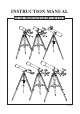
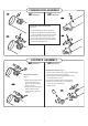
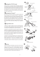
AZ1 & AZ2 MOUNTS Refractor/AZ2 B C G D F E AZ2 A A. Dust Cap / Mask (Remove before Viewing) B. Dew Cap / Sun Shade C. Objective Lens D. Telescope Main Tube E. Finderscope F. Finderscope Bracket G. Alignment Screws H. Focus Locking Screw I. Eyepiece J. Diagonal K. Focus Tube L. Focus Knob H I 5 Reflector/AZ1 4 1 J K 2 3 E L D a F 1. Altitude fine-adjustment control 2. Azimuth Lock 3. Yoke Mount 4. Altitude Lock Knob 5. Yoke Locking Knob G C H B I a. Accessory Tray b. Tripod Leg c.
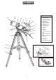
AZ3 MOUNTS B A AZ3 C D E F G H I J 4 K L 3 1 2 A. Dust Cap / Mask (Remove before Viewing) B. Dew Cap / Sun Shade C. Objective Lens D. Piggyback Bracket E. Telescope Main Body F. Finderscope G. Finderscope Bracket H. Alignment Screws I. Focus Tube j. Eyepiece K. Diagonal L. Focus Knob 1. Azimuth Flexible Control Cable 2. Altitude Flexible Control Cable 3. Azimuth Adjustment Knob/ 4. Tube Rings a. Accessory Tray b. Tripod Leg c.
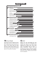
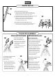
TABLE OF CONTENTS Assembling Your Telescope 5 For AZ1 & AZ2 Tripod Set up Telescope Assembly Finderscope Assembly Eyepiece Assembly 5 5 6 6 For AZ3 Tripod Set up Telescope Assembly Finderscope/Red Dot FinderAssembly Eyepiece Assembly 7 7 8 8 Operating Your Telescope 9 9 9 10 10 10 10 11 11 12 12 12 Aligning the Finderscope Using the Red Dot Finder Operating the AZ1/AZ2 Mount Operating the AZ3 Mount Using the Barlow Lens Focusing Using the Camera Adapter Tube Pointing Your Telescope Calculating the M
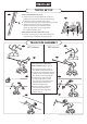
FOR AZ1 & AZ2 TRIPOD SET UP Fig.1 ADJUSTING TRIPOD LEGS (Fig.1) 1) Slowly loosen the height adjustment clamp and gently pull out the lower section of each tripod leg. Tighten the clamps to hold the legs in place. 2) Spread the tripod legs apart to stand the tripod upright. 3) Adjust the height of each tripod leg until the tripod head is properly leveled. Note that the tripod legs may not be at same length when the equatorial mount is level. Fig.2 ATTACHING THE ACCESSORY TRAY (Fig.
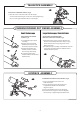
FINDERSCOPE ASSEMBLY AZ2 (refractor) AZ1 (reflector) Fig.7 Fig.7 ATTACHING THE FINDERSCOPE (Fig. 7, 8) 1) Locate finderscope optical assembly. 2) Remove the two knurled thumbscrews near the end of the telescope main tube. 3) Position the finderscope bracket over the screws in the telescope main body. 4) Secure the finderscope bracket with the two knurled thumbscrews. Fig.8 Fig.8 EYEPIECE ASSEMBLY AZ2 (refractor) AZ1 (reflector) INSERTING EYEPIECE (Fig.
FOR AZ3 TRIPOD SET UP Fig.1 ADJUSTING TRIPOD LEGS (Fig.1) 1) Slowly loosen the height adjustment clamp and gently pull out the lower section of each tripod leg. Tighten the clamps to hold the legs in place. 2) Spread the tripod legs apart to stand the tripod upright. 3) Adjust the height of each tripod leg until the tripod head is properly leveled. Note that the tripod legs may not be at same length when the equatorial mount is level. Fig.2 ATTACHING THE ACCESSORY TRAY (Fig.
TELESCOPE ASSEMBLY Fig.5 INSTALLING CONTROL CABLES (Fig.5) 1) Slide the sleeve end of the cable over the nipple on the end of the worm gear. Secure the cable by tightening the set screw against the flat surface on the nipple. FINDERSCOPE/RED DOT FINDER ASSEMBLY Fig.6 Small finderscope Large finderscope / Red dot finder ATTACHING THE FINDERSCOPE (Fig.6) ATTACHING THE FINDERSCOPE BRACKET / RED DOT FINDER (Fig.6) 1) Locate finderscope optical assembly.
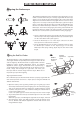
OPERATING YOUR TELESCOPE Aligning the finderscope Fig.b Fig.a Fig.c Fig.d These fixed magnification scopes mounted on the optical tube are very useful accessories. When they are correctly aligned with the telescope, objects can be quickly located and brought to the centre of the field. Alignment is best done outdoors in day light when it's easier to locate objects. If it is necessary to refocus your finderscope, sight on an object that is at least 500 yards (metres) away.
Fig.g Operating the AZ1/AZ2 mount Altitude adjustment This telescope has an altitude(up-down)-azimuth(left-right) mount to control telescope movements. Loosen the azimuth lock knob to make left-right direction movements then tighten to lock. Loosen the altitude lock knob to make course up-down changes. Altitude fine adjustments can be made by rotating the knurled wheel on the altitude fine adjustment rod after tightening the altitude lock knob. (AZ1: Fig.g, AZ2: Fig.
Using the Camera Adapter Tube When you connect a camera directly to your telescope for "prime focus" photography, you sometimes require an adapter so that the camera can be focussed. Some reflectors need more length than the focuser can travel, in order to focus the camera, and some refractors are designed to be used with diagonals, so when used with only a camera, their focal length has to be extended. This is particularly true when photographing near objects.
Calculating the magnification (Power) The magnification produced by a telescope is determined by the focal length of the eyepiece that is used with it. To determine a magnification for your telescope, divide its focal length by the focal length of the eyepieces you are going to use. For example, a 10mm focal length eyepiece will give 80X magnification with an 800mm focal length telescope.
Sky conditions OBSERVING THE SKY Sky conditions are usually defined by two atmospheric characteristics, seeing, or the steadiness of the air, and transparency, light scattering due to the amount of water vapour and particulate material in the air. When you observe the Moon and the planets, and they appear as though water is running over them, you probably have bad "seeing" because you are observing through turbulent air.
PROPER CARE FOR YOUR TELESCOPE Collimating a Newtonian Collimation is the process of aligning the mirrors of your telescope so that they work in concert with each other to deliver properly focused light to your eyepiece. By observing out-of-focus star images, you can test whether your telescope's optics are aligned. Place a star in the centre of the field of view and move the focuser so that the image is slightly out of focus.
Aligning the Primary Mirror Find the three locking screws at the back of your telescope and loosen them by a few turns. Adjusting screw Locking screw Locking screw Adjusting screw If you see 3 large nuts protruding from the back of your telescope and 3 small Phillip's-head screws besides them, the Phillip's-head screws are the locking screws and the large nuts are the adjusting screws.
CAUTION! NEVER USE YOUR TELESCOPE TO LOOK DIRECTLY AT THE SUN. PERMANENT EYE DAMAGE WILL RESULT. USE A PROPER SOLAR FILTER FIRMLY MOUNTED ON THE FRONT OF THE TELESCOPE FOR VIEWING THE SUN. WHEN OBSERVING THE SUN, PLACE A DUST CAP OVER YOUR FINDERSCOPE OR REMOVE IT TO PROTECT YOU FROM ACCIDENTAL EXPOSURE. NEVER USE AN EYEPIECE-TYPE SOLAR FILTER AND NEVER USE YOUR TELESCOPE TO PROJECT SUNLIGHT ONTO ANOTHER SURFACE, THE INTERNAL HEAT BUILD-UP WILL DAMAGE THE TELESCOPE OPTICAL ELEMENTS.