AZ TRACKING TELESCOPES ER ENT P SETU ESC ITY UTIL 3 RATE R TOU 2 IC 1 6 NGC M 5 4 USER 9 CT OBJE ET PLAN 8 7 ID 0 Instruction manual for AZ GoTo telescopes on reverse flip side TR250808V1
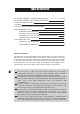
TABLE OF CONTENTS TELESCOPE ASSEMBLY - AUTOTRACKING MOUNTS 3 TELESCOPE ASSEMBLY - MULTIFUNCTION MOUNTS 4 USING THE RED DOT FINDER 5 FOCUSING 5 CALCULATING THE MAGNIFICATION (POWER) 5 FOR ASTRONOMICAL USE 6 POWERING THE TELESCOPE 6 SETTING UP THE TELESCOPE 6 SETTING THE LOCAL LATITUDE FOR ACCURATE TRACKING 7 HAND CONTROL OPERATION 7 FOR TERRESTRIAL USE 8 SETTING UP THE TELESCOPE 8 HAND CONTROL OPERATION 8 BEFORE YOU BEGIN This instruction manual is applicable to all the models list
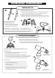
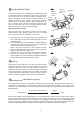
TELESCOPE ASSEMBLY - AUTOTRACKING MOUNTS TRIPOD SET UP Fig.1 ADJUSTING TRIPOD LEGS (Fig.1) 1) Slowly loosen the height adjustment clamp and gently pull out the lower section of each tripod leg. Tighten the clamps to hold the legs in place. 2) Spread the tripod legs apart to stand the tripod upright. 3) Adjust the height of each tripod leg until the tripod head is properly leveled. Note that the tripod legs may not be at same length when the mount is level. Fig.
TELESCOPE ASSEMBLY - MULTIFUNCTION MOUNTS TRIPOD & MOUNT SET UP Fig.6 Fig.7 TRIPOD SET UP 1. Remove the tripod from the box and spread the legs apart until fully extended. 2. Adjust the desired height of the tripod before attaching the fork arm and your optical tube. Minor adjustments can be made later. Loosen the locking mechanisms on each leg and slide the legs to the desired height and then retighten them. MOUNT SET UP 1. Next you will attach your Multi-function mount to the tripod.
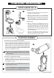
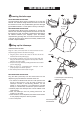
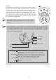
U sing the Red Dot Finder Fig.a The Red Dot Finder is a zero magnification pointing tool that uses a coated glass window to superimpose the image of a small red dot onto the night sky. The Red Dot Finder is equipped with a variable brightness control, azimuth adjustment control, and altitude adjustment control (Fig.a). The Red Dot Finder is powered by a 3-volt lithium battery located underneath at the front.
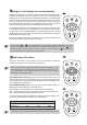
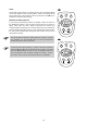
FOR ASTRONOMICAL USE P Fig.d owering the telescope Fig.e SET LAT TRAC SLOW 2 GUIDE 1 FAST 3 6 5 4 7 GO SET CRUISE AUTOTRACKING TELESCOPES The Auto-tracking Mount power requirement is 12-Volts DC Nominal. The maximum voltage should not exceed 16-volts and the minimum is 8-volts. The provided battery pack can hold eight (8) AA alkaline batteries. It can be place in the tray on the tripod. MULTIFUNCTION TELESCOPES The Multi-Function Mount power requirement is 12-Volts DC Nominal.
Setting the local latitude for accurate tracking Setting the local latitude is not required to track an astronomical object but it greatly enhances the tracking accuracy. It requires that you know the latitude of the observing site. To set the latitude for the Northern Hemisphere, use the directional buttons to adjust the telescope tube until the latitude scale reads 0. Turn off the power and turn it back on again.
To activate the TRACKING FUNCTION, you must first find the astronomical object you are seeking. The preferred method of finding objects is called "star-hopping" and there is much written on this method. Remember, you must used the Hand Control unit to move the telescope as you cannot move it manually. When you are ready to track (when the object is in the center of the field of view), press the "Guide" and "Slow" buttons in combination and tracking will be activated (Fig.l).
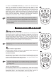
CRUISE Fig.o The CRUISE mode is usable if you want the mount to stop for several seconds at each stored position during slewing. To activate the CRUISE function, press "SET" and "GO" keys in combination (Fig.o). The mount will cruise sequentially among the stored positions. The mount will stay in each position for 5 seconds and then move on to the next position. After one cycle, the mount will stop at the last position for 3 minutes and the cruising cycle will start over again.
SCAN Fig.p The SCAN function allows for scaning among all the stored positions one by one without a stop at each position. There is not waiting at the end of each scan cycle. Hold the "GO" key and press the key to activate the "SCAN" function (Fig.p). SLOW 2 GUIDE 1 ERASE A STORED POSITION 5 GO SET CRUISE Fig.q SET LAT SLOW 2 GUIDE 1 FAST 3 6 5 4 GO SET CRUISE 10 3 4 TRAC To stop the mount during "GOTO", "Cruise", and "Scan" functions, press the and keys simultaneously (Fig.q).