
Use and Care Guide


-8-
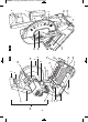
1. Top Carry Handle – This handle is built into
the head assembly for transportation.
2. Switch Lock-OFF Toggle – The toggle
needs to be moved left or right before the
power switch can be pressed.
3. Power Switch – The power switch used with
the Lock-OFF Toggle energizes the unit.
4. Switch Handle – The power switch used
with the ambidextrous toggle energizes the
saw.
5. Lower Blade Guard – The lower blade
guard helps protect your hands from the spin-
ning blade. It retracts as the blade is lowered.
6. Blade – Use only 12” (305 mm) blades with
1” (25.4 mm) arbor hole.
7. Blade Wrench/Storage – Used in blade
change process; tightening and loosening
blade and blade guard.
8. Chip Deflector – This protects against large
chips from entering the upper guard.
9. Upper Blade Guard – Covers upper portion
of the blade.
10. Sliding Base Extension – Provides work-
ing surface to support workpiece, expands to
support longer materials.
11. Base Extension Clamping Lever – Locks
the base extension at the desired positions.
12. Tool Mounting Pads – The two corners of
the saw provide areas to clamp, bolt or
nail/screw the saw to a flat work surface.
13. Chip collection tray– Captures chips. Can
be removed for emptying.
14. Lower Guard Actuation Link –Allows for
smooth movement of the lower guard.
15. Workpiece Clamp – Used to secure the
workpiece against the fence.
16. Miter Lock Lever – Locks and unlocks the
adjustable fence assembly at a desired miter
angle.
17. Miter Scale and Pointer – Allows user to
easily read miter angles. Pointer indicates cur-
rent angle.
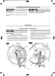
18. Arbor Lock – Press arbor lock button to
keep blade from rotating when loosening or
tightening arbor bolt during blade removal or in-
stallation.
19. Head Assembly Lock Pin – Used to lock
the head assembly in lower position for trans-
porting.
20. Clear Shield – Provides extra protection
from chips.
21. Fence – Secures the workpiece at a de-
sired miter angle.
22. Base – Provides working surface.
23. Quick Release Lever – Releases the
clamp.
24. Cover Plate – Covers blade bolt and
washer.
25. Cover Plate Screw – See chapter “Re-
moving and Installing blades”
26. Cast-in carry handles – Handles for lifting
and carrying the saw located in the front and
rear of the base.
27. Pivot Spring – Keeps head assembly in
UP position.
28. Power Cord
29. Head Assembly
Getting To Know Your Saw
To avoid injury from accidental starting, remove
plug from power source outlet before making
any adjustments.
Model Number.....................SPT62MTC
Blade Ø................................12" (305 mm)
Voltage .................................120 V~ 60 Hz 15 A
No-load speed (n
0
) .............1500 /min
1609B00427 eng.qxp_SPT62MTC 5/12/15 1:53 PM Page 8