Cat. No. 877-92 Operating Instructions SKC Inc. 863 Valley View Road Eighty Four, PA 15330 USA Tel: 724-941-9701 e-mail: skctech@skcinc.
Table of Contents Introduction .................................................................................... 1 DataTrac Setup ............................................................................. 2 SKC DataTrac Pump Manager ..................................................... 7 SKC Real Time Monitor ................................................................. 8 STEL/Timed Run ..........................................................................15 SKC Pump Scheduler.................
2
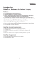
Introduction Introduction DataTrac Software for Leland Legacy Features • Program a sampling operation from a PC • Calibrate pump flow to a primary standard • Display the operating state including flow rate, temperature, atmospheric pressure, run time, and battery status of the connected pump • Create and save a sampling program without a pump connected to the PC • Program up to 26 sampling sequences, each at different flow rates, if desired • Download pump run time data and history to your PC • Document sam
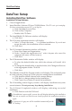
DataTrac Setup DataTrac Setup Installing DataTrac Software Installation of New Software 1. Close all applications. 2. Insert DataTrac Software CD into CD-ROM drive. The CD is set up to autoplay. If it does not autoplay on your PC, go to Step 2a. a. Click Start button on tool bar. b. Click on My Computer. c. Double-click CD Drive. 3. The InstallShield (IS) Welcome window will display. a. Click Next. 4. The IS License Agreement window will display. a. Select “I accept the terms . . .
DataTrac Setup If changes to settings are desired after installation, perform Steps 1 through 4 below. The IS Program Maintenance window will display. Select Modify to change settings. Installation of Software Update (previous version exists on PC) 1. Close all applications. 2. Insert DataTrac Software CD into CD-ROM drive. The CD is set up to autoplay. If it does not autoplay on your PC, go to Step 2a. a. Click Start button on tool bar. b. Click on My Computer. c. Double-click CD Drive. 3.
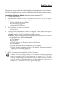
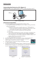
DataTrac Setup Connecting the Pump to a PC (Figure 1) USB port on PC: Use the supplied adapter cable to connect the pump to the PC. Pump interface port W FLO L / mins Adapter cable Figure 1. Hardware Setup First Time Connection 1. 2. 3. 4. 5. Connect the pump to a PC using the DataTrac adapter cable. a. If a Found New Hardware Wizard window displays during connection, follow this procedure: i. Ensure the wizard wants to install software for “USB Serial Port.” 1.
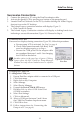
DataTrac Setup Successive Connections 1. 2. 3. 4. 5. Connect the pump to a PC using the DataTrac adapter cable. Activate the pump LCD by pressing any button on the pump keypad. Launch DataTrac Software on the PC by double-clicking the Leland Legacy shortcut icon on the PC desktop. The Leland Legacy connection window will display (Figure 2). a. Click Connect to Pump. The Leland Legacy Connection window will display a shaking hands icon indicating a successful connection (Figure 2A). Proceed to Step 6.
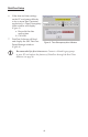
DataTrac Setup 6. 7. If the date and time settings on the PC and pump differ by a day or more than 5 minutes, respectively, a Time Discrepancy Alert window will display (Figure 3). a. Reconcile the date and/or time. b. Click OK. DataTrac Software will load and display the SKC DataTrac Pump Manager window (Figure 4). FLOW L / mins LelandLegacy Figure 3.
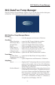
SKC DataTrac Pump Manager SKC DataTrac Pump Manager The SKC DataTrac Pump Manager window (Figure 4) is the first window that opens in DataTrac. All windows are accessible from this main window. Figure 4. SKC DataTrac Pump Manager Window SKC DataTrac Pump Manager Menus File Menu Exit...............................exits the program and returns to Windows View Menu Pump Scheduler ........opens the SKC Pump Scheduler window STEL/Timed Run .......opens the STEL/Timed Run window Sample Sheet ..............
SKC Real Time Monitor SKC Real Time Monitor The SKC Real Time Monitor window (Figure 5) directly controls the pump, allows calibration of flow rate, displays a real time readout of pump operations, and displays the connected pump‘s serial number. I B C D A F E H G Figure 5. Real Time Monitor Window A. B. C. D. E. F. G. H. I.
SKC Real Time Monitor Pump Real Time Monitor Display The Real Time Monitor display (Figure 6) shows the operating status of the connected pump. Pump Status Cell Readout Operating State of the Pump Run ............................pump in run mode Hold ..........................pump in hold mode Fault (Run) ...............pump in flow fault status while running Fault (Hold)..............pump in flow fault status and hold mode Prog (Hold) ..............pump in hold mode while running a program Prog (Run) ....
SKC Real Time Monitor Battery Selection Buttons The Battery Selection Buttons (Figure 7) allow the user to select the battery that is installed in the sample pump. Check the label on the battery pack, and then click the button next to the appropriate battery Part No. Selecting the proper battery ensures that the pump indicates accurate battery status. Figure 7.
SKC Real Time Monitor Set the pump to 10 L/min. If the calibrator displays 9.7 L/min, click the button in Flow Calibrate until the calibrator displays 10 L/min. If the calibrator displays 10.5 L/min, click the button in Flow Calibrate until the calibrator displays 10 L/min. Repeat calibration after sampling to verify flow. Comm Checking Buttons The Comm Checking buttons (Figure 9) turn the communication checking function on or off.
SKC Real Time Monitor Temperature Display The Temperature Display (Figure 11) shows the temperature of the air entering the connected pump. Cell Readout Min ........................................................minimum air temperature during the program run Max........................................................maximum air temperature during the program run TWA ......................................................time-weighted average (TWA) of all air temperatures Ambient ...........................
SKC Real Time Monitor Pressure Display The Pressure Display (Figure 12) shows the atmospheric pressure of the air entering the connected pump. Cell Readout Min ........................................................minimum atmospheric pressure during the program run Max........................................................maximum atmospheric pressure during the program run TWA ......................................................time-weighted average of all atmospheric pressure Ambient ................
SKC Real Time Monitor Units Selection Buttons The Units Selection buttons (Figure 14) allow the user to select the temperature and pressure units of the connected pump. Control Function Fahrenheit ....................................selects the Fahrenheit temperature scale Celsius ..........................................selects the Celsius temperature scale in-Hg .............................................selects the atmospheric pressure display in units of inches of mercury millibar...................
STEL/Timed Run STEL/Timed Run The STEL/Timed Run window (Figure 16) allows the user to set a pump run for a predetermined length of time, e.g., 15 minutes. Once the STEL/Timed Run is set, the user presses the keys on the pump simultaneously to start the run. After the timed run is completed, the pump will stop automatically. Figure 16. STEL/Timed Run Window STEL/Timed Run Menus File Menu Exit.............................exits the STEL/Timed Run window Tools Menu Clear STEL in Pump .................
SKC Pump Scheduler SKC Pump Scheduler The SKC Pump Scheduler window (Figure 17) is the DataTrac programming window. Programs can be created, sent to a pump, saved to a PC, loaded from a disc or a pump, and printed. B G H A F C I D E Figure 17. Pump Scheduler Window A. B. C. D. E. F. G. H. I.
SKC Pump Scheduler Pump Scheduler Menus File Menu Open ..............................opens a pump program previously stored on disc Save ...............................saves a pump program to a PC Print ...............................prints the pump program schedule displayed on the screen Exit.................................exits the Pump Scheduler window View Menu Cycle Scheduler ...........opens Cycle Scheduler window Preview Repeat Schedule ....................
SKC Pump Scheduler Pump Schedule The Pump Schedule (Figure 19) contains pump programs (or pump schedules) set by the Program Edit Bar. The pump is programmed for a sampling operation by sending this list of programs to the pump‘s memory. The Pump Schedule is built by using the Programming buttons described in the next section. The maximum number of programs that can be contained in the Pump Schedule is 26. Figure 19.
SKC Pump Scheduler Insert Button To insert the completed program from the Program Edit Bar into the Pump Schedule (Figure 19), click on the Insert button (Figure 20). The Pump Schedule can hold 26 programs. However, if a large number of programs are to be stored, consider using the Cycle Scheduler (see page 25) or the Repeat Scheduler (see page 26). Cut Button To clear the selected (highlighted) program from the Pump Schedule and place it into the Program Edit Bar, click on the Cut button (Figure 20).
SKC Pump Scheduler FromPump Button To display a Pump Schedule from a previously programmed pump, click on the FromPump button (Figure 20). Time Bump Buttons To increase or decrease all program start and stop times in the Pump Schedule, click on the Time Bump buttons (Figure 32). Save a Program (File Menu) To save information from the Pump Schedule to a PC as a program file, select the Save command from the File menu. The default extension “.pgm” is used to indicate Pump Schedule files.
SKC Pump Scheduler Calendar The Calendar (Figure 26) shows the time interval over which the pump can be programmed. Use the Calendar to select the start and stop dates for the scheduled sample run. Selecting a Date To select a date, click on it then click on the Start Date/Time or Stop Date/Time cell in the Program Edit Bar to enter the date into that cell. Use the right and left arrows to select a different month. Figure 26.
SKC Pump Scheduler Selecting a Time Using the Digital Time Display The Digital Time display (Figure 30) can also be used to select the time, especially outside the clock resolution settings. Doubleclick on the time display to highlight it (Figure 31), then key in the desired time (including the colon). One or more numbers can be individually selected by clicking and dragging across the digit to be changed. Click on the appropriate time cell in the Program Edit Bar to enter the time into that cell.
SKC Pump Scheduler Date/Time Display FLOW To access the Date/Time Display window (Figure 33), go to the Tools menu and select Compare Pump Clock/PC Clock. This feature allows the time and date of the PC and the connected pump to be synchronized. L / mins LelandLegacy Figure 33. Date/Time Display Window Resetting the pump time will issue a Clear History Message (Figure 34). The pump history must be cleared before the pump time can be reset. Figure 34.
SKC Pump Scheduler Scheduler Options To access the Scheduler Options window (Figure 35) in the SKC Pump Scheduler, go to the View menu and select Scheduler Presets. The Scheduler Options window includes User Lock Out, Clear History, and Reset Volume, Time, Temperatures, and Pressures. The Scheduler Options take effect when the Pump Schedule is sent to the pump’s memory from the SKC Pump Scheduler window (see page 16). Figure 35. Scheduler Options Button Function User Lock Out .....................
SKC Pump Scheduler Cycle Scheduler To access the Cycle Scheduler window (Figure 36) in the Pump Scheduler, go to the View menu and select Cycle Scheduler. The Cycle Scheduler window allows the user to program intermittent (repeated start/stop) sampling cycles that will run over several days in a minimal number of steps. See pages 27-30 for an example schedule. Figure 36. Cycle Scheduler Cell/Button Readout/Function Cycle Setup Run Cell ........enter time that each cycle is to run Cycle Setup Hold Cell ..
SKC Pump Scheduler Repeat Scheduler To activate the Repeat Scheduler (Figure 37), go to the Repeat Schedule cell in the Pump Scheduler window and click in the box until a check mark appears. Click on the desired time frame (daily or weekly) and enter the desired number of cycles in the Execute Count cell. Enter the desired flow rate in the Set Flow cell or click the Set Flow button. Click the ToPump button. Go to the View menu and select Preview Repeat Scheduler.
Example Scheduler Program Example Scheduler Program This example program demonstrates step-by-step how to use the SKC Pump Scheduler window (see page 16) to set a program. A sampling operation requires the Leland Legacy to sample at a constant flow of 10 L/min from 8:00 AM to 4:00 PM daily for one work week. Enter the parameters as follows. To Reset Volume, Time, Temperature, and Pump History To set the flow rate: Click on the Set Flow button. The Scheduler Set Flow window opens. Click on the 10.
Example Scheduler Program To insert the program into the Pump Scheduler: Click on the Insert button. The program appears in the Pump Schedule. Note that the program is still displayed in the Program Edit Bar. The Pump Scheduler now has a program that tells the pump to run at a constant flow of 10 L/min from 8:00 AM to 4:00 PM on Monday. The same operating parameters must be entered for each day of the week. To add extra days to the program schedule: Click on the +Day button.
Example Scheduler Program Repeat Scheduler If the user wishes to repeat the example schedule for the next 10 weeks, the Repeat Scheduler could be used to save entry time (refer to Figure 37). 1. In the Pump Scheduler, set up a regular program (see pages 16-24). 2. At the bottom of the window, click on the Repeat Schedule box (a check mark should appear). 3. Click on the Weekly button. 4. Click in the Execute Count box and enter the number 10. 5.
Example Scheduler Program To set the desired Scheduler Options: Select Scheduler Presets from the View menu and click on the desired Scheduler Options (see page 24). To write the program to the Pump: Click on the ToPump button. DataTrac will now write all steps contained in the Pump Schedule to the pump. To save a pump program to a PC: Select the Save command from the File menu. The program displayed in the Pump Schedule will be saved as a program file (.pgm).
SKC Pump History SKC Pump History The SKC Pump History window (Figure 38) displays a record of all operations the pump has performed. Approximately 300 histories can be stored in the pump‘s memory. This window can also be saved to a PC or printed. Figure 38. SKC Pump History Window SKC Pump History Menus File Menu Print History ................prints the current history Save History .................saves a history file to a PC.
SKC Pump History Clear Pump History To clear the pump history, select Clear History from the Tools menu. Change Options* To change display and sample interval pump history options, select Options from the Tools menu. * Changes to these parameters will also be reflected on the pump LCD. Reload History To reload existing pump history, select Reload History from the Tools menu. Print Pump History To print the pump history file displayed on screen, select Print from the File menu (see page 31).
SKC Pump History User Setup ............pump user interface accessed and user adjusting pump Pre-Cal Flow ........single-point calibration mode; first calibration average, date, and time Post-Cal Flow .......single-point calibration mode; final calibration average, date, and time Timed Run............pump running a preset sampling time (ST) Low Bat .................battery depleted FullCal...................full (multiple-point) calibration mode Flow Adjust ..........
Archive History Archive History The Archive History window loads and displays a pump history file that was saved to a PC. This window is empty until a history file is opened. Archive History Menus File Menu Open ..............................opens a saved history file Print ...............................prints the displayed history file Exit.................................returns to the previous window Open a History To open a history file, select Open from the File menu.
Reports Reports DataTrac allows reports or worker exposure profiles to be printed or saved as text and imported into word processing software or a text editor. These files combine the setup data (information denoting sampling media, methods, location, etc.) from the Sample Sheet Setup window (Figure 39) and a pump history (Figure 38). File menu Open ......................opens a saved report file Save as Text ..........saves report as text (.txt) that any word processor or text editor can read Print ......
Reports Load Template .....loads a template file Save Template ......saves a template file Print .......................prints the current sample sheet data displayed on screen Exit.........................exits the Sample Sheet Setup window and returns to the previous window Option Menu Merge Pump ........writes the pump history from the connected pump memory to the displayed sample sheet setup and creates a worker exposure profile Merge File.............
Reports Save Template To save only the information contained in data cells with active check boxes, select Save Template from the File menu. The Save Template command saves the checked data as a template file (.tpl). Print To print the displayed sample setup or template, select Print from the File menu. Worker Exposure Profile A worker exposure profile contains a sample sheet setup file and a pump history. A worker exposure profile can be created using the connected pump’s history or a history file (.
Reports CalChek Full Calibration Data Display and Verification Figure 41. Calibration Info Window Viewing CalChek Full Calibration Data Caution: Full calibration completely clears DataTrac, run time parameters, and the Pump Schedule. Full calibration data can be viewed and printed by going to the DataTrac Pump Manager window and clicking on the View menu. Choose Calibration Info (Figure 41). This window will display calibration results, pump serial number, and date of the last full calibration.
Reports Validating CalChek Full Calibration Data To confirm printed calibration data, open the DataTrac Pump Manager window and click on the View menu. Choose Calibration Info (Figure 41). Click the Print Report button. Go to the Tools menu and choose Confirm Validation Code (Figure 42). Enter the calibration date shown on the printed report, enter each actual flow, and then enter the validation code. Click on the Check Validation Code button.
Index Example Program ......................... 27-30 Fahrenheit Button .............................. 14 Fault Options ..................................... 14 Features .............................................. 1 Flow Calibrate.................................... 10 Flow, Changing Default ..................... 15 Flow Fault .......................................... 14 Files History ”.hst” ................................... 32 Program “.pgm” .............................. 20 Report “.rpt” ...........
Printing Programs ........................................ 20 Reports ........................................... 37 Sample Sheet Setup....................... 36 Pressure Units Button........................ 14 PROG Icon ........................................ 19 Program Edit Bar ............................... 17 Programs ...................................... 17-30 Edit ................................................. 19 Example..................................... 27-30 Files ..........................