
Instruction Manual


7
Calibration
Calibrate pump fl ow rate using a primary standard calibrator, IOM Calibration
Adapter accessory, and a representative loaded IOM Sampler in line.
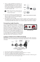
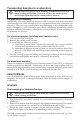
Calibration Adapter Setup (Figure 10)
1. Push an IOM Sampler loaded with a
representative fi lter and casse e through
the hinged bracket and place inlet against
the adapter’s foam ring.
2. Clamp IOM in place with plastic clamping
screw until foam ring compresses by 1 mm.
Ensure IOM inlet is centered.
3. Screw supplied hose barb into threaded hole
in calibration adapter inlet.
4. Use a length of fl exible tubing to connect
hose barb to calibrator outlet.
5. Remove sampler dust cap from outlet.
6. Connect IOM outlet to the inlet of a sample
pump.
Calibrating Pump Flow Rate
Calibrate pump fl ow rate using the IOM Calibration Adapter accessory and an IOM
sampler loaded with a representative fi lter and casse e in line.
1. Insert IOM with loaded fi lter casse e into the calibration adapter (see Calibration
Adapter Setup and Figure 10).
2. Calibrate pump fl ow rate to 2 L/min. See calibrator and sample pump operating
instructions for additional information.
3. Disconnect IOM from pump and calibrator and remove representative casse e.
Set aside for fl ow rate verifi cation a er sampling.
Sampling
Wear powder-free gloves when handling casse es. Users may wish to
use sterile gloves depending on the contaminant of interest.
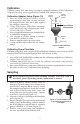
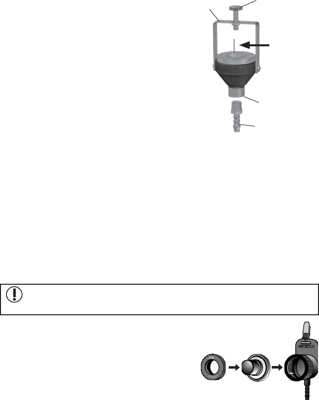
1. Remove a newly loaded casse e from its
transport clip and remove the casse e cover.
Ensure the O-rings are fi ed correctly inside
the sampler housing body. Insert the casse e
into a clean IOM housing body. Screw the
front plate into the housing body. Tighten
to achieve a good seal (Figure 11).
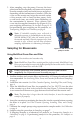
2. Clip onto a worker’s clothing in the breathing
zone (Figure 12).
3. Ensure sampler dust cap is removed from the
outlet. Using fl exible tubing, connect outlet of
the IOM Sampler with the inlet of a sample
pump calibrated to 2 L/min (Figure 12).
4. Remove cover, start pump, and sample for
the time specifi ed in the method used.
Figure 11. Insert loaded cassette
in sampler body and screw on
front plate.
Figure 10. IOM Calibration
Adapter
Foam ring
Plastic
clamping
screw
Hinged
bracket
Adapter
inlet
Hose barb
Insert IOM here,
inlet side down