
User Manual

18
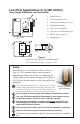
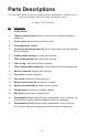
Parts Descriptions
Use only SKC-approved parts to ensure reliable performance. Failure to do so
voids any warranty and UL Listing for intrinsic safety.
.
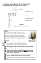
See page 19 for drawing.
No. Description
1 On/Off switch
2 Tamper-resistant cover protects controls from accidental contact or
tampering.
3 Cover screw fastens tamper-resistant cover.
4 Flow adjustment control
5 Accessory mounting screws (2) secure accessories such as impinger
and trap holders.
6 Intake (pump housing), air intake port and trap
7 Filter housing screws (4) secure fi lter housing.
8 Filter O-ring - leak seal for fi lter in housing
9 Filter (crimped fi ber polyester) prevents particles from entering pump.
10 Built-in rotameter monitors fl ow changes.
11 Cap screw accesses regulator.
12 Cap screw accesses air discharge port.
13 Battery pack screws (2) secure pack to pump.
14 Battery pack assembly provides power to pump.
15 Charging jack, connector for battery charger
16 Belt clip secures pump to worker’s belt.
A Compensation Pot A adjusts pump compensation, which is factory set.
Access screw guards against accidental contact or tampering.
B Compensation Pot B adjusts pump compensation, which is factory
set. Access screw guards against accidental contact or tampering.