Operating Instructions Universal Sample Pump Cat. No. 224-44XR SKC Inc.
Table of Contents Description ........................................................................................... 1 Performance Profile ...................................................................... 2 Operation.............................................................................................. 5 High Flow Applications ................................................................. 5 Low Flow Single-tube Applications ...............................................
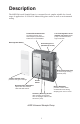
Description The 44XR Universal Sample Pump is a constant flow air sampler suitable for a broad range of applications. It is ideal for industrial hygiene studies as well as environmental testing. Durable RFI-shielded Case provides protection from radio frequency interference between 27 and 1000 MHz. Rechargeable Battery Low Flow Regulator Screw (beneath cap screw) allows pump to be switched from high to low flow.
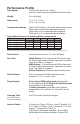
Performance Profile Flow Range: 1000 to 5000 ml/min (UL Listed) (5 to 500 ml/min requires adjustable low flow holder) Weight: 34 oz (964 gm) Dimensions: 5.1 x 4.7 x 1.9 in (13 x 11.9 x 4.
Operating Temperature: 32 to 113 F (0 to 45 C) Storage Temperature: -4 to 113 F (-20 to 45 C) Charging Temperature: 50 to 113 F (10 to 45 C) Operating Humidity: 0 to 95% non-condensing Protect sample pump from weather when in use outdoors. Multiple-tube Sampling: Built-in constant pressure regulator allows user to take up to four simultaneous tube samples at different flow rates up to 500 ml/min each using optional adjustable low flow holder.
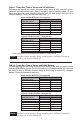
Table 1. Pump Run Time in Hours with NiCad Battery Following are typical run times achieved when using a fully charged nickelcadmium (NiCad) battery pack. Data is sorted by type of sample media. All run times are listed in hours. Results obtained using a new pump and new fully charged battery. Pump performance may vary. Mixed Cellulose (MCE) filter, 0.8-μm pore size Filter Diameter Flow Rate (L/min) 37 mm 25 mm 2.0 24.1 16.3 2.5 21.4 14.5 3.0 19.1 11.0 3.5 17.8 10.7 4.0 15.4 ** 4.5 14.
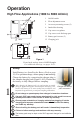
Operation High Flow Applications (1000 to 5000 ml/min) 5 6 AIRCHEK SAMPLER U¨ L LISTED 124U 5 4 3 AIRCHEK SAMPLER MODEL 224-44XR 2 On/Off switch 4 Flow adjustment screw 5 Accessory mounting screws (2) 6 Intake filter housing 11 Cap screw to regulator 1 1 1 12 Cap screw to air discharge port ON FLOW ADJ 13 Battery pack screws (2) 4 15 Charging jack FRONT 13 11 TOP 12 15 13 BACK Figure 1 Front, back, and top views of 44XR Sampler For additional drawings, see pages 19-21.
Deactivating the Regulator 2 To ensure the pump is set for high flow, remove the cap screw (Figure 1, #11) covering the regulator valve and turn the exposed screw clockwise until it stops. (Do not overtighten.) Replace the cap screw. The pump is now set for high flow. For high flow, turn valve screw clockwise. Setting or Verifying Flow Rate Ensure pump has run for five minutes before proceeding with calibration.
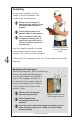
Sampling For personal sampling, clip the sample collection medium to the worker in the breathing zone. Before use, allow pump to equilibrate after moving it from one temperature extreme to another. Protect sample pump from weather when in use outdoors. Use of any device other than the approved battery pack to power the pump voids the UL Listing for intrinsic safety and any warranty. 4 Clip sampling medium to worker and pump to belt.
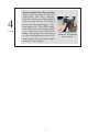
4 cont’d Pressure Applications (Bag Sampling) When using the pump for pressure applications, such as bag sampling, thread the exhaust port fitting supplied with the pump into the air discharge port on top of the pump (Figure 1, #12); hand tighten only. Using PTFE tubing, connect the inlet of the sample medium (e.g., sample bag) to the exhaust port fitting on the pump. Turn on the pump to collect the appropriate volume of air. Shut off pump and close inlet on sample medium to stop sampling.
Low Flow Applications (5 to 500 ml/min) Using Single Adjustable Low Flow Holder 5 6 AIRCHEK SAMPLER U¨ L LISTED 124U 5 4 3 AIRCHEK SAMPLER MODEL 224-44XR 2 On/Off switch 4 Flow adjustment screw 5 Accessory mounting screws (2) 6 Intake filter housing 11 Cap screw to regulator 1 1 1 12 Cap screw to air discharge port ON FLOW ADJ 13 Battery pack screws (2) 4 15 Charging jack FRONT 13 11 TOP 12 15 13 BACK Figure 2 Front, back, and top views of 44XR Sampler For additional drawings, s
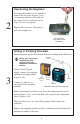
Activating the Regulator 2 Remove the tamper-resistant cover. Start the pump using the on/off switch (Figure 2, #1), and adjust the flow rate using the flow adjustment screw (Figure 2, #4) until the builtin rotameter reads approximately 1.5 L/min. Remove the cap screw covering the regulator valve (Figure 2, #11) and turn the exposed screw four to five turns counterclockwise. For low flow, turn valve screw counterclockwise. Replace the cap screw. The pump is now set for low flow.
3 cont’d Loosen the brass flow adjust screw (Figure 3, #1) on the low flow holder. Activate the pump by using the on/off switch (Figure 2, #1). Adjust the flow rate by turning the flow adjust screw (Figure 3, #1) on the holder until the calibrator indicates the Turn screw to adjust flow. desired flow. Flow adjust screw Do not adjust the flow on the pump. Adjust the flow only by using the flow adjust screw on the low flow holder. Turn off the pump and disconnect the calibrator.
Low Flow Applications (5 to 500 ml/min) Using Multiple-tube Adjustable Low Flow Holder Top view of flow adjust screws 1 Anti-tamper cover 2 Flow adjust screws 3 Rubber sleeve 4 Sorbent sample tube 5 Protective cover Figure 4 Quad Adjustable Low Flow Holder Setup For a diagram of the pump, see Figure 2, page 9. Install battery (see Installing the Battery Pack on page 16). For optimum charge, ensure pump is not running.
Setting or Verifying Flow Rate Note: When performing multiple-tube sampling using an adjustable low flow holder (dual, tri, or quad), ensure the regulator has been activated and the pump flow rate is set at 1.5 L/min. The maximum flow rate through any one tube is 500 ml/min*. Calculate the sum of all tube flow rates. If the sum is ≤ 1000 ml/ min, proceed with calibration and sampling without any further adjustment to pump flow rate.
Do not adjust the flow on the pump. Adjust the flow only by using the flow adjust screw on the low flow holder. Do not exceed 500 ml/min flow rate per tube. 2 cont’d Screw Screw Remove the calibrator from the tube and connect to the exposed end of the next sorbent tube. Repeat the flow adjustment process until all tubes are flow calibrated. Changing the flow on one Figure 5 tube will not affect the flow rate through Cut-away of Tri/Quad Low the remaining tubes.
Maintenance Pump Inlet Filter The 44XR Sampler is fitted with a filter/trap inside a clear plastic intake port housing. This prevents particles from being drawn into the pump mechanism. The filter should be visually checked to assure that it does not become clogged. If maintenance is necessary, follow this procedure: 1. Clean dust and debris from around the filter housing. 2. Remove the four screws and the front filter housing. 3. Remove and discard the filter membrane. 4. Remove O-ring. 5.
Installing the Battery Pack Note: To enhance battery life, SKC ships battery packs separate from the pump. Once installed, completely charge battery pack before operating pump. 1. Loosen the two case screws above and below the belt clip. 2. Slip the front edge of the battery pack under the belt clip and position battery pack to engage the grooves in the case. 3. Slide battery pack toward the pump until it is flush with the pump case on all sides. 4.
Use of a repaired or rebuilt battery pack voids any warranty and the UL Listing for intrinsic safety. Do not charge or operate the pump with charger in hazardous locations! Use only SKC-approved charger and battery pack designed for the Universal Sample Pump to ensure reliable performance. Failure to do so voids any warranty and UL Listing for intrinsic safety. Use of any device other than the approved battery pack to power the pump voids the UL Listing for intrinsic safety and any warranty.
Parts Descriptions Use only SKC-approved parts to ensure reliable performance. Failure to do so voids any warranty and UL Listing for intrinsic safety. . See page 19 for drawing. No. Description 1 On/Off switch 2 Tamper-resistant cover protects controls from accidental contact or tampering. 3 Cover screw fastens tamper-resistant cover. 4 Flow adjustment control 5 Accessory mounting screws (2) secure accessories such as impinger and trap holders.
224-44XR Sample Pump See page 18 for parts listing.
Replacement Parts See drawings on page 21.
See page 20 for replacement parts listing.
Optional Accessories Calibrator Cat. No.
SKC Limited Warranty and Return Policy SKC products are subject to the SKC Limited Warranty and Return Policy, which provides SKC’s sole liability and the buyer’s exclusive remedy. To view the complete SKC Limited Warranty and Return Policy, go to http://www.skcinc. com/warranty.asp.