Wireless Network Broadband Router 54G+ WL-527 Full manual 1
Copyright The contents of this publication may not be reproduced in any part or as a whole, stored, transcribed in an information retrieval system, translated into any language, or transmitted in any form or by any means, mechanical, magnetic, electronic, optical, photocopying, manual, or otherwise, without the prior written permission. Trademarks All products, company, brand names are trademarks or registered trademarks of their respective companies. They are used for identification purpose only.
Table of Contents CHAPTER 1 INTRODUCTION ............................................................................... 6 1.1 FEATURES.................................................................................................... 6 1.2 MINIMUM REQUIREMENTS .......................................................................... 7 1.3 PACKAGE CONTENT ..................................................................................... 7 CHAPTER 2 HARDWARE INSTALLATION .......................
6.2.4 PPTP........................................................................................................................................................... 27 6.2.5 L2TP........................................................................................................................................................... 28 6.2.6 TELSTRA BIG POND ..................................................................................................................................... 28 6.3 DNS ......
10.5 RESET (RESTART) THE ROUTER ................................................................. 56 10.6 DDNS ......................................................................................................... 57 APPENDIX A ............................................................................................... 58 GLOSSARY...................................................................................................
Chapter 1 Introduction Congratulations on purchasing this Wireless Broadband Router. This Wireless Broadband Router is a cost-effective IP Sharing Router that enables multiple users to share the Internet through an ADSL or cable modem. Simply configure your Internet connection settings in the Wireless Broadband Router and plug your PC to the LAN port and you're ready to share files and access the Internet.
1.2 Minimum Requirements • One External xDSL (ADSL) or Cable modem with an Ethernet port (RJ-45) • Network Interface Card (NIC) for each Personal Computer (PC) • PCs with a Web-Browser (Internet Explorer 4.0 or higher, or Netscape Navigator 4.7 or higher) 1.
Chapter 2 Hardware Installation 2.1 Panel Layout 2.1.1 Front LEDs Figure 2-1 Front LEDs LEDs: LED Function Color Status Description POWER Power indication Green On Power is being applied to this product. The corresponding WAN or LAN port is On LNK/ACT Link Status linked. Green Blinking 802.11G Wireless Activity Data Rate sending or receiving data. On Wireless LAN had been enabled Blinking Sending or receiving data via wireless.
2.1.2. Rear Panel Figure 2-2 Rear Panel Ports: Port Description PWR Power inlet WAN the port where you will connect your cable (or DSL) modem or Ethernet router. Port 1-4 the ports where you will connect networked computers and other devices. To reset system settings to factory defaults, press the reset button for at least 4 seconds. Reset To reboot the device, press the reset button less than 4 seconds.
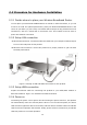
2.2 Procedure for Hardware Installation 2.2.1 Decide where to place your Wireless Broadband Router You can place your Wireless Broadband Router on a desk or other flat surface, or you can mount it on a wall. For optimal performance, place your Wireless Broadband Router in the center of your office (or your home) in a location that is away from any potential source of interference, such as a metal wall or microwave oven. This location must be close to power and network connection. 2.2.
Chapter 3 Network Settings and Software Installation To use this product correctly, you have to properly configure the network settings of your computers and install the attached setup program into your MS Windows platform (Windows 95/98/NT/2000). 3.1 Make The Correct Network Settings for your PC The default IP address of this product is 192.168.0.1, and the default subnet mask is 255.255.255.0. These addresses can be changed on your need, but the default values are used in this manual.
1. Is the Ethernet cable correctly connected between this product and your computer? Tip: The LAN LED of this product and the link LED of network card on your computer must be lighted. 2. Is the TCP/IP environment of your computers properly configured? Tip: If the IP address of this product is 192.168.0.1, the IP address of your computer must be 192.168.0.X and default gateway must be 192.168.0.1.
Chapter 4 Configuring Wireless Broadband Router This product provides Web based configuration scheme, that is, configuring by your Web browser, such as Netscape Communicator or Internet Explorer. This approach can be adopted in any MS Windows, Macintosh or UNIX based platforms.
4.1 Start-up and Log in Activate your browser, and disable the proxy or add the IP address of this product into the exceptions. Then, type this product’s IP address in the Location (for Netscape) or Address (for IE) field and press ENTER. For example: http://192.168.0.1. After the connection is established, you will see the web user interface of this product. There are two appearances of web user interface: for general users and for system administrator.
4.2 Status The Status section allows you to monitor the current status of your router. You can use the Status page to monitor: the connection status of the Broadband router's WAN/LAN interfaces, the current firmware and hardware version numbers, any illegal attempts to access your network, and information on all DHCP client PCs currently connected to your network. Parameters Description 4.2 Status Shows the router’s system information 4.2.
4.2.1 Device Status View the Broadband router’s current configuration settings. The Device Status displays the configuration settings you’ve configured in the Wizard/Basic Settings/Wireless Settings section. Parameters Description Device Status This page displays the Broadband router LAN port’s current LAN IP Address and Subnet Mask. It also shows whether the DHCP Server function is enabled/disabled..
4.2.2 Internet Status View the Broadband router’s current Internet connection status and other related information Parameters Description Internet Connection This page displays whether the WAN port is connected to a Cable/DSL connection. It also displays the router’s WAN port: WAN IP address, Subnet Mask, and ISP Gateway as well as the Primary DNS and Secondary DNS being used.
4.2.3 DHCP Client status View your LAN client's information that is currently linked to the Broadband router's DHCP server. Parameters Description Active DHCP Client This page shows all DHCP clients (LAN PCs) currently connected to your network. The “Active DHCP Client Table” displays the IP address and the MAC address and Time Expired of each LAN Client.
4.2.4 System Log View the operation log of the system. Parameters System Log Description This page shows the current system log of the Broadband router. It displays any event occurred after system start up. At the bottom of the page, the system log can be saved to a local file for further processing or the system log can be cleared or it can be refreshed to get the most updated situation. When the system is powered down, the system log will disappear if not saved to a local file.
4.2.5 Statistics View the statistics of packets sent and received on WAN, LAN and Wireless LAN. Parameters Description Statistics Shows the counters of packets sent and received on WAN, LAN and Wireless LAN.
5. Run Setup Wizard • Click Wizard to configure the router. • The Setup wizard will now be displayed; check that the modem is connected and click Next. • Select your country from the Country list. • From Service, select your internet provider. Click Next.
• Depending on the chosen provider, you may need to enter your user name and password, MAC address or hostname in the following window. After you have entered the correct information, click Next. • Click APPLY to complete the configuration. • The router will now save the settings and restart, please wait 30 seconds and you will transferred back to the status window. The configuration is complete. • Wait for about 10 seconds to allow the router to connect to the Internet.
Chapter 6 Basic Settings 6.1 LAN Settings The LAN Port screen below allows you to specify a private IP address for your router’s LAN ports as well as a subnet mask for your LAN segment. Parameters Default Description IP address 192.168.0.1 This is the router’s LAN port IP address (Your LAN clients default gateway IP address) IP Subnet Mask 255.255.255.0 Specify a Subnet Mask for your LAN segment 802.1d Spanning Tree Disabled If 802.
DHCP lends an IP address to your LAN clients. The DHCP will change your LAN client’s IP address when this time threshold period is reached IP Address Pool You can select a particular IP address range for your DHCP server to issue IP addresses to your LAN Clients. Note: By default the IP range is from: Start IP 192.168.0.100 to End IP 192.168.0.199.
Parameters Description 6.2.1 Dynamic IP address Your ISP will automatically give you an IP address 6.2.2 Static IP address Your ISP has given you an IP address already 6.2.3 PPPoE Your ISP requires PPPoE connection. 6.2.4 PPTP Your ISP requires you to use a Point-to-Point Tunneling Protocol (PPTP) connection. 6.2.5 L2TP Your ISP requires L2TP connection. 6.2.6 Telstra Big Pond Your ISP requires Telstra Big Pond connection.
Parameter Description User Name Enter the User Name provided by your ISP for the PPPoE connection Password Enter the Password provided by your ISP for the PPPoE connection Service Name This is optional. Enter the Service name should your ISP requires it, otherwise leave it blank. MTU This is optional. You can specify the maximum size of your transmission packet to the Internet. Leave it as it is if you to not wish to set a maximum packet size.
6.2.4 PPTP Select PPTP if your ISP requires the PPTP protocol to connect you to the Internet. Your ISP should provide all the information required in this section. Parameter Description Obtain an IP address automatically The ISP requires you to obtain an IP address by DHCP before connecting to the PPTP server. Use following IP address The ISP give you a static IP to be used to connect to the PPTP server. IP Address This is the IP address that your ISP has given you to establish a PPTP connection.
application software, computer virus or hacker attacks from the Internet. For example, some software sends network packets to the Internet in the background, even when you are not using the Internet. So please turn off your computer when you are not using it. This function also may not work with some ISP. So please make sure this function can work properly when you use this function in the first time, especially your ISP charge you by time used. 6.2.
6.3 DNS A Domain Name System (DNS) server is like an index of IP addresses and Web addresses. If you type a Web address into your browser, such as www.router.com, a DNS server will find that name in its index and the matching IP address. Most ISPs provide a DNS server for speed and convenience. If your Service Provider connects you to the Internet with dynamic IP settings, it is likely that the DNS server IP address is provided automatically.
Chapter 7 Wireless Settings 7.1 Wireless Basic Settings You can set parameters that are used for the wireless stations to connect to this router. The parameters include Mode, ESSID, Channel Number and Associated Client. Parameters Description Mode It allows you to set the AP to AP, Station, Bridge or WDS mode. Band It allows you to set the AP fix at 802.11b or 802.11g mode. You also can select B+G mode to allow the AP select 802.11b and 802.11g connection automatically.
Set Security Click the “Set Security” button, then a “WDS Security Settings” will pop up. You can set the security parameters used to bridge access points together here when your AP is in AP Bridge modes. 7.2 Advanced Wireless Settings You can set advanced wireless LAN parameters of this router. The parameters include Authentication Type, Fragment Threshold, RTS Threshold, Beacon Interval, Preamble Type.
Data Rate The “Data Rate” is the rate this access point uses to transmit data packets. The access point will use the highest possible selected transmission rate to transmit the data packets. Preamble Type The “Long Preamble” can provide better wireless LAN compatibility while the “Short Preamble” can provide better wireless LAN performance. Broadcast ESSID If you enable “Broadcast ESSID”, every wireless station located within the coverage of this access point can discover this access point easily.
Parameters Description Key Length You can select the WEP key length for encryption, 64-bit or 128-bit. Larger WEP key length will provide higher level of security, but the throughput will be lower. Key Format You may select to select ASCII Characters (alphanumeric format) or Hexadecimal Digits (in the "A-F", "a-f" and "0-9" range) to be the WEP Key. For example: ASCII Characters: guest Hexadecimal Digits: 12345abcde Default Key Select one of the four keys to encrypt your data.
7.3.2 802.1x only IEEE 802.1x is an authentication protocol. Every user must use a valid account to login to this Access Point before accessing the wireless LAN. The authentication is processed by a RADIUS server. This mode only authenticates users by IEEE 802.1x, but it does not encrypt the data during communication. Parameters Description RADIUS Server IP address The IP address of external RADIUS server. RADIUS Server Port The service port of the external RADIUS server.
7.3.3 WPA Pre-shared key Wi-Fi Protected Access (WPA) is an advanced security standard. You can use a pre-shared key to authenticate wireless stations and encrypt data during communication. It uses TKIP or CCMP(AES) to change the encryption key frequently. So the encryption key is not easy to be broken by hackers. This can improve security very much. Parameters Description WPA(TKIP) TKIP can change the encryption key frequently to enhance the wireless LAN security.
7.3.4 WPA Radius Wi-Fi Protected Access (WPA) is an advanced security standard. You can use an external RADIUS server to authenticate wireless stations and provide the session key to encrypt data during communication. It uses TKIP or CCMP(AES) to change the encryption key frequently. This can improve security very much. Parameters Description WPA(TKIP) TKIP can change the encryption key frequently to enhance the wireless LAN security.
7.4 Access Control This wireless router provides MAC Address Control, which prevents the unauthorized MAC Addresses from accessing your wireless network. Parameters Description Enable wireless access control Enable wireless access control Add MAC address into the list Fill in the "MAC Address" and "Comment" of the wireless station to be added and then click "Add". Then this wireless station will be added into the "Current Access Control List" below.
Chapter 8 Firewall Settings The Broadband router provides extensive firewall protection by restricting connection parameters, thus limiting the risk of hacker attack, and defending against a wide array of common Internet attacks. However, for applications that require unrestricted access to the Internet, you can configure a specific client/server as a Demilitarized Zone (DMZ). Note: To enable the Firewall settings select Enable and click Apply 8.
Public IP Address The IP address of the WAN port or any other Public IP addresses given to you by your ISP Client PC IP Address Input the IP address of a particular host in your LAN that will receive all the packets originally going to the WAN port/Public IP address above Note: You need to give your LAN PC clients a fixed/static IP address for DMZ to work properly. You can now configure other advance sections or start using the router (with the advance settings in place) 8.
Sync Flood Protection the router from Sync Flood attack. Click at the bottom of the screen to save the above configurations. You can now configure other advance sections or start using the router (with the advance settings in place) 8.3 Access Control If you want to restrict users from accessing certain Internet applications/services (e.g. Internet websites, email, FTP etc.), then this is the place to set that configuration.
just click "Delete All" button. Filter client PC by MAC Check “Enable MAC Filtering” to enable MAC Filtering. Add PC Fill in “Client PC MAC Address” and “Comment” of the PC that is allowed to access the Internet, and then click “Add”. If you find any typo before adding it and want to retype again, just click "Reset" and the fields will be cleared. Remove PC If you want to remove some PC from the "MAC Filtering Table", select the PC you want to remove in the table and then click "Delete Selected".
Add URL Keyword Fill in “URL/Keyword” and then click “Add”. You can enter the full URL address or the keyword of the web site you want to block. If you find any typo before adding it and want to retype again, just click "Reset" and the field will be cleared. Remove URL Keyword If you want to remove some URL keyword from the "Current URL Blocking Table", select the URL keyword you want to remove in the table and then click "Delete Selected".
Chapter 9 Advanced Settings Network Address Translation (NAT) allows multiple users at your local site to access the Internet through a single Public IP Address or multiple Public IP Addresses. NAT provides Firewall protection from hacker attacks and has the flexibility to allow you to map Private IP Addresses to Public IP Addresses for key services such as Websites and FTP. Select Disable to disable the NAT function.
forward “TCP” or “UDP” packets only or select “both” to forward both “TCP” and “UDP” packets. Port Range The range of ports to be forward to the private IP. Comment The description of this setting. Add Port Forwarding Fill in the "Private IP", “Type”, “Port Range” and "Comment" of the setting to be added and then click "Add". Then this Port Forwarding setting will be added into the "Current Port Forwarding Table" below.
Parameters Description Enable Virtual Server Enable Virtual Server. Private IP This is the LAN client/host IP address that the Public Port number packet will be sent to. Note: You need to give your LAN PC clients a fixed/static IP address for Virtual Server to work properly.
9.3 Special Applications Some applications require multiple connections, such as Internet games, video conferencing, Internet telephony and others. In this section you can configure the router to support multiple connections for these types of applications. Parameters Description Enable Trigger Port Enable the Special Application function. Trigger Port This is the out going (Outbound) range of port numbers for this particular application.
Popular applications This section lists the more popular applications that require multiple connections. Select an application from the Popular Applications selection. Once you have selected an application, select a location (1-10) in the Copy to selection box and then click the Copy to button. This will automatically list the Public Ports required for this popular application in the location (1-10) you’d specified.
9.4 ALG Settings You can select applications that need “Application Layer Gateway” to support. Parameters Description Enable You can select to enable “Application Layer Gateway”, then the router will let that application correctly pass though the NAT gateway. 9.5 UpnP Settings With UPnP, all PCs in you Intranet will discover this router automatically. So you do not have to do any configuration for your PC and can access the Internet through this router easily.
Parameters UPnP Feature Default Disable Description You can Enable or Disable UPnP feature here. After you enable the UPnP feature, all client systems that support UPnP, like Windows XP, can discover this router automatically and access the Internet through this router without any configuration. The NAT Traversal function provided by UPnP can let applications that support UPnP smoothly connect to Internet sites without any incompatibility problem due to the NAPT port translation. 9.
Parameters Description Enable/Disable QoS You can check “Enable QoS” to enable QoS function for the WAN port. You also can uncheck “Enable QoS” to disable QoS function for the WAN port. Add a QoS rule into the table Click “Add” then you will enter a form of the QoS rule. Click “Apply” after filling out the form and the rule will be added into the table.
150 – the range of 50 port numbers. Remote IP Address Enter the remote IP address range of the packets that this rule will apply to. If you assign 192.168.2.3 – 192.168.2.5, it means 3 IP addresses: 192.168.2.3, 192.168.2.4 and 192.168.2.5 Remote Port Range Enter the remote port range of the packets that this rule will apply to. You can assign a single port number here or assign a range of port numbers by assigning the first port number and the last port number of the range.
Chapter 10 Tools You can change the password required to log into the broadband router's system web-based management. By default, there is no password. So please assign a password to the Administrator as soon as possible, and store it in a safe place. Passwords can contain 0 to 12 alphanumeric characters, and are case sensitive. Parameters Description Current Password Enter your current password for the remote management administrator to login to your Broadband router.
10.1 Timezone The Time Zone allows your router to reference or base its time on the settings configured here, which will affect functions such as Log entries and Firewall settings. Parameter Description Set Time Zone Select the time zone of the country you are currently in. The router will set its time based on your selection. Time Server Address The router default the “Time Server Address” is “192.43.244.18” Enable Daylight Savings The router can also take Daylight savings into account.
10.2 Remote Management The remote management function allows you to designate a host in the Internet the ability to configure the Broadband router from a remote site. Enter the designated host IP Address in the Host IP Address field. Parameters Description Host Address This is the IP address of the host in the Internet that will have management/configuration access to the Broadband router from a remote site.
Port The port number of remote management web interface. Enabled Select “Enabled” to enable the remote management function. Click at the bottom of the screen to save the above configurations. You can now configure other advance sections or start using the router (with the advance settings in place) 10.3 Firmware Upgrade This page allows you to upgrade the router’s firmware. Parameters Description Firmware Upgrade This tool allows you to upgrade the Broadband router’s system firmware.
10.4 Back-up Settings The Backup screen allows you to save (Backup) the router’s current configuration setting. Saving the configuration settings provides an added protection and convenience should problems occur with the router and you have to reset to factory default. When you save the configuration setting (Backup) you can re-load the saved configuration into the router through the Restore selection.
10.6 DDNS DDNS allows you to map the static domain name to a dynamic IP address. You must get an account, password and your static domain name from the DDNS service providers. This router supports DynDNS, TZO and other common DDNS service providers.
Appendix A How to Manually find your PC’s IP and MAC address 1) In Window’s open the Command Prompt program 2) Type Ipconfig /all and • Your PC’s IP address is the one entitled IP address (e.g. 192.168.1.77) • The router’s IP address is the one entitled Default Gateway (e.g. 192.168.1.254) • Your PC’s MAC Address is the one entitled Physical Address (e.g.
Glossary Default Gateway (Router): Every non-router IP device needs to configure a default gateway’s IP address. When the device sends out an IP packet, if the destination is not on the same network, the device has to send the packet to its default gateway, which will then send it out towards the destination. DHCP: Dynamic Host Configuration Protocol. This protocol automatically gives every computer on your home network an IP address.
When both are represented side by side in their binary forms, all bits in the IP address that correspond to 1’s in the network mask become part of the IP network address, and the remaining bits correspond to the host ID. For example, if the IP address for a device is, in its binary form, 11011001.10110000.10010000.00000111, and if its network mask is, 11111111.11111111.11110000.00000000 It means the device’s network address is 11011001.10110000.10010000.00000000, and its host ID is, 00000000.00000000.
FTP TCP 21 SMTP TCP 25 POP3 TCP 110 H.323 TCP 1720 SNMP UCP 161 SNMP Trap UDP 162 HTTP TCP 80 PPTP TCP 1723 PC Anywhere TCP 5631 PC Anywhere UDP 5632 PPPoE: Point-to-Point Protocol over Ethernet. Point-to-Point Protocol is a secure data transmission method originally created for dial-up connections; PPPoE is for Ethernet connections. PPPoE relies on two widely accepted standards, Ethernet and the Point-to-Point Protocol.
on top of the IP (Internet Protocol), a network layer protocol. WAN: Wide Area Network. A network that connects computers located in geographically separate areas (e.g. different buildings, cities, countries). The Internet is a wide area network. Web-based management Graphical User Interface (GUI): Many devices support a graphical user interface that is based on the web browser.