(Wireless) IP Camera LN-402/WL-400 Full Manual
About This Guide This manual describes Internet Camera, including a description of the features, as well as the installation procedures and web configuration. Included in the manual are the operating procedures for the IPView application.
1. Introduction Thank you for the purchase of the Internet Camera connecting directly to an Ethernet or Fast Ethernet. It is different from the conventional PC Camera, the Internet Camera is a standalone system with built-in CPU and web-based solutions providing a low cost solution that can transmit high quality video images for monitoring. The Internet Camera can be managed remotely, accessed and controlled from any PC/Notebook over the Intranet or Internet via a web browser.
Pentium 3 450Mhz or above 64MB video memory 800x600 video resolution at 16-bits or above 3. Features and Benefits This section describes the features and benefits of the Internet Camera Simple To Use The Internet Camera is a standalone system with built-in CPU requiring no special hardware or software such as PC frame grabber cards. The Internet Camera supports both ActiveX mode (for Internet Explorer users) and Java mode (for Internet Explorer and Netscape Navigator users).
users name and password are permitted with privilege setting controlled by the administrator. Remote Utility The powerful IPView application assigns the administrator with a pre-defined user ID and password, allowing the administrator to modify the Internet Camera settings from the remote site via Intranet or Internet. When a new firmware is available, you can also upgrade remotely over the network for added convenience. Users are also allowed to monitor the image, and take snapshots.
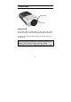
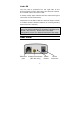
Front Panel Link/Act Power Power LED The Power LED is positioned on the right side of the Internet Camera’s lens while facing the Internet Camera. A steady blue light confirms that the Internet Camera is powered on. Note: There are three settings for the Power LED to control the light illumination for monitoring purpose from Normal / Off / Dummy. Please refer to the Web Configuration section for detailed information and usage.
Link LED The Link LED is positioned on the right side of the Internet Camera’s lens while facing the Internet Camera. It is located right of the Power LED A steady orange light confirms that the camera has good connection to LAN connectivity. Dependent on the data traffic the LED will begin to flash to indicate that the Internet Camera is receiving/sending data from/to the network.
Network Cable Connector The Internet Camera’s rear panel features an RJ-45 connector for connections to 10Base-T Ethernet cabling or 100Base-TX Fast Ethernet cabling (which should be Category 5 twisted-pair cable). The port supports the NWay protocol, allowing the Internet Camera to automatically detect or negotiate the transmission speed of the network. Antenna connector (WL-400 only) Screw on the antenna supplied with the WL-400 here.
address will also return to the default setting as 192.168.0.20.
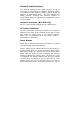
5. Hardware Installation • • • • • For the installation of the (wireless) IP camera it is assumed you have a working network environment. It is highly recommended to first connect the IP camera using a UTP cable instead of directly using the wireless mode (WL-400 only). Connect the UTP cable; use standard UTP cables to connect the camera to one of the LAN ports on your network HUB, switch or router.
restricted to defined the user who has a "User Name" and "User Password" that is assigned by the Administrator. Administrator can release a public user name and password so when remote users access the Internet Camera they will have the right to view the image transmitted by the Internet Camera. Note: Since the default settings are Null String, it is highly recommended to set the "Admin ID" and "Admin Password" when you are the first time to use the Internet Camera.
From the web browser, enter the default IP address to access the Welcome screen of the Internet Camera. To configure your Internet Camera, type http://192.168.0.20 in the address box. This is the default IP address of your Internet Camera. Then, press [Enter]. Note: The PC’s IP address must correspond with the Internet Camera’s IP address in the same segment for the two devices to communicate.
7.1.1 Main Menu Image After the default IP address is entered from the browser, the Internet Camera Welcome screen will appear with a still image. 7.1.2 Configuration Click “Configuration” from the Welcome screen to access the settings required for the Internet Camera.
7.1.3 Configuration – System - System Setting: In this field, you can configure the basic information of your camera. • Camera Name: This field is used to enter a descriptive name for the device. The default setting for the Camera Name is CS-xxxxxx, where xxxxxx is the last six digit of the MAC Address. The maximum length is 32 (printable ASCII). • Location: This field is used to enter a descriptive name for the location used by the camera (optional).
12 (printable ASCII) characters and enter the administrator password with a maximum length of 8 (printable ASCII) characters. It is highly recommended to set the Admin ID and Admin Password as soon as possible to enable security option for the Wireless Internet Camera to function. • LED Control: This option allows user to setup the LED illumination as desired. This feature provides the flexibility when surveillance activity is ON.
7.1.4 Configuration – Video - Video Setting: In this field, you can configure the basic information of your camera. • Video Resolution: Select the desired video resolution format, including 160x120, 320x240 (default) and 640x480. • Compression Rate: Select the desired compression rate with five levels from Very Low to Very High. Higher video compression rate will generate more compact file size with less video quality and vise-versa. The default setting is Medium.
Light Frequency: Adjust the light frequency to suit your area of operation from the options either 50 Hz or 60 Hz (default). Mirror: Using this option it’s possible to flip the screen horizontally or vertically. (eg. When the camera is placed upside-down, the screen can be flipped horizontally.) Anti-flicker: Select this option to reduce flickering of pulsating light sources.
7.1.5 Configuration – Wireless (WL-400 only) Click the Wireless item to setup the wireless LAN configuration of your camera. - Wireless Interface • Connection Mode: Use this option to determine the type of wireless communication for your camera. There are two choices of Infrastructure mode and Ad-Hoc mode. The default setting is Infrastructure. • SSID: The SSID (Service Set Identifier) is the name assigned to the wireless network.
auto-detect and display the SSID of wireless network connected in this box (it displays default initially). This default setting will let the camera connect to ANY access point under the infrastructure network mode. To connect the camera to a specific access point on the network, please make sure to set the SSID of the camera to correspond with the access point’s SSID for communication. Type any string up to 32 characters long (spaces, symbols, and punctuation are not allowed) in the Network Name box.
WEP (Wired Equivalent Privacy) is an encryption method specified by the IEEE 802.11g standard to make any intercepted communications extremely difficult to interpret by unauthorized parties. The default setting for this option is Disable. • WEP Key Format: To enable WEP Encryption, you should decide the encryption format first by selecting the ASCII or HEX option, and then input the WEP key (in the following Key 1~4 box).
WEP key, input 26 HEX format. For example, ‘31323334353637383930313233’, which is the same with ASCII input ‘1234567890123’. These character counts result in bit counts of 40 and 104, respectively; the Wireless Internet Camera will automatically pad your input to a bit count of 64 or 128. • Encrypt Data Transmissions Using: Use this pull-down menu to decide to use Key 1, 2, 3 or 4 for encryption). - WPA PSK: WPA PSK is more secure than WEP.
7.1.6 Configuration – Network - TCP/IP: The items in this field display the information of the wireless LAN, such as the Connection Mode (Infrastructure or Ad-Hoc), Link, SSID, Channel, Transmission Rate, and WEP Encryption. • IP Address Mode: This field provides your with three options to select the IP Address Mode: Fixed IP – You can select this option and enter the IP address directly.
• IP Address – 192.168.0.20 • Subnet Mask – 255.255.255.0 • Default Gateway – 0.0.0.0 Dynamic Address (DHCP) – If your network uses the DHCP server, select this option. According to this setting, the camera will be assigned an IP address from the DHCP server automatically. Every time when the camera starts up, please make sure that the DHCP server is set to assign a static IP address to your camera.
• UPnP: UPnP is the architecture for pervasive peer-to-peer network connectivity of intelligent appliances, wireless devices, and PCs of all form factors. Check the Enable option to enable the function of your camera. 7.1.7 Configuration – User - User Access Control: • Access Control: The administrator has the authority to give permission for the privilege to control the device to users by selecting Enable or Disable. The default setting is No.
selecting Yes or No to activate the Upload/Email Video. To add a new user’s name, enter the necessary information first and click the Add button. • Delete User: Select the user you want to delete from the pull-down menu, and then click the Delete button. • User List: This list displays the current users status of your camera. 7.1.
setting. The time will be synchronized every 10 minutes. When selecting this option, you have to enter the required information in the following fields: IP Address – Enter the IP Address of the Time Server in this box. Protocol – Two options of NTP or Time are available for your selection to link with the Time Server. The default setting is NTP. TimeZone – Select the time zone for the region from the pull-down menu. • Set Manually: Select this option to set the time manually.
- FTP Server: This field contains the following six basic settings for your FTP server. • Host Address: The IP Address of the target FTP server. • Port Number: The standard port number for the FTP server is Port 21, and it’s also the default setting. If the FTP server uses a specific port, please confirm the IT manager. • User Name: Enter the user name in this field. • Password: Enter the user password in this field to login the FTP server.
• Directory Path: Enter an existing folder name in this field, and the images will be uploaded to the given folder. • Passive Mode: This function depends on your FTP server. Please check with your IT manager if the FTP server uses passive mode. The default setting is No. - Time Schedule: Select the “Enable upload video to FTP server” option and enter the relevant information, such as the schedule, video frequency and base file name. • Schedule: You can 1.
- E-mail Account: This field contains the following six basic settings for your FTP server. • SMTP Server Address: SMTP (Simple Mail Transfer Protocol) is a protocol for sending email messages between servers you need to input the mail server address in this field. • Sender e-mail Address: Enter the e-mail address of the user who will send the e-mail. • Receiver e-mail Address: Enter the e-mail address of the user who will receive the e-mail. • User Name: Enter the user name in this field.
- Time Schedule: Select the “Enable-mail video to e-mail account” option to set schedule to send email. Please refer to the instruction in “Upload” section. The Interval option is to define time interval between two images sent. - Manual Operation: When you click the E-mail Video button in view video screen, it will start to e-mail image. The Interval option is to define time interval between two images sent. 7.2.1 Management - System Click the System item to display the device status of your camera.
(network connection), Speed, and the Duplex mode.
7.2.2 Management – Video Click the Video item to display the video configuration of your camera. Video Status: The video configuration about the camera, including the Video Resolution, Compression Rate, Frame Rate, Frame Size and IP Address, can be found in this field.
7.2.3 Management – Wireless (WL-400 only) Click the Wireless item to display the information of the wireless LAN. The items in this field display the information of the wireless LAN, such as the Connection Mode (Infrastructure or Ad-Hoc), Link, SSID, Channel, Transmission Rate, and WEP Encryption.
7.2.4 Management - Network Click the Network item to display the information of the LAN. Network Status: The items in this field display the information of the LAN, such as the IP Address, Subnet Mask, Default Gateway, Primary DNS Address, Secondary DNS Address, Dynamic DNS, Secondary HTTP Port, and UPnP.
7.2.5 Management – Active users Click the User item to display the user(s) information. Active Users: The items in this field display the user(s) information, including the user(s) IP address, Name, and DateTime.
7.3.1 Tools – FTP Server test Click the FTP-server Test item to test your FTP server account settings. Test FTP server: Click the Test button to test the FTP server account you provided.
7.3.2 Tools – E-mail test Click the E-mail Test item to test your e-mail account settings. Test E-mail Account: Click the Test button to test the e-mail account you provided.
7.3.3 Tools – Reset Click the YES button from this option, and you can restart the camera just like turning the device off and on and saved settings are retained. If you do not want to reset the camera, exit this window without clicking YES.
7.3.4 Tools – Factory Click the YES button from this option, and you can resume all factory default settings for the camera. If you do not want to restore the factory settings, exit this window without clicking YES. Please NOTE that you have to configure the network settings again after a Factory Reset.
7.3.5 Tools – Firmware upgrade When a new firmware is available, you can upgrade it through this window. Click the Browse… button to point to the firmware file, and then click Update to start upgrading.
7.3.6 Tools – Backup Click the Backup configuration. item to backup the current - Backup Device Configuration to File: Do you really want to backup the configuration to file? Click the Backup button from this option, and you can save the current configuration to file. - Restore Device Configuration from File: You can resume the device configuration from saved file in the computer. Click the Browse… button to point to the file, and then click Restore to start restoring.
7.4.1 Home – ActiveX To view video images from the browser, click “ActiveX” from the welcome screen to access the video images from Internet Explorer as illustrated below: Camera Name* Date Time** Camera Name* - The Camera name will be display when the Camera Name field is entered in the Web Configuration setting under “Configuration” Date/Time**- The date/time of the video server will show the date and time that come from time server or you set manually.
2. Install to your Local PC In ActiveX, you are allowed two output trigger options and one image upload option. Just click the desired selection “ON” or “OFF” to utilize the options for each of the functions. Note 1: Administrator has the authority to set the email image functions through the setting in the “E-mail” of System Administration menu bar.
7.4.2 View Image – Java Mode Click “Java” from the Welcome screen to access the video images from the Internet Explorer or Netscape browser: Camera Name - The Camera name will be display when the Camera Name field is entered in the Web Configuration setting under “Configuration” In Java you are allowed two output trigger options and one image upload option. Just click the desired selection “ON” or “OFF” to utilize the options for each of the functions.
8. Internet Camera Application The Internet Camera can be applied in wide variety of applications. With the built-in CPU, it can work as a standalone system that provides a web-based solution transmitting high quality video images and sounds for monitoring purposes. It can be managed remotely, accessed and controlled from any PC desktop over the Intranet or Internet via a web browser. With the easy installation procedure, real-time live images will be available.
8.1 Internet Camera Application Diagrams 8.1.
8.1.
9. IPView SE Application 9.1 Installation Insert the CD-ROM into the CD-ROM drive to initiate the auto-run program. Once completed, a menu screen will appear as below: To install the IPView SE application click the "IPView SE" button to activate the installation procedure for the application program.
Once executed, you will be asked to select the desired language. Select the language you want and click “OK” to continue. The Welcome screen will appear as below. Click the “Next” button.
The License Agreement window will appear as below. Read the details carefully and click the “Yes” button. In the following window, you may click “Next” to accept the recommended destination location or click “Browse” to select another location.
specifying the desired destination location, click “Next”. The following window allows you to select the folder where the IPView SE application will be located, click “Next” to continue.
Windows 2000/XP users will see the following window. Click “Continue anyway” to proceed with the installation. Please wait until one of the following two dialog boxes to appear. If the system has to restart, select “Yes, I want to restart my computer now” and click the “Finish” button to complete the installation procedure.
Otherwise, you may simply click the “Finish” button to complete the installation procedure After successfully installing the IPView SE, the application program for the Internet Camera is automatically installed to \Programs\Files directory. To start running the IPView SE, click Start -> Programs -> IPView SE -> IPView SE.
10. Getting Started with IPView This section describes the operation of the IPView SE application with detailed procedures for using the application. IPView SE is responsible for the management of preview, configuration, and searching of each camera. It is designed with a user-friendly interface for ease of control and navigation requirements as illustrated below.
10.
Minimize To minimize the control panel. Exit To close IPView SE. Play To play back the recorded file. Scan To search all of the available internet cameras connected to the LAN. Combine To combine all display windows in one. About To display the information of IPView SE.
10.2 How to Add a Camera Add Camera Add Camera To add a new camera, click the Add Camera button. An Add Camera dialog box will appear as illustrated below. Enter the IP Address of the camera in the specified field and click the “Add” icon to add a new camera.
Note: 1. If you want to add a camera through the Internet, you must key in a physical IP Address. 2. When the camera is installed behind Gateway and the Open Second Port of camera/Port Forwarding of Gateway function is enabled, the Gateway IP address has to be entered with the Port Number as below: 3. At the same time, the Gateway IP address can be replaced by URL as below: 4. If you forget the IP Address that you want to add, a dialog box will appear to notify you of the error.
dialog box will appear with a blank screen as illustrated below. You must select the camera and click the “Add” button to add a new camera. The Add Camera dialog box will appear once again with the IP Address entered. Click the “Add” button, and the camera will be automatically added into IPView SE list view format. If the Login Camera dialog box appears, make sure to enter the correct User Name and Password and click the “OK” button. Then, the camera will be added into IPView SE in list format.
The above dialog box will appear only if administrator has already set up the User Name and Password in the Web Configuration setting. If you forget to highlight the camera you want to add, a dialog box will appear to notify you of the error. Make sure to save any changes you have made to keep the information updated. Note 2: You are allowed to add only one camera at a time.
Camera Config Motion record Assign IP to Camera Schedule record Connect / Disconnect Erase Manual record Extra Information 60
10.3 How to Change Camera Assign IP of New Camera Enter a new IP address in the following dialog box, and it will connect to new camera.
10.4 How to Connect / Disconnect the Image Connect the Image Click the “Connect/Disconnect” button and the preview screen will appear with the video image. Minimize Click to minimize the display screen of the Internet Camera. Maximize Click to maximize the display screen of the Internet Camera.
Close Click to close the display screen of the Internet Camera. Always on top Click to have the display screen always appear on the top of the window. Wake up control panel Click to open the control panel again when it is closed. Color setting Click to adjust color of the image. View list Click to check the event list of the Internet Camera. Snapshot Click to snapshot a picture from the Internet Camera. Rotate image Click to rotate the image of the Internet Camera.
Disconnect the Image Click the “Connect / Disconnect” button again, the camera will be disconnected.
10.5 How to Delete a Camera Erase Camera To delete a camera, you must select the camera to delete from the IPView SE control panel. Then, click the “Erase Camera” button. After deleting the camera, the IPView SE control panel will appear as below.
10.6 Extra Information Extra Information The screen displays the camera’s information.
10.7 How to Adjust the Property Setting System Configure From the control panel, select the button and the dialog box will appear as shown below. Log Storage: 1. Single HDD Reserve Space This option permits reserved space by memory size from 500 MB to 1000 MB. 2.
5MB). If the recorded video files reach the file size, video images will be recorded into another file automatically. By File Size - permits recording by file memory size from 5 MB to 50 MB. 3. Storage List This option is used to define the path to save image files. The software will create a camera name folder as the “Storage List” which is allowed to create up to 4 File Path. Recycle: When you enabled this function, it will recycle the HDD space once the disk space is less than the size defined.
Camera Configure Click the “Camera Config” button and it will active the Camera Setting, Motion Setting and Update Firmware buttons. Camera Setting Motion Setting Update Firmware Camera Setting Please refer to the “Web Configuration” section.
Motion Setting You can adjust the sensitivity level and choose the Invoke Alarm options to work with motion detection function. Besides the Alarm Beep, Send Email can be enabled when motion detected. The user can define the time interval to Send E-mail.
Update Firmware Enter the File Path and click the “Update” button, the firmware will be updated automatically. If you are unsure of the File path, you can click the “Browse” button, the Browse dialog box will appear as illustrated below.
10.8 How to Adjust the Recording Setting There are three ways to start recording image Motion Record, Schedule Record & Manual Record. Motion Record This option allows the camera to trigger recording by motion detected. You can adjust the sensitivity level and choose the warning options when motion is detected from motion setting. Schedule Record This option allows the camera to trigger recording as schedule defined. The schedule is set by date or week day.
Appendix A Frequently Asked Questions Internet Camera Features Q: What is an Internet Camera? A: The Internet Camera is a standalone system connecting directly to an Ethernet or Fast Ethernet network and supported by the transmission based on the IEEE 802.11b standard. It is different from the conventional PC Camera, the Internet Camera is an allin-one system with built-in CPU and web-based solutions providing a low cost solution that can transmit high quality video images for monitoring.
A: The Internet Camera utilizes the JPEG image compression technology providing high quality images for users. JPEG is adopted since it is a standard for image compression and can be applied to various web browser and application software without the need to install extra software. Internet Camera Installation Q: Can the Internet Camera be used out-doors? A: The Internet Camera is not weatherproof. It needs to be equipped with a weatherproof case to be used outdoors and it is not recommended.
A: If a firewall exists on the network, port 80 is open for ordinary data communication. However, since the Internet Camera transmits image data, the default port 8481 is also required. Therefore, it is necessary to open port 8481 of the network for remote users to access the Internet Camera.
B PING Your IP Address The PING (Packet Internet Groper) command can determine whether a specific IP address is accessible by sending a packet to the specific address and waiting for a reply. It can also provide a very useful tool to confirm if the IP address conflicts with the Internet Camera over the network. Follow the step-by-step procedure below to utilize the PING command. However, you must disconnect the Internet Camera from the network first. Start a DOS window. Type ping x.x.x.x, where x.x.x.
C Troubleshooting Q: I cannot access the Internet Camera from a web browser. A1: The possible cause might be the IP Address for the Internet Camera is already being used by another device. To correct the possible problem, you need to first disconnect the Internet Camera from the network. Then run the PING utility (follow the instructions in Appendix B - PING Your IP Address). A2: Another possible reason is the IP Address is located on a different subnet.
Therefore the IP address of the Internet Camera must be set from a workstation on the same subnet. A3: Other possible problems might be due to the network cable. Try replacing your network cable. Test the network interface of the product by connecting a local computer to the unit, utilizing a standard Crossover (hub to hub) Cable. If the problem is not solved the Internet Camera might be faulty. Q: Why does the Power LED not light up constantly? A: The power supply used might be at fault.
A2: The default router setting might be a possible reason. Need to double check if the configuration of the default router settings is required. Q: Why does a series of broad vertical white line appears through out the image? A: A likely issue is that the CMOS sensor becomes overloaded when the light source is too bright such as direct exposure to sunlight or halogen light. You need to reposition the Internet Camera into a more shaded area immediately as this will damage the CMOS sensor.
A2: There might be transmission interference make sure there are no other devices on the network that will affect the transmission. Q: There is poor image quality, how can I improve the image? A1: A probable cause might be the incorrect display properties configuration for your desktop. You need to open the Display Properties on your desktop and configure your display to show at least 65’000 colors for example at least 16-bit.
D Upgrade Firmware The users can update firmware of the IPView SE application. Select “Camera” > “Properties”, and the Camera Property dialog box will appear. Select the Tools tab and enter the full path of the firmware binary file name in the Update Firmware field, or you can click the “Browse” button to select the file. Once the firmware file is entered, click the “Update” button to proceed with the updating process.
E Xplug Control Installation Installation To Web Server Important Information It is highly recommended to install the Xplug Control application to the Web Server for IE 5.0. It must be installed to a Public Domain with Fixed IP address. 1. Installation: Copy the “xplug.ocx” file to any WEB Server table. 2. Setting (Configuration): From the Web Configuration menu select “System” and under the “Loading ActiveX From” input web server location (http://www.web server location.com/).
To install Xplug Control, click the "Xplug Control" button to activate the installation procedure for the plugin program. Once executed, a prompt will appear requesting the input of the desired language selection. Make the desired selection and click “OK” to continue.
The Welcome screen will appear. Click the “Next” button to proceed with the installation. The License Agreement prompt will appear as below. Read the details carefully and click the “Yes” button to continue with the installation procedure.
Click the “Finish” button to complete Setup of the Xplug Control Utility program for the Internet Camera.
F Specifications Video specification Resolution: Sensor: Lens: Gain control: Exposure: White Balance: 640 x 480 pixel Color CMOS sensor f: 6.0 mm, F: 1.8 Automatic Automatic Automatic Image (Video Setting) Image compression: Frame rate: Frame rate setting: Video resolution: JPEG 30fps @ QCIF, 25fps @ CIF, 10fps @ VGA 1, 5, 7, 15, 20, Auto (depends on the video format) 160x120, 320x240, 640x480 Hardware Interface LAN Connector: One RJ-45 port, 10/100M auto-sensed, Auto-MDIX Wireless LAN: Built-in 802.
RAM: 8MB Flash ROM: 2MB OS: RTOS Power Supply: DC 5V, switching type Power consumption: 5 Watt (1000mA x 5V) LED Indicator: Power LED (Blue) Activity LED (Orange) Software Browser: Application Software: OS supported: Internet Explorer 5.0 or above; Netscape 6.0 or above IPView SE Microsoft Windows 98SE/ME/ 2000/XP, Windows NT4.
G Glossary of Terms NUMBERS 10BASE-T 10BASE-T is Ethernet over UTP Category III,IV, or V unshielded twisted-pair media. 100BASETX The two-pair twisted-media implementation 100BASE-T is called 100BASE-TX. 802.11b An IEEE standard for wireless local area networks. It offers transmissions speeds at up to 11 Mbps in the 2.4-GHz band. of A Access point It is the hardware interface between a wireless LAN and a wired LAN. The access point attaches to the wired LAN through an Ethernet connection.
data on the same network by translating an IP address to a physical address. AVI Audio Video Interleave, it is a Windows platform audio and video file type, a common format for small movies and videos. B BOOTP Bootstrap Protocol is an Internet protocol that can automatically configure a network device in a diskless workstation to give its own IP address. C Communica Communication has four components: sender, tion receiver, message, and medium.
of static and dynamic IP addresses. This simplifies the task for network administrators because the software keeps track of IP addresses rather than requiring an administrator to manage the task. This means a new computer can be added to a network without the hassle of manually assigning it a unique IP address.
information, in the form of electrical signals, between devices. Ethernet is an implementation of CSMA/CD that operates in a bus or star topology. F Fast Ethernet Fast Ethernet, also called 100BASE-T, operates at 10 or 100Mbps per second over UTP, STP, or fiberoptic media. Firewall Firewall is considered the first line of defense in protecting private information. For better security, data can be encrypted. A system designed to prevent unauthorized access to or from a private network.
numbers 0 to 9 and the letters A to F. For example, the decimal number 15 is represented as F in the hexadecimal numbering system. The hexadecimal system is useful because it can represent every byte (8 bits) as two consecutive hexadecimal digits. It is easier for humans to read hexadecimal numbers than binary numbers. I IEEE Institute of Electrical and Electronic Engineers.
IP addressing rules. In smaller LANs, most people will allow the DHCP function of a router or gateway to assign the IP addresses on internal networks. IP address IP address is a 32-binary digit number that identifies each sender or receiver of information that is sent in packets across the Internet. For example 80.80.80.69 is an IP address, it is the closet thing the Internet has to telephone numbers.
of buildings. N NAT Network Address Translator generally applied by a router, that makes many different IP addresses on an internal network appear to the Internet as a single address. For routing messages properly within your network, each device requires a unique IP address. But the addresses may not be valid outside your network. NAT solves the problem. When devices within your network request information from the Internet, the requests are forwarded to the Internet under the router's IP address.
PING Packet Internet Groper, a utility used to determine whether a specific IP address is accessible. It functions by sending a packet to the specified address and waits for a reply. It is primarily used to troubleshoot Internet connections. PPPoE Point-to-Point Protocol over Ethernet. PPPoE is a specification for connecting the users on an Ethernet to the Internet through a common broadband medium, such as DSL or cable modem. All the users over the Ethernet share a common connection.
(TCP/IP) suite, forwards packets from one network to another using the same network protocol. R RARP Reverse Address Resolution Protocol, a TCP/IP protocol that allows a physical address, such as an Ethernet address, to be translated into an IP address. RJ-45 RJ-45 connector is used for Ethernet cable connections. Router A router is the network software or hardware entity charged with routing packets between networks.
mask called the subnet mask. T (TCP/IP) Transmission Control Protocol/Internet Protocol is a widely used transport protocol that connects diverse computers of various transmission methods. It was developed y the Department of Defense to connect different computer types and led to the development of the Internet. Transceiver A transceiver joins two network segments together. Transceivers can also be used to join a segment that uses one medium to a segment that uses a different medium.
wires enclosed in an unshielded sheath. W WAN Wide-Area Network. A wide-area network consists of groups of interconnected computers that are separated by a wide distance and communicate with each other via common carrier telecommunication techniques. Windows Windows is a graphical workstations that use DOS.
99