
User Manual

SISTEMATICA S.p.A. Pag. 2/4
Via S. Pertini, 17 – 12030 MANTA (CN) ITALY Tel. +39 0175 255.711 r.a. – Fax +39 0175 255.715
http://www.sistematica.it e-mail: info@sistematica.it
TECHNICAL FEATURES
• Manufacturer: SISTEMATICA S.p.A.
• Dimensions: 80x75x55
• Outputs number: up to 4
• IP protection: IP67
• Operating temperature: -20°C ÷ +70°C
• Power supply voltage: 12/24 V ±10%
• Current consumption: - 18 mA at 12 V
- 14 mA at 24 V
• Max current per channel: 5 A
• Max total current: 20 A
• Communication interface (when applicable): CAN
BUS
• 8 bit microcontroller
• Reverse battery protection
• Internal antenna
SYSTEM CODING
Coding the system is an operation that is only necessary when the receiver has to be replaced or you want to use it
with a different SISTEMATICA radio remote control from the one it is coupled with at the time of purchase.
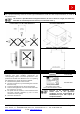
For a correct coding procedure, perform the following steps:
1. Disconnect the power to the receiver;
2. Open the receiver box, by unscreawing the 4 screws fixed on
its top;
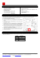
3. Locate and press the coding pushbutton on the receiver board
(blue button – fig. 1);
4. Put power into the receiver by keeping the coding pushbutton
pressed for 3-4 sec.; the yellow led on the receiver board
flashes two time per second; so release the coding pushbutton;
5. Press any 3 keys at the same time on the transmitter within 15
seconds since it has been switched on (also more time if it is
necessary; the yellow led stop to blink);
6. At this time, the transmitter is codified with the reveiver; check
all the system function by trying the movements of the system;
7. Close the receiver box.
Figure 1. Coding pushbutton
WIRING DESCRIPTION
The standard wiring is composed of a cable of lenght L=1mt with a termination in the receiver on one side and free
cables on the other side
COLOR FUNCTION
GREEN EV 1
YELLOW EV 2
GRAY EV 3
PINK EV 4
RED + ALIMENTATION
BLACK - ALIMENTATION