
User's Manual

4
SEM 1 (dis.1)
-
SEM 8
(dis.1a)
Warning! The peripheral exhausting group (remote fitted extraction motor) is built in
class
II (symbol on the rating plate), therefore it must not be
earthed.
The appliance is designed to exhaust fumes and odours very silently and in the best way. It
must be installed in the house and connected to the cooker-hood, which is in the kitchen
(fig.
2)
Types of installation: to make the installation easy, the appliance can be fixed on the wall,
on the ceiling or on the floor in a horizontal position (fig. 3 ) or vertically (fig. 4) to the fixing
level.
Note: in the vertical fixing, the brackets supplied can be used only on the longest side (fig.
6
)
.
Installation of the appliance: after deciding the position and the type of installation, insert the
anti-vibration rubber caps in the holes of the brackets supplied (fig.
5C).
The rubber caps must be put on the sides which are in contact with the wall.
Put the brackets (fig. 5A) on the remote
fitted
extraction motor by matching its holes with those
of the brackets. Fix with the screws supplied (fig.
5B).
Put the group on the point
previously
chosen for the
installation
and mark the points on the wall
where the holes must be drilled.
Insert the dowels supplied in the holes (fig. 6A). Put the remote fitted extraction motor on the
wall by matching the holes of the brackets with the plastic dowels. Screw with the screws
sup
-
plied (fig.
6B).
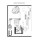
Connection of the pipes: the appliance is endowed with an entrance and an outlet to connect
the pipes. Before connecting the exhaust pipes, check the direction of the air showed on the
external label (fig. 7). Connect the pipes and fix them with appropriate metal clamps
(exhaust
pipes and metal clamps have to be supplied by the installer). The pipe (fig. 7A) must be con
-
nected with the cooker-hood placed in the kitchen, and the pipe (fig. 7B) must be directed
outside the building.
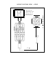
Electrical connection of the hood SEM 1: the appliance is equipped with a 7m electrical
ca
-
ble with a six- pin connection at one end. Insert it into the hood’s connection (External Motor
version)
Electrical connection to the hood SEM 8: the unit is supplied with a pipe 7 meters long. After
having let the cable pass through the plastic pipe (fig. 12E) placed in the wall (fig. 12D), placed
it closed to the unit and connect the 6 poles connector (fig. 12E) and the 2 poles connector
(fig.
12G).