3EM21522AAAA Issue 1, March 2008 Front Matter DTR-0200-SA-SIRIUS FRONT MATTER: Includes the general manual layout by section, customer service center information, telephone technical support information, safety precautions, and warranty/repair information. GENERAL – SECTION 1: Provides a general description of the system to include its purpose and a high level breakdown of components.
NORTH AMERICA CUSTOMER SERVICE CENTER 24 HOURS PER DAY, 7 DAYS PER WEEK PHONE the Call Center at 888-252-2832 (US and Canada) or 613-784-6100 (International) The Call Center Agent (CSA) Will help connect you with Technical Assistance (TAC) Or assist you with a Repair and Return TAC • Phone-based technical support • After-hour emergencies • On-site technical support • E-mail support ml-tac.support@alcatel-lucent.
TAC Technical Assistance Center Telephone Assistance, Normal Working Hours (CST 8am 5pm M-F) TAC supports all Alcatel North America Microwave products. This includes routine questions and emergency service. Telephone Assistance, Emergency After-Hours • Defined as loss of traffic, standby equipment, or network visibility on traffic-bearing systems. • Available through our Customer Service Agents (CSA).
Front Matter DTR-0200-SA-SIRIUS 3EM21522AAAA Issue 1, March 2008 SAFETY PRECAUTIONS Personnel should use caution when installing, testing, operating, and servicing this equipment. As with all electronic equipment, care should be taken t avoid electrical shock where substantial currents or voltages may be present. Definitions of Danger, Warnings, Cautions, and Notes used throughout this manual are described below. An operating procedure, practice, etc.
3EM21522AAAA Issue 1, March 2008 Front Matter DTR-0200-SA-SIRIUS ELECTRICAL SAFETY: GENERAL RULES Carefully observe the specific procedures for installation, turnup, and maintenance where AC or DC power is present and observe the following general information/rules. • Remove rings, watches, and other metal jewelry. Short circuits in low-voltage, lowimpedance DC circuits can cause severe arcing that my result in burns or eye injury. Exercise caution to avoid shorting power input terminals.
Front Matter DTR-0200-SA-SIRIUS 3EM21522AAAA Issue 1, March 2008 MODULE HANDLING To minimize risk of damage to an ESS device: • All modules should be handled as static sensitive devices • Heel straps are only effective while standing on conductive or static dissipative surfaces • Ground straps, either wrist (PN 055-9357-010) or heel (PN 055-9357-020), should be worn prior to and while touching or handling modules containing ESS devices.
3EM21522AAAA Issue 1, March 2008 Front Matter DTR-0200-SA-SIRIUS MODULE RETURN Call Repair and Return Customer Service Agent (CSA) at 1-888-252-2832 • To receive a Return Authorization (RA) number • For Emergency Orders • For Advance Replacement Please follow this procedure when returning equipment: For the unit(s) to be repaired, include the following information • Serial Number of the part • Company name, billing and shipping address, phone number, and contact name(s) • Description of all known facts a
FM--8 This page intentionally left blank.
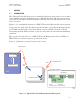
3EM21522AAAA Issue 1, March 2008 General DTR-0200-SA-SIRIUS 1 GENERAL 1.1 INTRODUCTION The Terrestrial Satellite Repeater is a modular solid-state device that receives audio/ video multiplexed data transmissions via a SIRIUS Satellite. The repeater then processes the received data and retransmits it through tower mounted antennas to end users’ receivers. Figure 1 - 1 is a simplified diagram of a SIRIUS Terrestrial Repeater broadcast system.
General DTR-0200-SA-SIRIUS 3EM21522AAAA Issue 1, March 2008 TRANSMIT ANTENNA CDDS Signal From Satellite COFDM RF Signal To Customer VSAT + LNB Antenna REPEATER GPS Antenna Customer Equipment PSTN Alarms to NMS DTR-1001 02/22/07 Figure 1 - 2 Typical Sirius Terrestrial Repeater Site 1.
3EM21522AAAA Issue 1, March 2008 1.
General DTR-0200-SA-SIRIUS 3EM21522AAAA Issue 1, March 2008 Figure 1 - 3 Front View of the Terrestrial Repeater Figure 1 - 4 Rear View of the Terrestrial Repeater 1-4
3EM21522AAAA Issue 1, March 2008 1.4 General DTR-0200-SA-SIRIUS DIGITAL TERRESTRIAL REPEATER NAMING CONVENTION DTR-0200-SA-SIRIUS Mobile TV Standard DVB-T/H DAB DMB-S/T/H Eurika 147 ISDBT FLO CUST (Custom COFDM Waveform) SIRIUS… Proprietary Signal Method of Cooling A = Air Cooled L = Liquid Cooled Frequency Band V U L S = = = = VHG Band III (174 to 230 MHz) UHF (470 to 862 MHz) L-Band (~1.4 to 1.7 GHz) S-Band (~2.1 to 2.
General DTR-0200-SA-SIRIUS 1.5 3EM21522AAAA Issue 1, March 2008 SYSTEM CONFIGURATIONS At the selected site the repeater can be mounted one of three ways: • ground mount • roof mount • shelf mount The repeater electrical and physical configuration is the same for either mounting. 1.6 TERRESTRIAL REPEATER TECHNICAL SPECIFICATIONS Table 1-1 Physical, Electrical, and Environmental Specifications Weight Approx. 121 kg (266 lbs.) Dimensions 60.10 x 102.55 x 67.63 cm / 26.81 x 36 x 40.38 x 26.63 in.
3EM21522AAAA Issue 1, March 2008 General DTR-0200-SA-SIRIUS Table 1-2 Transmitter RF Output Performance Operating Frequency 2326.25 MHz Bandwidth 4.012 MHz Rated Output Power +53.0 dBm Output Power Set Point Range 10 dB Step Size 0.5 dB Output Level Stability vs. Time ≤ -0.25 dB/24 hrs. max Output Level Accuracy ≤ ±0.
General DTR-0200-SA-SIRIUS 3EM21522AAAA Issue 1, March 2008 Table 1-4 Repeater Signal Inputs VSAT Ku Band (L-Band after LNB) Frequency Range 950 – 2150 MHz Nominal Input Level -65 to -25 dBm Waveform S1, S2 LNB Bias Provided Connector F-type, female, 75 ohms Ethernet Input Signal IP multicast, standard 10/100 Base T interface Connector RJ45 ASI Input Connector BNC, 75 ohms Table 1-5 Signal Processing Aggregate Data Rate 7.340625 Mbps COFDM nominal bandwidth used 4.
3EM21522AAAA Issue 1, March 2008 General DTR-0200-SA-SIRIUS Table 1-6 Repeater Test Ports Repeater Out Forward Power Connector: N-type, female, 50 ohms, Coupling: -50 dB Repeater Out Reflected Power Connector: N-type, female, 50 ohms, Coupling: -40 dB HPA RF Monitor Connector: N-type, female, 50 ohms, Coupling: -50 dB Upconverter RF Out Monitor Connector: SMA, female, 50 ohms, Coupling: -20 dB Table 1-7 Repeater Test Modes CW Signal COFDM spectrum replaced by a single carrier 4kHz aside from the
General DTR-0200-SA-SIRIUS 3EM21522AAAA Issue 1, March 2008 HPA PDU SPU Front View DTR-1074 07/30/07 Figure 1 - 5 Components Location (Sheet 1 of 2) HPA Junction Box BP Filter Filter Assembly (inside of door) RF Coupler and Detectors Rear View Figure 1 - 5 Components Location (Sheet 2 of 2) 1-10 DTR-1075 07/30/07
3EM21522AAAA Issue 1, March 2008 2 FUNCTIONAL DESCRIPTION 2.1 GENERAL Functional Description DTR-0200-SA-SIRIUS This section presents a functional description of the Sirius Terrestrial Repeater. 2.2 SYSTEM FUNCTIONAL OVERVIEW Figure 2 - 1 shows the basic Repeater Simplified Functional Block Diagram. The Sirius Terrestrial Repeater transmits at the 2.3265 GHz frequency with a 4.012 MHz signal bandwidth. Refer to the tables in Section 1 for the technical characteristics and the major components. 2.2.
2-2 This page intentionally left blank.
GPS VSAT L N B Local CLI (serial) DB8 IF Test I & Q BNC 50 Ohm Repeater Cabinet RF Test SMA-F RF Fwd Test N (F) RF Refl Test N (F) ASI DVB-S/S2 Receiver F Type Control Core IF I DSP Core Output Coupier UpConverter BPF HPA RF Out (200W) 7-16 DIN (F) To Antenna IF Q Modulator RF Fwd Modulator Control RF Fwd Main Controller Board GPS Receiver N(F) Local Ethernet RJ-45 Local CLI (serial) DB-9 POTS RJ-11 Up-Converter Control Main Controller Ethernet Switch Supervisor Processor HPA C
2-4 This page intentionally left blank.
3EM21522AAAA Issue 1, March 2008 2.3 Functional Description DTR-0200-SA-SIRIUS MAIN FUNCTIONS The Sirius Terrestrial Repeater consists of the following main functions: • Receiver – Receives the down converted input signal from the VSAT Antenna/ LBN via coax cable. Processes the received signal for transmission to the modulator.
Functional Description DTR-0200-SA-SIRIUS 3EM21522AAAA Issue 1, March 2008 Figure 2 - 2 Signal Processing Unit (SPU) 2-6
Figure 2 - 3 Sirius Signal Processing Unit (SPU) Functional Block Diagram 2-7
2-8 This page intentionally left blank.
3EM21522AAAA Issue 1, March 2008 2.3.1.1 Functional Description DTR-0200-SA-SIRIUS L-Band (VSAT) Receiver The VSAT L-Band receiver connector panel is shown in Figure 2-4. The receiver module is located on the SPU sub-assembly. The module receives the DVB-S/S2 signal data stream (which carries the SIRIUS proprietary CDDS) from the L-band LNB module located on the Ku-band VSAT antenna. The receiver processes the down-converted L-band signal by DVB-S/S2 transport stream removal and data recovery.
Functional Description DTR-0200-SA-SIRIUS 3EM21522AAAA Issue 1, March 2008 Figure 2 - 5 Modulator Module 2.3.1.3 Up-Converter Figure 2 - 6 shows the up-converter panel. The up-converter converts the modulator IF (I and Q channels) output to S-Band. An up converter controller applies DAC-controlled DC offset to each IF channel, attenuates and filters the channels, and then sends them to the up-converter for S-Band frequency con-version. The 2.
3EM21522AAAA Issue 1, March 2008 Functional Description DTR-0200-SA-SIRIUS Control commands for status requests and operating parameter modifications from the operator interfaces are received and processed by the main controller. The controller reports problem conditions through dedicated interfaces and also indicates current status and alarms via front panel LEDs. Repeater identity can be configured remotely or locally via the controller.
Functional Description DTR-0200-SA-SIRIUS 3EM21522AAAA Issue 1, March 2008 Back-up Test – continuous self-monitoring of controller and all subsystems. Anomalies are reported to NMC. Major faults cause the controller to shut down the repeater Heartbeat – a special trap/message is transmitted regularly (transmission inter-val set by user via GUI, See Figure 5-34 in Section 5) to the NMC.
3EM21522AAAA Issue 1, March 2008 Functional Description DTR-0200-SA-SIRIUS Figure 2 - 8 Main Controller Board Functional Block Diagram 2-13
Functional Description DTR-0200-SA-SIRIUS 2.3.1.4.1 3EM21522AAAA Issue 1, March 2008 Main Controller Microprocessor Chip The MPC860 microprocessor performs all site management to include control of the GPS receiver, modem, and L-band DVB-S/S2 receiver. The controller also communicates with the SPU modules and on-board components via dedicated interfaces using soft-ware defined protocols.
3EM21522AAAA Issue 1, March 2008 Functional Description DTR-0200-SA-SIRIUS • RF Power: Monitoring is two channel and RS485 full duplex. The path is from the reflected power and forward power detectors through DB9-M panel connector P6B into the processors UART1 and UART2. The Atmega256 processor initializes the GPS Receiver, makes all necessary settings and then monitors important stats (refer to GPS Receiver below). 2.3.1.4.
Functional Description DTR-0200-SA-SIRIUS 3EM21522AAAA Issue 1, March 2008 A manual ON/OFF control switch is located on the front panel of the UPS and allows the unit to be manually switched on or off. This is used primarily by maintenance technicians when servicing the repeater. An internal automatic ON/OFF switch switches the unit off when the +5 or 3.3 input voltages drop. This prevents back current feed to the power supply. The UPS has a 3-wire interface for connection of an optocoupled AC sensor.
3EM21522AAAA Issue 1, March 2008 2.4 Functional Description DTR-0200-SA-SIRIUS HIGH POWER AMPLIFIER (HPA) See Figure 2 - 10 and Figure 2 - 11 for the HPA sub-assembly front and rear panels and the HPA functional block diagram. The HPA amplifies the S-Band terrestrial signal to an output level of 200 watts (after the output filter).
Functional Description DTR-0200-SA-SIRIUS 3EM21522AAAA Issue 1, March 2008 SIRIUS HPA BLOCK DIAGRAM J1 RF INPUT J2 FWR PWR MONITOR J3 RF OUTPUT 50dB J4 CONTROL RF Output Coupler 40dB 50dB 5-WAY OUTPUT COMBINER 3-WAY SPLITTER Preamplifier Temperature Sensing DC BIAS OUT Output Pwr HPA CONTROLLER Monitor 20dB DC & CONTROL Output Pwr Monitor & DC IN Control RS422 DC IN J5 Power Supply AC INPUT DTR-1013 03/10/07 Figure 2 - 11 HPA Functional Block Diagram 2-18
3EM21522AAAA Issue 1, March 2008 Functional Description DTR-0200-SA-SIRIUS 2.4.1 HPA CONTROLLER The HPA Controller monitors various parameters and reports current values and summary alarms to the repeater main controller via the RS485 interface.
Functional Description DTR-0200-SA-SIRIUS 2.4.3 3EM21522AAAA Issue 1, March 2008 HPA PREAMPLIFIER (PREDRIVER) The pre-driver is the first amplifying stage of the HPA. It employs three stages of amplification-a Monolithic Microwave Integrated Circuit (MMIC) amplifier and two LDMOS transistors. The pre-driver raises the output power of the RF from the upconverter by 38 dB and feeds the amplified RF into the HPA driver amplifier.
3EM21522AAAA Issue 1, March 2008 2.5 Functional Description DTR-0200-SA-SIRIUS S-BAND OUTPUT FILTER The output filter is a bandpass filter and provides attenuation of the out-of-band emissions generated by the HPA. The attenuation is to comply with the requirements of TN-SPEC-2.1.0, Terrestrial Network Technical Specification, Transmitter RF Emissions. 2.6 OUTPUT COUPLER The output coupler, connected to the output port of the transmit filter, is the final component in the transmitter chain.
Functional Description DTR-0200-SA-SIRIUS 3EM21522AAAA Issue 1, March 2008 AUX PWR AUX OUTLET EXT HTR INT HTR FANS MAIN PWR HPA UPS HPA POWER SUPPLY VSAT RX MODULATOR SPU MAIN CONTROLLER UP-CONVERTER DTR-1009 03/06/07 Figure 2 - 12 Simplified Block Diagram of Main Power Paths 2-22
3EM21522AAAA Issue 1, March 2008 Functional Description DTR-0200-SA-SIRIUS Figure 2 - 13 Power Distribution Unit (Sheet 1 of 2) 2-23
Functional Description DTR-0200-SA-SIRIUS 3EM21522AAAA Issue 1, March 2008 Figure 2 - 13 Power Distribution Unit (Sheet 2 of 2) 2.8 JUNCTION BOX ASSEMBLY The junction box is mounted on the floor of the cabinet just behind the rear door. It is the interface for the external connections for the AC power line, the VSAT antenna, the GPS antenna, and the telephone line.
3EM21522AAAA Issue 1, March 2008 3 INSTALLATION 3.1 INTRODUCTION Installation DTR-0200-SA-SIRIUS This section describes the installation of Alcatel-Lucent’s Sirius Digital Terrestrial Repeater, DTR-0200-SA-SIRIUS, Alcatel-Lucent part number 3EM04000AA and associated antennas at a designated site. This equipment is to be installed in a restricted access location. 3.2 SAFETY ON SITE 3.2.1 Installation Safety Installation shall be performed by trained, qualified personnel.
Installation DTR-0200-SA-SIRIUS 3.2.4 3EM21522AAAA Issue 1, March 2008 Physical Safety 1. The repeater will be secured to the building/pad before operation. 2. Installation crew members must wear hard hats during installation. 3. A minimum of two technicians is required for any lifting and/or positioning of the repeater cabinet. 3.
Notes: 1. The repeater must be powered directly from a 240v ac service panel with 40 amp UL listed circuit breakers. 2. The green ground wire is to be connected to a safety ground derived from a copper ground plane or rod. 3. A 4-conductor #8 power cable with rubber jacket rated at 90 C will be used. 4. The ac power wiring design and installation must conform to all local and national electrical codes.
3-4 This page intentionally left blank.
3EM21522AAAA Issue 1, March 2008 3.5 Installation DTR-0200-SA-SIRIUS REPEATER UNPACKING AND INSPECTION The repeater equipment containers and the Fibergrate platform containers (or whatever platform is being utilized) should be unpacked and inspected at the earliest date to ensure that all required material has been received and is in good condition. Equipment should be checked against packing lists and site drawings. 3.5.
Installation DTR-0200-SA-SIRIUS 3.9.2 3EM21522AAAA Issue 1, March 2008 External Cables and Connections Prior to making any external connections, ensure that main power to the repeater is turned off at the source and a “Warning, Do Not Turn On, Personnel Working” sign is hanging on the main source power switch. 3.9.2.1 External Connection Current Ratings EXTERNAL CONNECTION 3.9.2.2 MAX CURRENT External Heater Connection Max. Current 1.7A @ 120 VAC Auxiliary Power Outlet Max.
3EM21522AAAA Issue 1, March 2008 3.9.2.6 Installation DTR-0200-SA-SIRIUS Telephone Line (TELCO) Connections To reduce the risk of fire, use only No. 26 AWG or larger (e.g., 24 AWG) UL Listed or CSA Certified Telecommunication Line Cord. TELCO will determine the type and length of cable to be used. Connection will be to the TELCO connector located on the rear panel of the SPU. 3.9.2.7 Electrical Service Connection Refer to Paragraph 3.4, SITE POWER.
3-8 This page intentionally left blank.
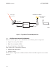
Figure 3 - 2 Repeater Interconnection Diagram 3-9
3-10 This page intentionally left blank.
3EM21522AAAA Issue 1, March 2008 3.10 Installation DTR-0200-SA-SIRIUS POST-INSTALLATION INSPECTION/TEST Post installation inspecting/testing is described below as phase one, two, and three inspecting and/or testing. Phase one and two inspecting/testing is to satisfy the site owner that the system conforms to the owner’s requirements.
3-12 This page intentionally left blank.
3EM21522AAAA Issue 1, March 2008 3.
3-14 This page intentionally left blank.
3EM21522AAAA Issue 1, March 2008 Turn-Up and Testing DTR-0200-SA-SIRIUS 4 TURN-UP AND TESTING 4.1 GENERAL This section describes the procedures required to turn-up and test the DTR-0200-SASIRIUS repeater (ALU Part Number 3EM04000AA) after replacement of the Signal Processor Unit (SPU), software upgrading, and/or other maintenance. These procedures consist of repeater provisioning and field testing. These procedures require GUI software screen access.
Turn-Up and Testing DTR-0200-SA-SIRIUS 4.3 3EM21522AAAA Issue 1, March 2008 REPEATER PROVISIONING Provisioning is the process of checking, changing, and/or installing parameter values to allow the repeater to operate from its assigned location. Normally, no parameter changes will be required except after replacement of the SPU. 4.
3EM21522AAAA Issue 1, March 2008 2 Turn-Up and Testing DTR-0200-SA-SIRIUS Set up the test system as shown in Figure 4 - 2. Ku Band Antenna Antenna Sirius Repeater LNB DVB/S Signal VSAT In RF Out Fw MON 208V AC Power Meter Ethernet Test PC The input power value can be anywhere from 188 to 250 VAC depending on the available site power. DTR-1070 03/16/08 Figure 4 - 2 Field Test Setup For Terrestrial Repeater • Connect the power meter to the FWD RF MONITOR connector on the junction box panel.
Turn-Up and Testing DTR-0200-SA-SIRIUS 3EM21522AAAA Issue 1, March 2008 • The Ethernet connection for the PC is on the back panel of the Main Controller (one of the Ethernet ports in the four port block). See Figure 4 - 4. Figure 4 - 4 Ethernet Ports on Main Controller Back Panel • The input power value can be anywhere from 188 to 250 VAC depending on the available site power. 4.4.2 Operating Mode 1 Power up the repeater. 2 Wait 5 minutes (after the Main Controller finishes initialization).
3EM21522AAAA Issue 1, March 2008 4.4.3 Turn-Up and Testing DTR-0200-SA-SIRIUS Alarm Checking 1 Access to Alarm Log and read system faults/alarms from controller (see Figure 4 - 6). 2 No fault/alarm shall be reported other than Cabinet Rear Door Open. This alarm will appear because of the PC connection to the rear panel of the Main Controller.
Turn-Up and Testing DTR-0200-SA-SIRIUS 4.4.4 3EM21522AAAA Issue 1, March 2008 Software/Firmware Configuration Test 1 Access the Global Status screen. 2 Check and record software/firmware versions used in the repeater. Figure 4 - 7 Global Status Screen 3 4-6 The version numbers shall match those defined by the repeater configuration.
3EM21522AAAA Issue 1, March 2008 4.4.5 Turn-Up and Testing DTR-0200-SA-SIRIUS VSAT Receiver Test 1 View the Global Status screen. 2 Confirm that the receive antenna is correctly pointed at the satellite (determined by VSAT Receiver Signal Strength reading on GUI screen). 3 Ensure that the receive antennas are correctly pointed at the satellite (determined by signal strength reading on GUI screen). 4 If necessary, reconfigure the repeater VSAT receiver to match the satellite signal.
Turn-Up and Testing DTR-0200-SA-SIRIUS 3EM21522AAAA Issue 1, March 2008 Figure 4 - 8 Modulator Mode Screen 5 Set RF output power to +53.0 dBm, and measure the RF output power at the junction box forward coupled jack, CPL FWR, with power meter. The measured RF power level shall be within ±0.5 dB from the set RF power level indicated on the GUI Global Status screen. 6 Remove the power meter from the FWD RF MONITOR connector. No alarm shall be reported other than door(s) open. 4.
3EM21522AAAA Issue 1, March 2008 4.6 Turn-Up and Testing DTR-0200-SA-SIRIUS FIELD TEST REPORT FIELD TEST REPORT SITE: DATE OF TEST: TEST TECHNICIAN Printed Name: COMPANY: Printed Name: COMPANY: Test Requirement Alarm Check No fault/alarm Firmware Configuration Match versions in SPU, Controller, and HPA VSAT Receiver S/N ratio>10dB GPS Receiver 1 ppm and 10MHz present Output Power Within ±0.
4-10 This page intentionally left blank.
3EM21522AAAA Issue 1, March 2008 5 OPERATION 5.1 GENERAL OPERATION DTR-0200-SA-SIRIUS This section addresses control, communication, and parameter modifications of the DTR-0200-SA-SIRIUS terrestrial repeater. It also provides descriptions of controls, indicators, test points, and connectors for the repeater. Refer to Paragraph 5.7 for repeater operating procedures. Refer to Paragraph 5.8 for controls and indicators. 5.
OPERATION DTR-0200-SA-SIRIUS 3EM21522AAAA Issue 1, March 2008 mode prevents a remote operator from accidentally turning on the HPA from the remote site and applying high RF level from the repeater. This could seriously injure the technician working on the repeater at the local site and/or damage the repeater. 5.3 MODES OF OPERATION There are two main parameter groups which determine the operating mode. They are the Repeater Operating Mode parameter group and the Modulator Operating Mode parameter group.
3EM21522AAAA Issue 1, March 2008 OPERATION DTR-0200-SA-SIRIUS The operating conditions in the Standby mode are: • AC power is applied to the SPU, HPA, and fans. • The HPA power supply is disabled. • The HPA RF switch is OFF. • The Up-converter output is muted. • The cabinet fans are turned on. 5.3.1.3 Manual Mode This mode allows manual control of the repeater for the technician to perform maintenance and/or testing or troubleshooting.
OPERATION DTR-0200-SA-SIRIUS 5.4 3EM21522AAAA Issue 1, March 2008 GRAPHICAL USER INTERFACE (GUI) The GUI WEB interface uses a PC for maintenance and support of the repeater, and for fault and status reporting. The interface uses a simple hierarchical menu structure which is user friendly and provides access to parameters. The parameters are classified in five categories; Status, Configuration, Alarms, NMS User, and System Parameter.
3EM21522AAAA Issue 1, March 2008 OPERATION DTR-0200-SA-SIRIUS GUI CONTROLLER MAIN MENU Status Config Global Status GPS Status Up-Converter Cabinet Alarms Modulator VSAT Repeater Output Level Coupler GPS Temperature Repeater Operating Mode PPP Dial In Parameters PPP Dial Out Parameters PPP Misc Parameters Site Alarm Properties Clear Logs Alarm Status NMS Users User Properties System Parameters Identification Access Control Network Parameters SNMP Parameters Heartbeat Time System Reset Upgrade Repea
OPERATION DTR-0200-SA-SIRIUS 3EM21522AAAA Issue 1, March 2008 Their individual GUI screens follow.
3EM21522AAAA Issue 1, March 2008 OPERATION DTR-0200-SA-SIRIUS Figure 5 - 4 GPS Status Screen 5-7
OPERATION DTR-0200-SA-SIRIUS 3EM21522AAAA Issue 1, March 2008 Figure 5 - 5 Up-Converter Status Screen Figure 5 - 6 Cabinet Status Screen 5.5.2 Configuration (Config) Sub-Menu Breakdown Configuration screens allow modification of the parameters according to operator requirements.
3EM21522AAAA Issue 1, March 2008 OPERATION DTR-0200-SA-SIRIUS Figure 5 - 7 GUI Main Menu Config Drop-Down Menu Config Modulator breaks down into a further sub-menu as follows: Repeater ID Modulator Mode Overlay Delays Modulator IP To access the Modulator sub-menu; GUI Main Menu=>Config=>Modulator=> (submenu selection). See Figure 5 - 8.
OPERATION DTR-0200-SA-SIRIUS 3EM21522AAAA Issue 1, March 2008 Figure 5 - 9 through Figure 5 - 13 show the individual screens accessed via the Config Modulator sub- menu. Figure 5 - 9 Repeater ID Screen The Modulator Mode screen, Figure 5 - 10, allows changeover from Repeater Operating Mode to Modulator Operating Mode (refer to para Paragraph 5.3.2).
3EM21522AAAA Issue 1, March 2008 OPERATION DTR-0200-SA-SIRIUS I Figure 5 - 10 Modulator Mode Screen 5-11
OPERATION DTR-0200-SA-SIRIUS 3EM21522AAAA Issue 1, March 2008 Figure 5 - 11 Overlay Screen 5-12
3EM21522AAAA Issue 1, March 2008 OPERATION DTR-0200-SA-SIRIUS Figure 5 - 12 Delays Screen Figure 5 - 13 Modulator IP Screen 5-13
OPERATION DTR-0200-SA-SIRIUS 3EM21522AAAA Issue 1, March 2008 The remainder of the Config menu displays the following screens: VSAT Repeater Output Level Coupler GPS Temperature Repeater Operating Mode PPP Dial In Parameters PPP Dial Out Parameters PPP Misc Parameters Site Figure 5 - 14 through Figure 5 - 23 show the individual aforementioned screens accessed via the Config menu.
3EM21522AAAA Issue 1, March 2008 OPERATION DTR-0200-SA-SIRIUS Figure 5 - 15 Repeater Output Level Screen Figure 5 - 16 Coupler Screen 5-15
OPERATION DTR-0200-SA-SIRIUS 3EM21522AAAA Issue 1, March 2008 Figure 5 - 17 GPS Screen 5-16
3EM21522AAAA Issue 1, March 2008 OPERATION DTR-0200-SA-SIRIUS Figure 5 - 18 Temperature Screen 5-17
OPERATION DTR-0200-SA-SIRIUS 3EM21522AAAA Issue 1, March 2008 Figure 5 - 19 Repeater Operating Mode Screen 5-18
3EM21522AAAA Issue 1, March 2008 OPERATION DTR-0200-SA-SIRIUS Figure 5 - 20 PPP Dial In Parameters Screen 5-19
OPERATION DTR-0200-SA-SIRIUS 3EM21522AAAA Issue 1, March 2008 Phone Number String – Always begin with ATDT then add phone number of NMC. If required, precede number with external line prefix. Modem Connection Timeout – For dial out reliability do not use less then 120.
3EM21522AAAA Issue 1, March 2008 OPERATION DTR-0200-SA-SIRIUS Figure 5 - 22 PPP Misc Parameters Screen 5-21
OPERATION DTR-0200-SA-SIRIUS 3EM21522AAAA Issue 1, March 2008 Figure 5 - 23 Site Screen 5.5.3 Alarms Sub-Menu Breakdown Alarms shows the repeater current alarm status, alarm log, and allows the user to configure alarms according to user requirements.
3EM21522AAAA Issue 1, March 2008 OPERATION DTR-0200-SA-SIRIUS The Alarm sub-menus are divided as follows: Alarm Properties Clear Log File Alarm Status The individual GUI screens follow. Integration Time = Time in seconds that the repeater software will sample the condition causing the alarm - to make sure the cause is present during the whole period of time. This is used when the alarm changes from Cleared to Set. Value 0 means that the first time the condition is detected, the alarm will be set.
OPERATION DTR-0200-SA-SIRIUS 3EM21522AAAA Issue 1, March 2008 Figure 5 - 26 Alarm Status Screen 5.5.4 NMS Users Sub-Menu Breakdown The NMS Users screen shows identification and authorization parameters. To access the NMS Users sub-menu; GUI Main Menu => NMS Users => User Properties. See Figure 5 - 27.
3EM21522AAAA Issue 1, March 2008 OPERATION DTR-0200-SA-SIRIUS 5.5.5 System Parameters Menu To access the System Parameters sub-menu: GUI Main Menu=>System Parameters. See Figure 5 - 28.
OPERATION DTR-0200-SA-SIRIUS 3EM21522AAAA Issue 1, March 2008 The individual GUI screens follow: Figure 5 - 29 System Parameters Identification Screen Figure 5 - 30 System Parameters Access Control Screen 5-26
3EM21522AAAA Issue 1, March 2008 OPERATION DTR-0200-SA-SIRIUS Figure 5 - 31 System Parameters Network Parameters Screen Figure 5 - 32 System parameters SNMP Parameters Screen 5-27
OPERATION DTR-0200-SA-SIRIUS 3EM21522AAAA Issue 1, March 2008 Figure 5 - 33 System Parameters System Time Screen 5-28
3EM21522AAAA Issue 1, March 2008 OPERATION DTR-0200-SA-SIRIUS The Heartbeat screen allows the user to set the Heartbeat transmission interval to the NMC Heartbeat Hour Start* Reference hour from the current day Heartbeat Minute Start* Reference minute Heartbeat Pace Interval in minutes that the heartbeat traps are generated. Warning A Heartbeat pace of less than 10 minutes could prevent remote dial-in and possibly require local access in order to perform any reconfiguration.
OPERATION DTR-0200-SA-SIRIUS 3EM21522AAAA Issue 1, March 2008 Figure 5 - 35 System Parameters System Reset Screen The Upgrade screen allows the operator to upgrade system components by using the Browse button to select the proper upgrade file (e.g.; Main Controller, Supervisor Controller, VSAT Controller, Modulator [PPCO, PPCI, DSP, FPGA], Up-Converter, HPA). After file selection, click on “Start Download”. See Figure 5 - 36.
3EM21522AAAA Issue 1, March 2008 OPERATION DTR-0200-SA-SIRIUS As upgrade starts, a pop-up dialog box displays with the current upgrade status information. See Figure 5 - 37. Screen may be slow to display status.
OPERATION DTR-0200-SA-SIRIUS 3EM21522AAAA Issue 1, March 2008 The web server is a single threaded server, and as such, allows only one connection at a time. This means an upgrade via phone line can take 10 minutes or more for file transfer. This is dependent upon speed and file size. During transfer, the pop-up dialog box remains blank and only starts showing information after the file is completely transferred. 5.
3EM21522AAAA Issue 1, March 2008 OPERATION DTR-0200-SA-SIRIUS At login, the default password is “admin.” This can be changed through the Web password parameter. Figure 5 - 40 CLI Main Menu Screen 5.7 REPEATER OPERATING PROCEDURES 5.7.1 Local/Remote Operation The repeater can be controlled and monitored either locally on site or remotely from a network management center (NMC). The SPU front panel LOCAL REMOTE switch controls the operating mode of the repeater.
OPERATION DTR-0200-SA-SIRIUS 5.7.1.1 3EM21522AAAA Issue 1, March 2008 Local Operation For repeater local control (during initial setup and/or maintenance sessions, etc.) and status information, a PC can be connected to the LAN and established via the Ethernet (RJ45) port which provides access to the Web and GUI interface. This is the preferred method. An alternate access method is via the RS-232 (DB9) serial port using the Command Line Interface (CLI) protocol.
3EM21522AAAA Issue 1, March 2008 5.7.1.3 OPERATION DTR-0200-SA-SIRIUS Steps to Access the Repeater in Local Operating Condition via Ethernet 1. Connect the PC to the Ethernet (RJ45) port on the back panel of the controller. See Figure 5 - 42. Figure 5 - 42 Main Controller Back Panel Ethernet Connection 2. Access the repeater using the Internet Explorer browser and the repeater IP address. When the repeater finishes booting, the Login screen displays. See Figure 5 - 43. Figure 5 - 43 Login Screen 3.
OPERATION DTR-0200-SA-SIRIUS 5.7.1.4 3EM21522AAAA Issue 1, March 2008 Steps to Access the Repeater in Local Operating Condition via RS-232 1. Connect PC to RS-232 Console Port (SPU front panel) using a straight cable. 2. Access the repeater via the HyperTerminal and using CLI commands. The Modulator can also be directly accessed using an RS-232 Null Modem cable connected to the Modulator RS-232 LOCAL PORT connector on the modulator back panel, and using CLI commands. 5.7.1.
3EM21522AAAA Issue 1, March 2008 OPERATION DTR-0200-SA-SIRIUS Figure 5 - 44 Repeater Operating Mode Screen 5.7.2.1.1 Standby Mode The Standby Mode is used to take the repeater off the air without removing all power. The up-converter output is muted, ALC is off, and the HPA is switched off by disabling the HPA power supply.
OPERATION DTR-0200-SA-SIRIUS 5.7.2.1.3 3EM21522AAAA Issue 1, March 2008 Manual Mode The Manual Mode is for testing and troubleshooting. Refer to the Maintenance section of this manual for use of the Manual Mode. When switched to the Manual mode, the repeater maintains all the system settings that were in effect in the previous mode. Table 5-1 summarizes the repeater status under the three modes of operation.
3EM21522AAAA Issue 1, March 2008 5.7.2.2 OPERATION DTR-0200-SA-SIRIUS Modulator Modes There are seven modulator operating modes but only two are used in the field; the remainder are factory modes. The two modes used by the operator/technician are: 1). Standby mode 2). Run Mode selection is via the GUI Main Menu. From the Main Menu select Config =>Modulator => Modulator Mode => Standby or Run. See Figure 5 - 45. Figure 5 - 45 Modulator Mode Screen 5.
OPERATION DTR-0200-SA-SIRIUS 3EM21522AAAA Issue 1, March 2008 AC MODULATION SPU ALARMS UPCONVERTER INPUT INTERFACE STREAM LOCK 1PPS/10MHZ STATUS SYNCH SFN TIMING TEMPERATURE SYS ALARM CABINET REFL Power OUT POWER HPA AC MAIN ALARM LOCAL REMOTE RESET DTR-1039A 04/20/07 Figure 5 - 46 Signal Processing Unit (SPU) Front Panel (Sheet 1 of 3) 5-40
3EM21522AAAA Issue 1, March 2008 OPERATION DTR-0200-SA-SIRIUS SPU ALARMS INDICATOR COMMENTS AC Fault occurs when 12 Vdc is out of limits MODULATOR Caused by any alarm from the modulator including Communication error with the modulator This LED is red when there is a communication error with the upconverter or the upconverter’s LO PLL is not locked VSAT Communication error or any error coming from the VSAT UPCONVERTER INPUT INTERFACE INDICATION Normal = Green Fault Alarm = Red Normal = Green Fault
OPERATION DTR-0200-SA-SIRIUS 3EM21522AAAA Issue 1, March 2008 SUMMARY ALARMS INDICATOR COMMENTS TEMPERATURE Alarm when Ambient temperature goes too high over the Operating Temperature Threshold.
3EM21522AAAA Issue 1, March 2008 OPERATION DTR-0200-SA-SIRIUS AC ON FUSE 20A RF ON DC ON SUM FAULT RS-232 CONTROL/INDICATOR COMMENTS DTR-1042 08/08/07 INDICATION AC ON Indicates 204VAC into HPA power supply LED Green RF ON HPA internal RF switch is enabled and RF power is present at HPA output LED Green DC ON HPA power supply is enabled and DC voltage is applied to the amplifier LED Green SUM FAULT Internal fault.
OPERATION DTR-0200-SA-SIRIUS 3EM21522AAAA Issue 1, March 2008 5.8.2.2 The HPA rear panel houses five connectors; AC IN, RF MONITOR, RF OUT, CONTROL IF, and RF IN. See Figure 5 - 48. CONNECTORS COMMENTS AC IN Connects to PDU for AC power RF MONITOR For monitoring/testing.
3EM21522AAAA Issue 1, March 2008 OPERATION DTR-0200-SA-SIRIUS 5.8.3 Power Distribution Unit (PDU) Front Panel Controls The PDU front panel houses seven circuit breakers for controlling repeater electrical power. There is also an auxiliary power receptacle for future use. See Figure 5 - 49. CONTROL COMMENTS MAIN POWER Removes all power from the entire repeater cabinet. FANS Removes power from the four axial fans; two on the top of the HPA and two on the back door of the cabinet.
OPERATION DTR-0200-SA-SIRIUS 3EM21522AAAA Issue 1, March 2008 5.8.4 VSAT Receiver Rear Panel Connectors The VSAT Receiver rear panel has three connectors; ASI OUT 1, ASI OUT 2, and VSAT ANTENNA. See Figure 5 - 50. CONNECTOR COMMENTS ASI OUT 1 Not connected ASI OUT 2 Connects to ASI B on Main Controller VSAT ANTENNA Connects to VSAT antenna signal cable Figure 5 - 50 VSAT Receiver Rear Panel 5.8.
3EM21522AAAA Issue 1, March 2008 OPERATION DTR-0200-SA-SIRIUS 5.8.6 Modulator Rear Panel Connectors The Modulator rear panel has five connectors; IF MON I, IF MON Q, LOCAL PORT, ETHERNET, and ASI IN MON. See Figure 5 - 52. CONNECTOR COMMENTS IF MON I Not connected IF MON Q Not connected LOCAL PORT RS-232 Serial Port (DB9 connector) for PC direct connection to Modulator via null modem cable. Used to access parameters and status via CLI protocol.
OPERATION DTR-0200-SA-SIRIUS 3EM21522AAAA Issue 1, March 2008 5.8.7 Main Controller Rear Panel Connectors The Main Controller rear panel has 20 connectors; MODEM, spare (3), FWD RF DETECTOR, REFL RF DETECTOR, PA CONTROL, TEMP.SENSOR, STATUS IN, RELAY CONTROL, 10MHZ, 1PPS, ASI A, ASI B, ETHERNET 10/100/1000 BASE T (4), GPS ANT, DIAL-UP. See Figure 5 - 53. CONNECTOR COMMENTS MODEM Not connected FWD RF DETECTOR Connects to RF forward power detector for RF monitoring REFL.