
User Manual


pg. 8
Copyright © 2017- www.SingleTact.com
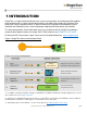
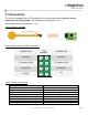
Figure 6 DAQ Connection Requirements
2.3 I
2
C Interface
The SingleTact I
2
C interface supports the standard (100 Kbits/s) clock rate in 7-bit address mode.
The SCL and SDA lines must be pulled up to the bus voltage which can be between 3V and 5V.
Please refer to the I2C specification for bus protocol implementation & pull-up value considerations.
The interface board will always respond to two I
2
C addresses: 0x04 and the address specified in
flash (register address 0). As shipped the default flash address is also 0x04.
Multiple sensor interfaces may be connected to a single I
2
C bus. The bus address of individual
sensor interfaces can be configured by writing desired address value (4 to 127) via the I
2
C interface
to register address 0 with an I2C Write Operation. Change of individual sensor I
2
C addresses is
supported by the PC and Arduino Example.
NOTE: As the interface board will always respond to address 0x04 then this address must be
considered reserved for SingleTact. Where multiple SingleTact interfaces are to be connected to the
same I
2
C bus then address 0x04 must be considered invalid and in this use case the configurable
address of all connected SingleTact nodes must be individually changed from the default value before
each SingleTact is added to the multi-node bus.
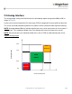
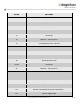
The SingleTact software architecture is based on a 192 byte register block – see Figure 7 and
Table 2 for details.
All control registers are located in first 112 bytes and get written to NVM when modified (and are
therefore persistent after a power cycle). Configuration registers on Calibrated sensors interfaces are
protected from modification.
The sensor results are available from bytes 128 to 133. As shipped, results are updated at >140Hz
(this is dependent on capacitance sensor settings).
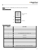
CONNECTION
No Connect
No Connect
No Connect
Ground
1
4
3
2
8
5
6
7
CONNECTION
No Connect
No Connect
Analog Out
Vcc
PIN
NUMBER