
User Manual


pg. 13
Copyright © 2017- www.SingleTact.com
Reading outside of the valid range will fail.
I
2
C slave Read operations simply return the register data values up to the number of requested bytes
(32 max) in the data packet.
NOTE: A sensor output reading below 0x0100 may indicate negative pressures, which occur when
the sensing area is under tension. This should be avoided since it can damage the internal structure
of the sensor.
NOTE: Sensor over pressure should be limited to less than 3x FSR to avoid damaging the sensor.
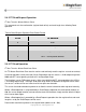
Table 5 I
2
C Master Read from Slave Data Packet Format
BYTE
FROM SENSOR
0 - 31*
Register Data Read Location-Read Location+31*
* number of bytes read can be modified by a preceding read-request command.
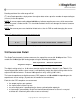
2.5 Conversion Detail
The SingleTact electronics interface measures the capacitive sensor with 16-bit precision. This is
scaled to a 10-bit digital (2V analog) output using the following calculation:
The digital scaling value is a 16-bit value stored at register locations 10 and 11 (see Table 2). For
increased precision (within a given sensor’s valid operating range) the digital scaling value can be
adjusted in 0.01 increments. A value of 100 represents unity scaling (100 x 0.01).
The internal capacitance to digital converter (CDC) operates at 140 to 4000 Hz depending on the
capacitance sensor settings (in particular the number of accumulations).
Each time the CDC completes a measurement
the output register gets updated
the frame index increases by one
an active high pulse is produced on the frame synchronization output pin
a timestamp is generated by SingleTact interface board (however as there is no crystal
oscillator this should only be used as a coarse estimate).
𝑺𝒊𝒏𝒈𝒍𝒆𝑻𝒂𝒄𝒕 𝑶𝒖𝒕𝒑𝒖𝒕 =
𝑹𝒂𝒘 𝒄𝒂𝒑𝒂𝒄𝒊𝒕𝒂𝒏𝒄𝒆 − 𝑩𝒂𝒔𝒆𝒍𝒊𝒏𝒆 𝒄𝒂𝒑𝒂𝒄𝒊𝒕𝒂𝒏𝒄𝒆
𝑫𝒊𝒈𝒊𝒕𝒂𝒍 𝒔𝒄𝒂𝒍𝒊𝒏𝒈 𝒗𝒂𝒍𝒖𝒆