
User Manual


pg. 11
Copyright © 2017- www.SingleTact.com
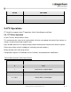
BYTE
SETTING
133
Sensor output LSB
134 - > 191
Reserved
*1 Should only be used as a coarse estimate as it is subject to drift.
2.4 I
2
C Operations
I
2
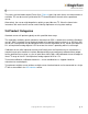
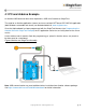
C SingleTact supports three I
2
C operations: Write, Read Request and Read.
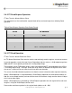
2.4.1 I
2
C Write Operation
I
2
C bus Transfer: Master Write to Slave.
This command writes values to the register block. All writes also update the internal flash memory so
settings are persistent through a power cycle.
Bytes 3 to N-1 (where N is the packet length) contain the data to be written to consecutive registers.
Data may be written to the first 128 bytes (excluding reserved locations).
Writing outside of the valid range will fail.
Configuration registers on Calibrated sensors interfaces are protected from modification.
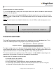
Table 3 Write Operation Data Packet Format
BYTE
TO SENSOR
0
0x02
1
Write offset in register block
2
Number of bytes to write (1 – 28)
3 -> (N-1)
Data to write (1 to 28 bytes)
N (max 31)
0xFF – end of packet delimiter